Entering beams
Beams are inserted using the "Beam" option, available in the "Bars" group of the top toolbar, under the "Geometry" tab (in the "Structure" tab).

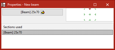
Defining the properties of the beam
In the window that appears when clicking on the "Properties – New beam" option, the diagram on the right allows adjustment of the section position relative to the input line by clicking on the centre, edge, or corner markers.
If beams have already been inserted in the model, the program allows selecting one of the "Sections used" from the table at the bottom.
If this is the first beam being inserted, or if a new section is to be "Described", click the central button.
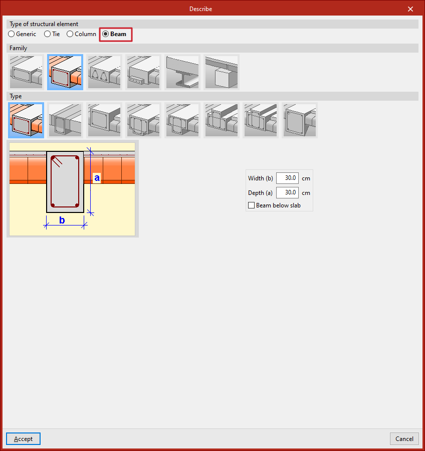
In the pop-up window, the programme allows you to specify the "Family" and "Type" of beam to be inserted, along with its dimensions and characteristics.
The available beam families are described below.
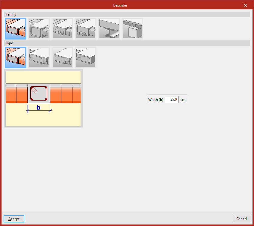
Flat beams
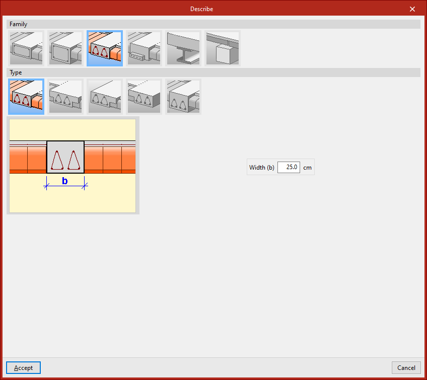
"Flat beams" are those with the same depth as the slab. The available types of flat beams include:
- Flat rectangular beam
- Flat 'T' beam
- Flat beam with right flange
- Flat beam with left flange
Flat beams will automatically adopt the depth of the panel in which they are located. Therefore, the program only requires the definition of their "Width (b)". If the beam is located between two panels of different depths, it will take the greater of the two. If positioned between two panels at different levels, the beam depth will increase to cover the height difference.
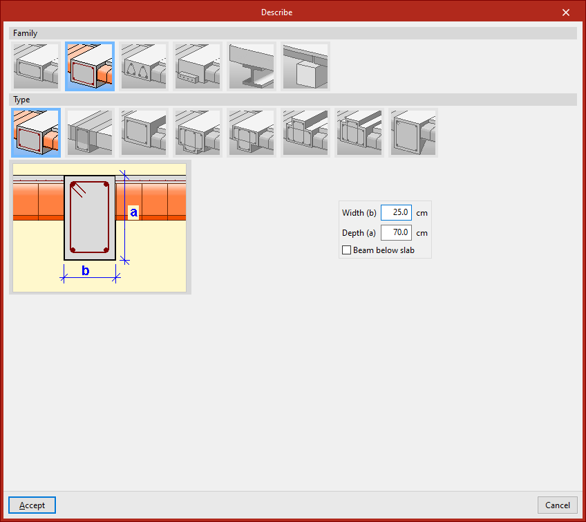
Dropped beams
"Dropped beams" have a depth different from the slab. Available types of dropped beams include the following:
- Dropped rectangular beam
You must specify the "Width (b)" and "Depth (a)". If the "Beam below slab" checkbox is ticked, the top face of the beam aligns with the bottom face of the slab. If left unticked, it aligns with the top face of the slab.
- Dropped rectangular beam with collaborating head
In this case, you must also specify the lengths of the "Left flange (i)" and "Right flange (d)" of the concrete section that works together with the beam.
- Inverted rectangular beam
This type aligns its bottom face with the bottom face of the slab and places its depth above.
- Dropped 'T' beam
- Dropped 'T' beam with embedded flange
- Inverted 'T' beam with embedded flange
- Inverted 'T' beam
The T-beam options, whether dropped, inverted, or with an embedded flange, allow the definition of a reinforced section in this shape, using the options "Width (b)", "Depth (a)", "Left flange (i)", "Right flange (d)", and "Flange depth (s)" where necessary.
- Dropped rectangular beam with variable section
This option allows defining a beam with a variable section using a given "Width (b)" and an "Initial depth (a)" which may differ from the "Final depth (c)".
Lattice beams
"Lattice beams" are a type of beam with prefabricated reinforcement.
Their characteristics must be provided by the manufacturer and defined within the general project data (under the "Project" tab, options "General data", "Beams", "Options", "Reinforcement arrangement", "Lattice beams").
The available options include:
- Flat rectangular lattice beam
- Flat 'T' lattice beam
- Flat rectangular lattice beam with right flange
- Flat rectangular lattice beam with left flange
- Dropped rectangular lattice beam
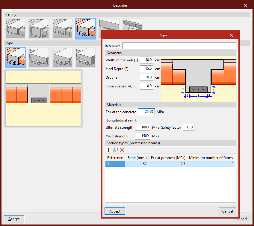
Prestressed beams
"Prestressed beams" have a prefabricated base and form their complete section during concreting together with the slab and the negative reinforcement placed in situ.
To define them, edit the prestressed beam library by clicking the corresponding button. Select "New", then define the "Reference", "Geometry", and the characteristics of the "Materials", both for the concrete and the longitudinal reinforcement, and add the available "Section types".
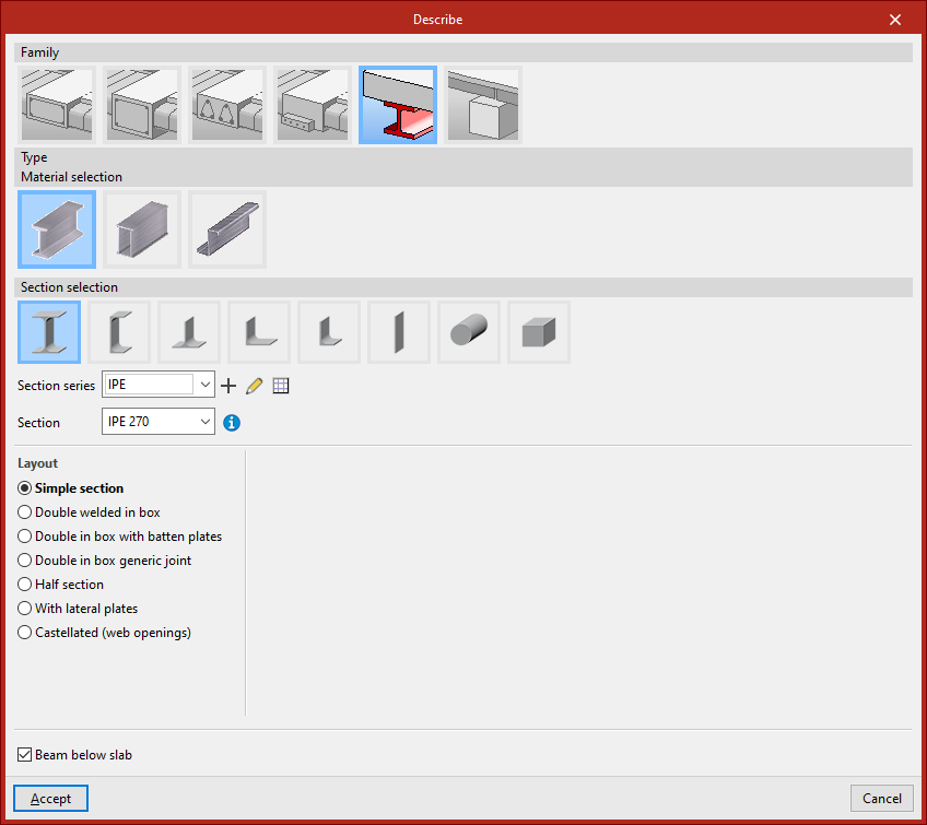
Steel beams
Within the "Steel beams" family, the following beams are available: "Rolled steel section", "Built-up section with rolled steel plates", and "Cold-formed steel section".
After selecting the material, you can configure the "Section selection" panel, which allows you to choose from a variety of available sections.
You can indicate that it is a "Beam below slab" by ticking the checkbox at the bottom.
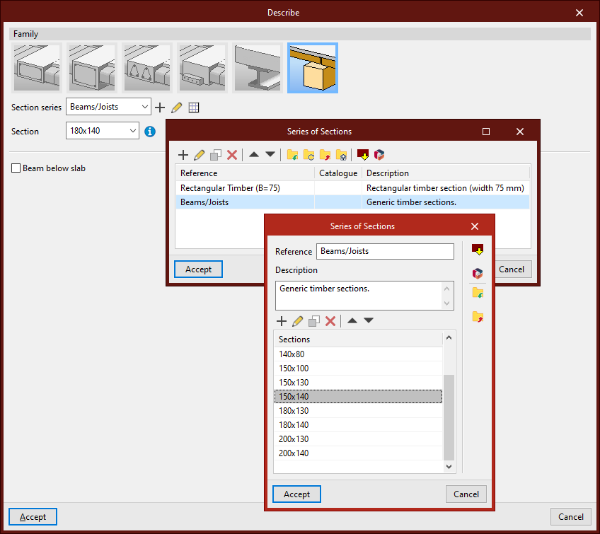
Timber beams
The "Timber beams" family allows for the use of beams made of this material.
The section geometry of timber beams is defined using the libraries located next to the "Section series" and "Section" dropdowns.
The "Beam below slab" checkbox allows you to indicate this situation.
Inserting the beam in the model
A beam is defined by its start and end nodes, so two points must be selected using the left mouse button. By clicking again with the left button, you can continue inserting more beams.
To finish, right-click. At that moment, the program will create a continuous beam from all inserted elements, if possible.
A beam cannot be completely vertical. Moreover, the angle between its local XZ plane and the vertical plane it lies in must be zero. That is, no rotation about the longitudinal axis of the beam can be inserted.
A beam does not need to belong to a level, but if a level is defined, the beam will be assigned to the nearest lower level.
Inserting beams using the "Bar" option
Beams can also be inserted using the "Bar" option from the "Bars" group. Then, click the central edit button and in the "Type of structural element" section, select "Beam".
After clicking "Accept", the points that define the beam geometry are inserted as described above.