Entering columns
Columns are entered using the "Column" option, available in the "Bars" group on the top toolbar, within the "Geometry" tab (in the "Structure" tab).

To proceed, at least two levels must have been previously defined in the project. Levels can be viewed, created, or deleted from the "Drawings" menu at the top of the interface, also in the "Geometry" tab, by selecting the "Levels" option.
Defining column properties
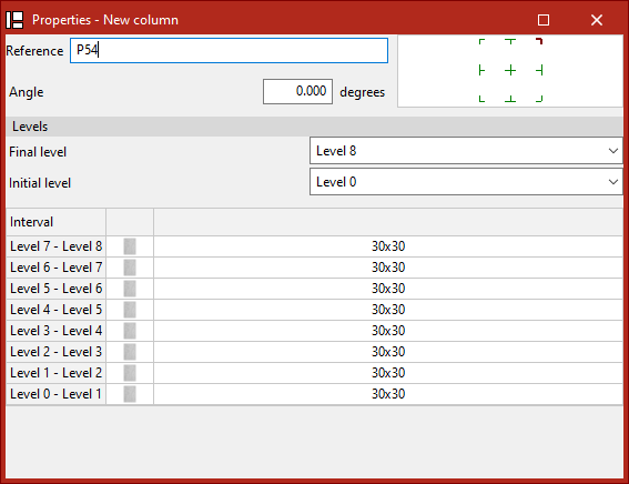
The "Column" option allows you to introduce a new column. When this option is selected, a pop-up window ("Properties – New column") appears, where its characteristics are defined.
Here, the "Reference" of the column and its "Rotation angle" in plan are entered. In the diagram on the right, the positioning of the section relative to the insertion line can be adjusted by clicking the centre, edge, or corner markers.
Next, under the "Levels" section, select the "Top level" and "Bottom level" of the column from the dropdown menus.
In the lower table, the section of the column is specified for each of the "Intervals" defined between levels.
To do this, click in the cells of the right-hand column. A window will open where the "Type of section" can be modified.By holding down the Ctrl key, you can select multiple intervals at once by clicking on them one by one. If you press the Shift key, you can select a range of intervals by clicking the final and initial interval. This way, the same section can be applied to all selected intervals.
Defining the column section type
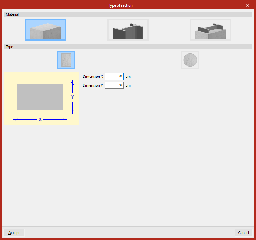
Under the "Material" section, choose whether the column is "Reinforced concrete", "Steel", or "Composite section".
Reinforced concrete columns
For "Reinforced concrete" columns, the next step is to specify the "Type".
Rectangular concrete columns
If the column is "Rectangular", enter its "X dimension" and "Y dimension", following the directions of the local coordinate axes of the element.
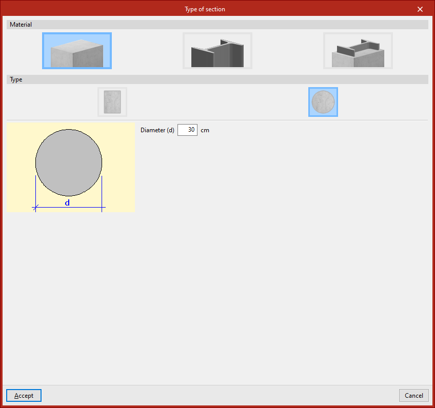
Circular concrete columns
If the column is "Circular", its "Diameter" is defined.
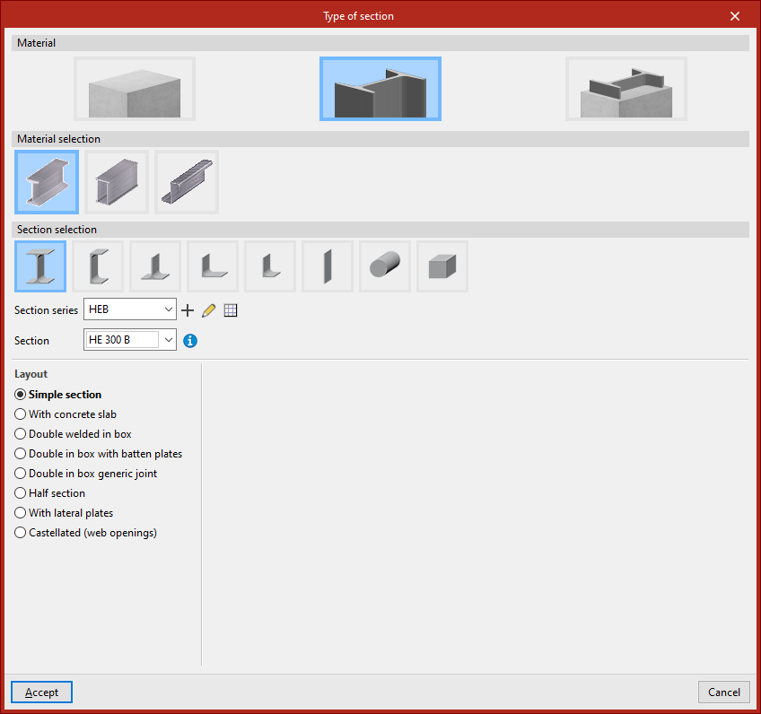
Steel columns
For "Steel" columns, you must perform both the "Material selection" and the "Section series" from the options available in the program. These are very similar to those used when inserting generic rolled or cold-formed steel bars.
Composite section columns
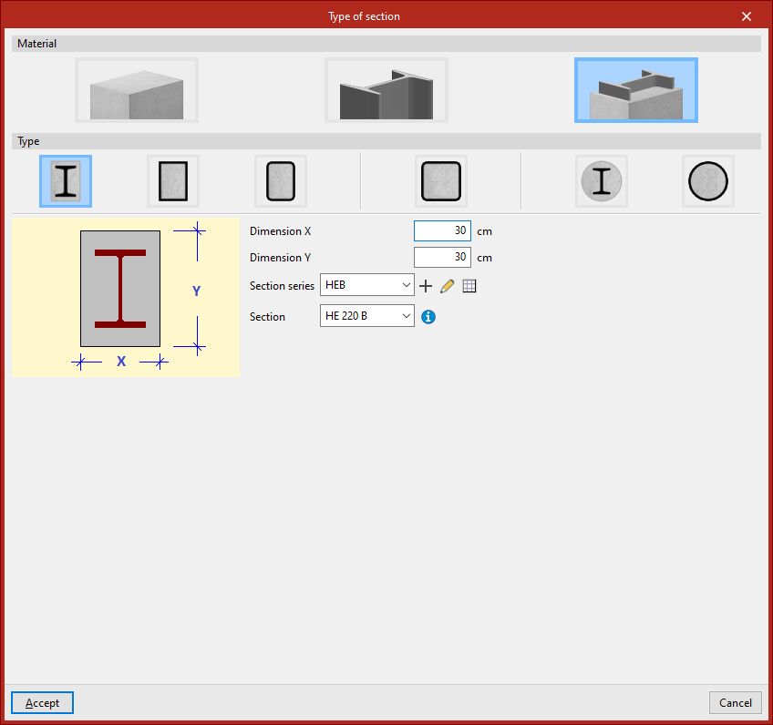
For "Composite section" columns, first select the "Type".
Concrete columns with embedded sections
For a "Rectangular column with encased section", enter the total section’s "Dimension X" and "Dimension Y", then define the "Section series" and select the "Section" of the embedded element.
Similarly, for a "Circular column with encased section", specify the "Diameter", and again select the appropriate "Section series" and "Section", as in the previous case.
Concrete-filled steel box and tube sections
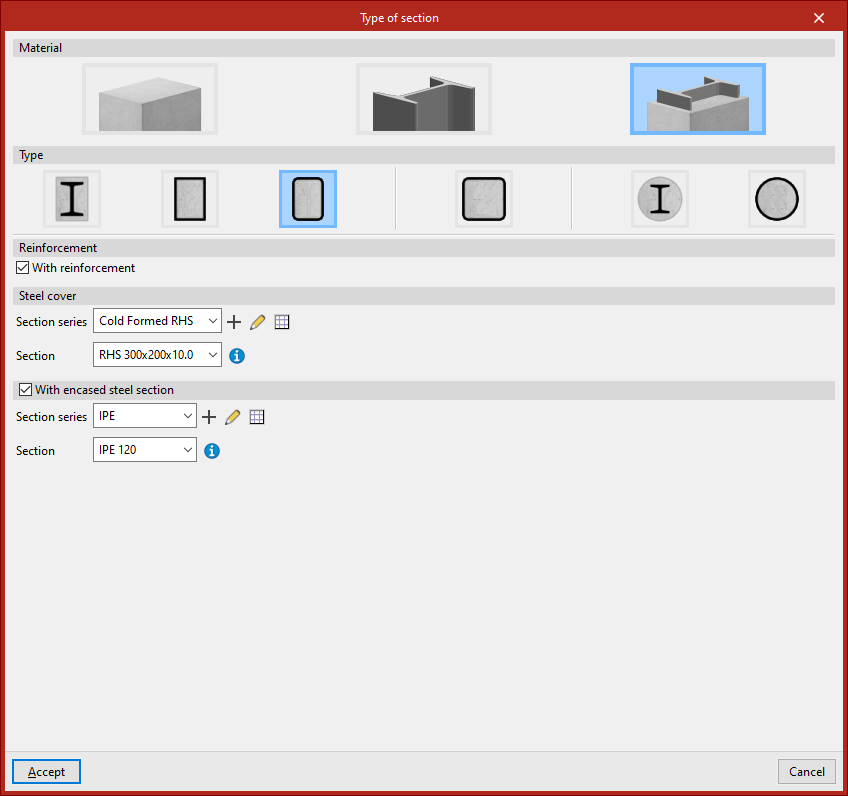
It is also possible to insert a "Rolled steel plate rectangular box section, filled with concrete".
In this case, under the "Reinforcement" section, tick the box "With reinforcement" if the column includes reinforcement. Then, under "Steel cover", define the "Section series" and select the "Section" that forms the outer tube or box.
You can also tick the "With encased steel section" box. Again, indicate the "Section series" and select the "Section" of the element embedded in the concrete.
Other available options include introducing a "Rectangular hollow section", "Square hollow section", or "Cold-formed circular hollow section, filled with concrete", all of which are used in a similar manner.Once the section type has been defined, click "Accept". Then, repeat the process for the remaining intervals.
Inserting the column in the model
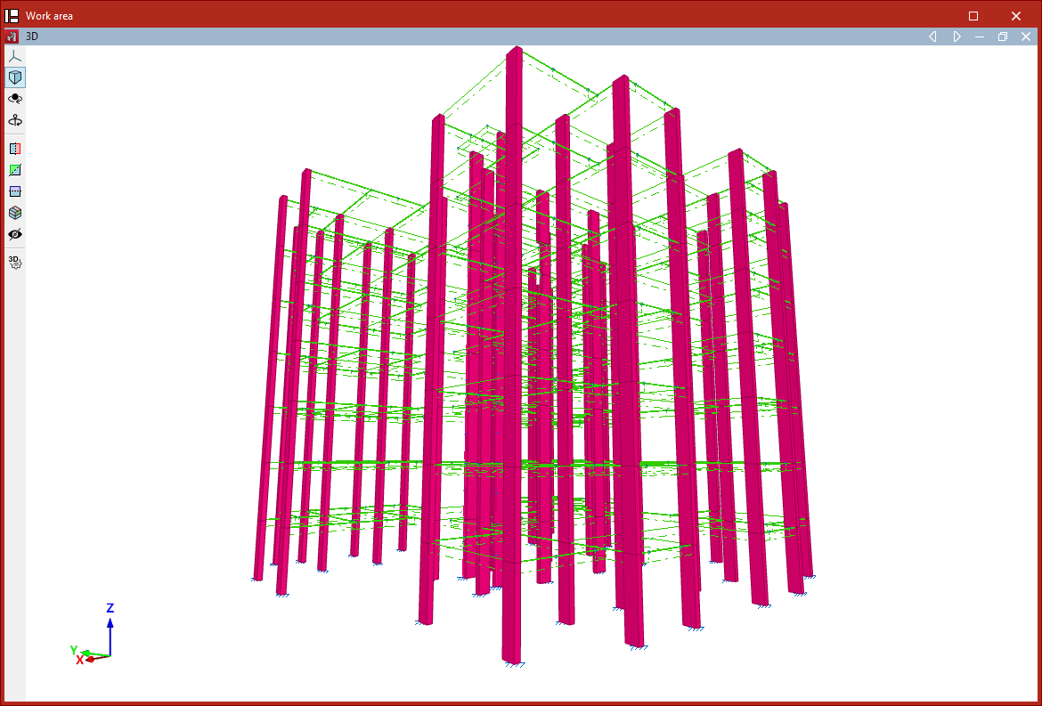
Finally, select a point with the left mouse button to place the column in the model.
The program will position the column vertically at the selected point, adjusting the height of the elements so they reach the specified levels.
An element is created between each pair of levels along the height of the column.
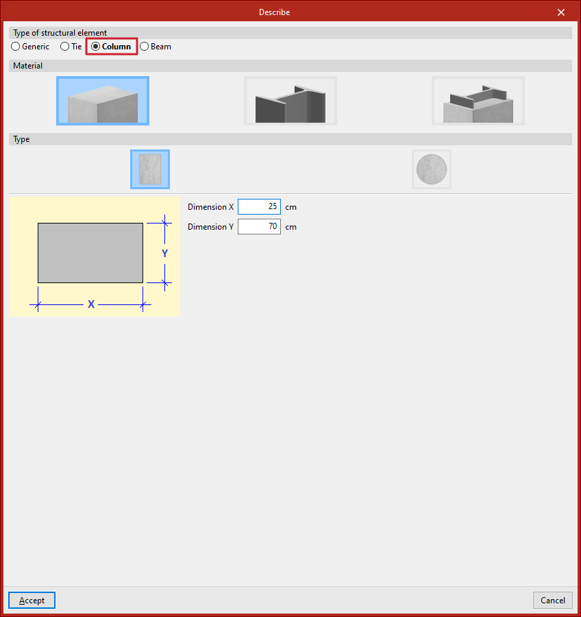
Inserting columns via the "Bar" option
You can also insert a column using the "Bar" option from the "Bars" group. Then, click the central edit button and, under the "Type of structural element" section, select "Column".
In this case, after clicking "Accept", when inserting the points that define the start and end nodes in the model, ensure that the geometry of the element is completely vertical.