Entering shells
Shells are entered using the following option, available in the "Shells" group of the top toolbar, under the "Geometry" tab (in the "Structure" section).

New
The "New" option allows you to insert a new shell into the model.
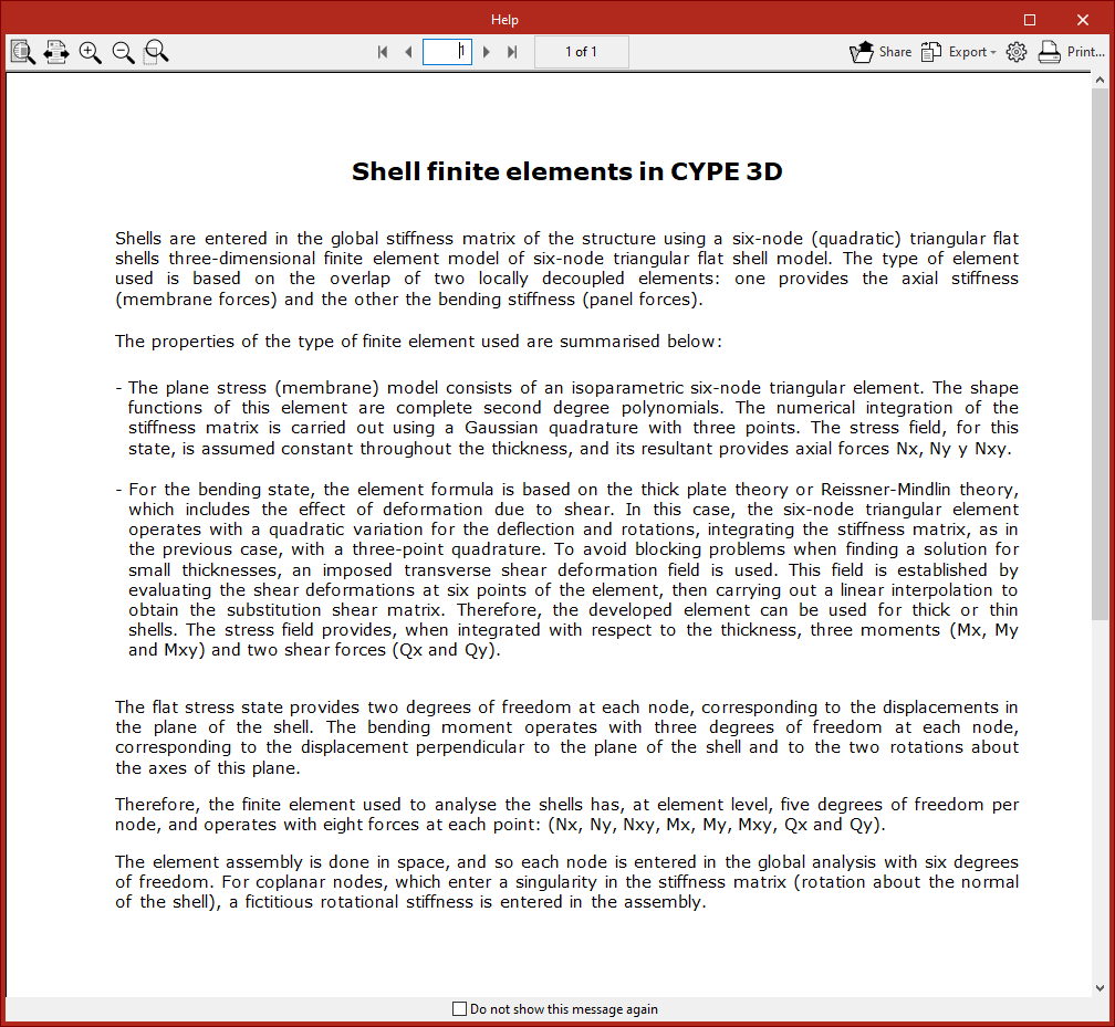
When you click this option, a message first appears explaining how the program treats finite element shells and their characteristics. You can check "Do not show this message again" if desired.
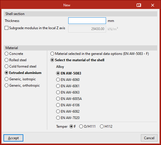
Then, the "New" window opens, allowing you to define the shell's characteristics.
Defining the shell section and material
At the top of the "New" window, the "Shell Section" data is shown, including its "Thickness" in the selected measurement units.
You can activate and enter a "Subgrade modulus in the local Z axis". This setting lets the program consider the elastic support of the shell along the axis perpendicular to its plane. This is useful for simulating scenarios like shells resting on soil.
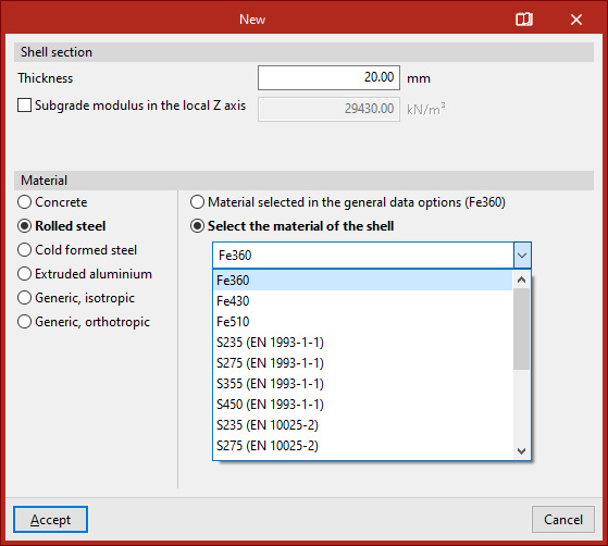
Next, the "Material" of the shell is defined. Available options include:
- Concrete
- Rolled steel
- Cold-formed steel
- Extruded aluminum
- Generic, isotropic
- Generic, orthotropic
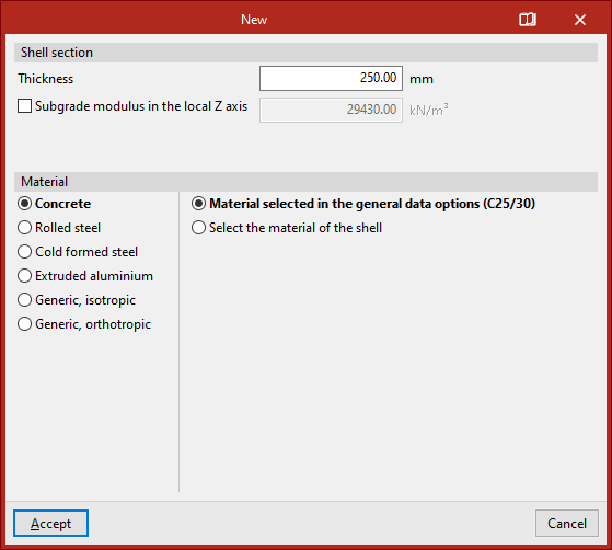
If one of the first materials is chosen, an option appears on the right to either "Material selected in the general data options" or "Select the material of the shell" directly from a dropdown list.
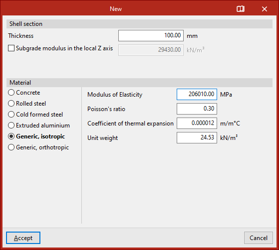
Generic isotropic material shells
If "Generic, isotropic" is selected, you must directly specify the "Modulus of Elasticity", "Poisson’s ratio", "Coefficient of thermal expansion" and the "Unit weight".
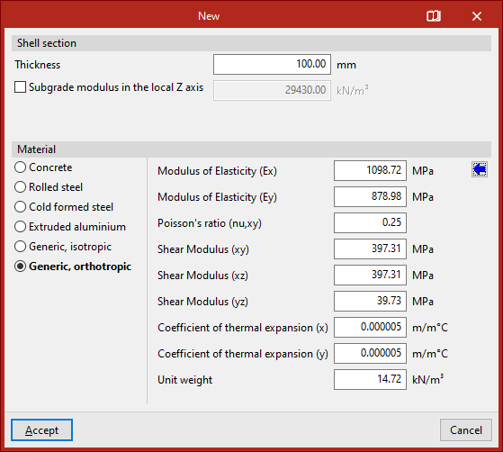
Generic orthotropic material shells
If "Generic, orthotropic" is selected, you must specify the "Elastic modulus" in both X and Y directions (Ex, Ey), "Poisson’s ratio (nu, xy)", the "Shear modulus" in the XY, XZ, and YZ planes, the "Thermal expansion coefficient" in X and Y and the "Unit weight".
This option is useful for analysing structures made of cross-laminated timber (CLT) panels.
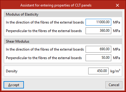
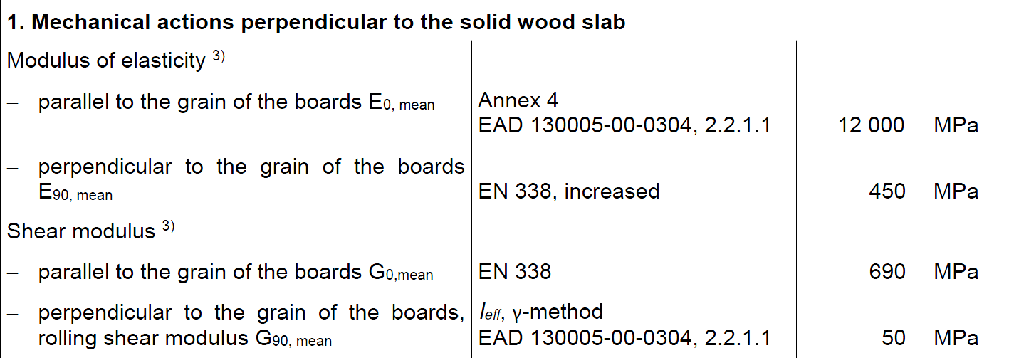
To assist the user, a button on the right provides access to a "Assistant for entering properties of CLT panels".
This tool helps input data as specified by a CLT panel manufacturer in their European Technical Assessment (ETA) document.
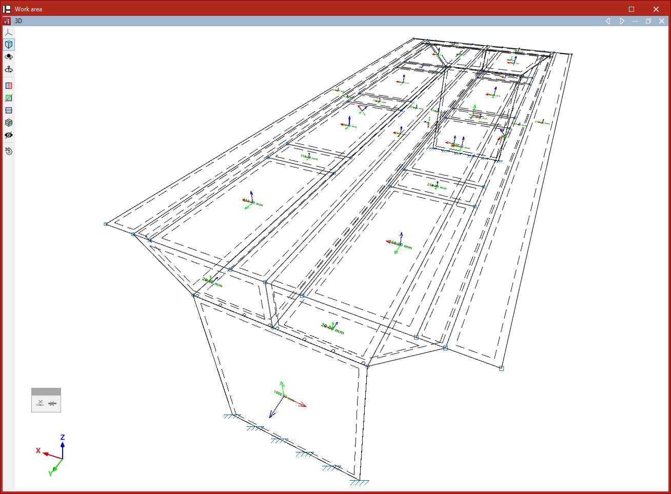
Inserting the shell into the model
After clicking "Accept" in the "New" window, you define the polyline points that outline the shell in the work area using the left mouse button.
As with inserting bars, you can use object snaps and template snaps, among other options.
During the input process, you can "Erase the last entered point", or "Erase all entered points", using the controls provided in the dedicated input box.
Once all perimeter points are selected, right-click to finish.
After inserting the first shell, you can continue drawing more shells in the model, or right-click to return to the definition panel. When clicking "Cancel" or closing the panel, you exit the option.
The shell will be connected to the rest of the structure if its edges are in contact with its edges, or if there are nodes or bars within its geometry.