External fixity definition for shells
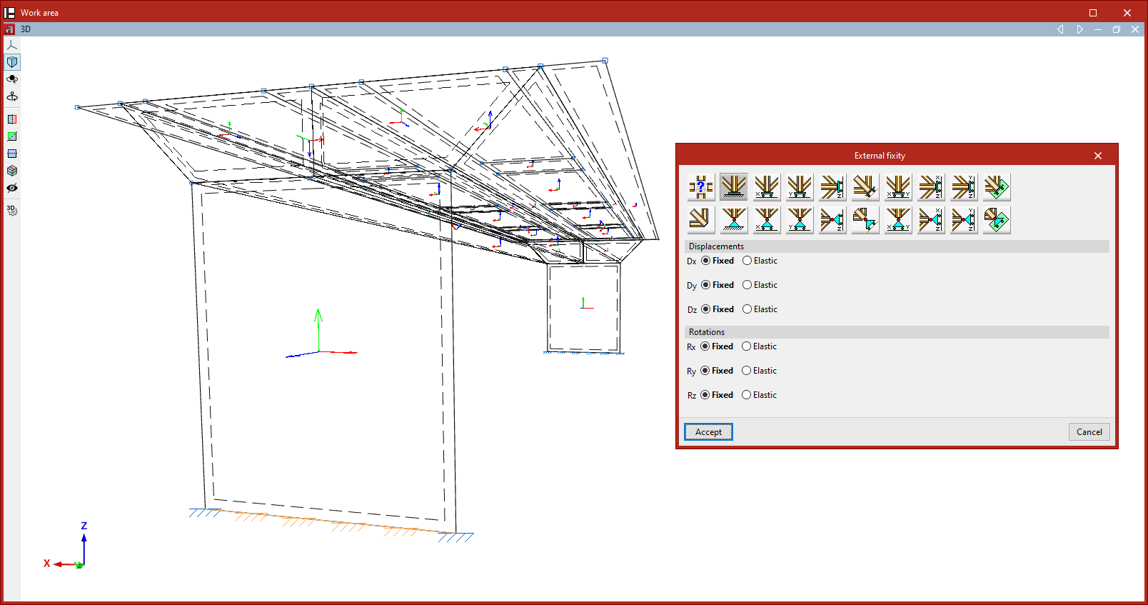
The definition of external fixities on the edges of shells is carried out using the following option, available in the "Shells" group on the top toolbar, within the "Properties" tab (under the "Structure" section):

External fixity
To edit the external fixities of a group of edges, use the "External fixity" option.
After selecting the option, choose the edges to be edited using the left mouse button or by drawing a selection box, then right-click.
The program will open a window where you can choose the type of external fixity, which will be applied once you click "Accept".
External fixities define the global constraints on the selected edges. They restrict the displacement or rotation of the edge nodes and correspond to supports on the ground or on other external elements in the model.
The defined external fixity affects the internal nodes of the edge created by the discretisation of the shells, as well as the end nodes, if no external fixity has already been defined for them.
If an edge node is shared by edges with different external fixity conditions, none will be applied, and the node will remain unconstrained. The program displays a warning for such conflicting nodes in the "Analysis" tab using the "Show/Hide issues" option.
Free
By default, the edges of a newly introduced shell are defined as "Free", i.e., with no external fixity.
The remaining options allow you to define external fixity on the edge:
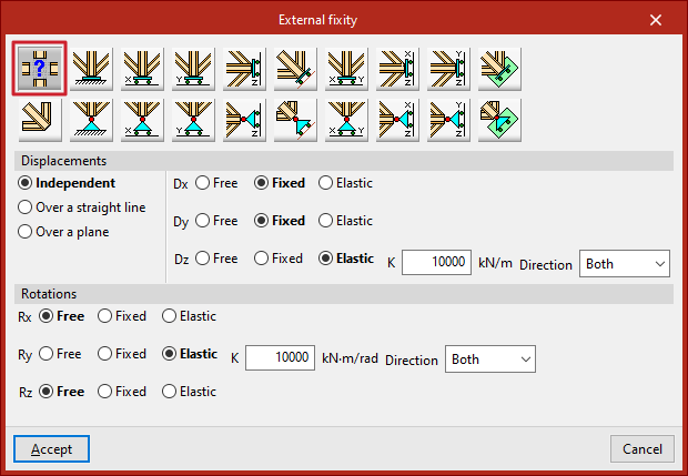
Generic
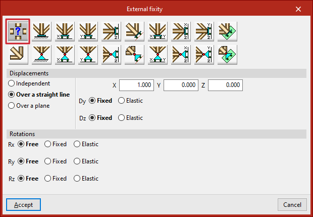
The "Generic" option allows you to manually define constraints on displacements and rotations in all three spatial directions.
Displacements
The displacements can be "Independent", "Along a line" or "On a plane".
For those defined as "Independent", the behaviour of the displacements along the three axes, Dx, Dy, and Dz, is specified:
- Free – the displacement in that direction is unconstrained.
- Fixed – the displacement is constrained to a fixed value (default is zero unless modified by the "Prescribed displacements" option under the "Load" tab).
- Elastic – an elastic support is applied in that direction. You must specify the stiffness constant of the support in the indicated units and its Direction ("Both", "Negative", or "Positive").
For displacements defined as "Along a line", the edge nodes may only move in the direction of a vector defined by its X, Y, and Z components entered on the right. In the perpendicular directions, the support can be specified as "Fixed" or "Elastic".
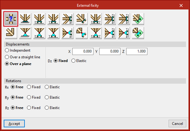
For displacements defined as "On a plane", the edge nodes may move within a plane perpendicular to a vector defined by the entered X, Y, and Z components. In the direction normal to the plane, the support can be either "Fixed" or "Elastic".
Rotations
For Gx, Gy, and Gz "Rotations", the following can be defined:
- Free – the rotation is unconstrained in that direction.
- Fixed – the rotation is constrained to zero.
- Elastic – an elastic rotational support is applied. You must provide the stiffness constant and specify the Direction ("Both", "Negative", or "Positive").
The remaining options in the "External fixity" panel correspond to predefined fixities that simplify data input and speed up the process:
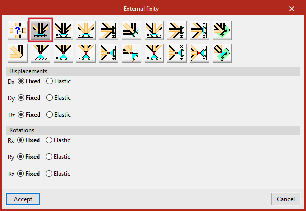
Fixity
The "Fixity" option fully restrains displacements (Dx, Dy, Dz) and rotations (Gx, Gy, Gz) in all three directions at the nodes of the selected edge.
Each displacement or rotation must be defined as either "Fixed" or "Elastic".
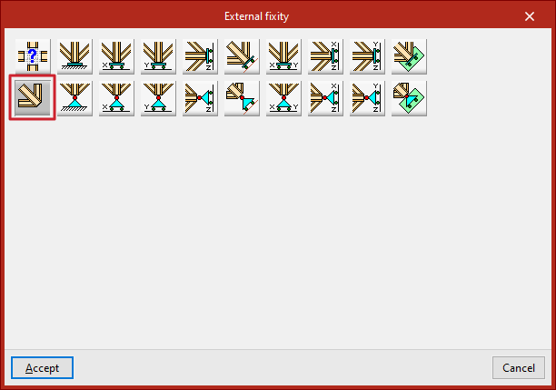
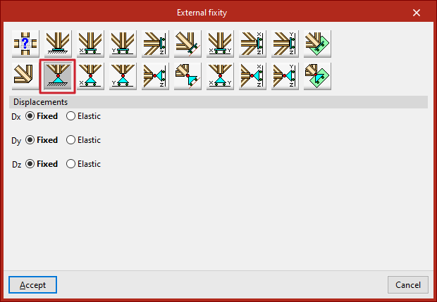
Pinned
The "Pinned" option restrains only the displacements (Dx, Dy, Dz) in all three directions at the nodes of the selected edge, while allowing rotations.
Each restrained displacement must be defined as either "Fixed" or "Elastic".
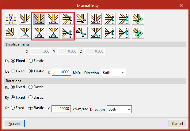
Free displacements along a line in the X, Y, or Z direction
These options allow free displacements along a line in the global X, Y, or Z directions.
The first row defines fixed supports with free displacement and also restrains rotations:
- Free displacement along the X direction
- Free displacement along the Y direction
- Free displacement along the Z direction
The second row defines pinned supports with free displacement and leaves rotations unconstrained:
- Free displacement along the X direction with unconstrained rotations
- Free displacement along the Y direction with unconstrained rotations
- Free displacement along the Z direction with unconstrained rotations
In all cases, the components of the line’s direction vector are pre-filled in greyed-out numeric fields. The user must specify whether displacement or rotation in each direction is "Fixed" or "Elastic".
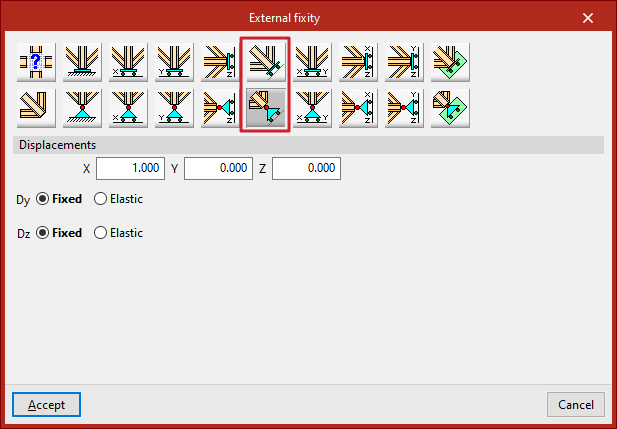
Free displacements along an arbitrary line
These options allow free displacement along an arbitrary line, with or without constrained rotations:
- Free displacement along an arbitrary line
- Free displacement along an arbitrary line with unconstrained rotations
In this case, the user enters the components of the direction vector for the line, and specifies for each shown direction whether the displacement or rotation is "Fixed" or "Elastic".
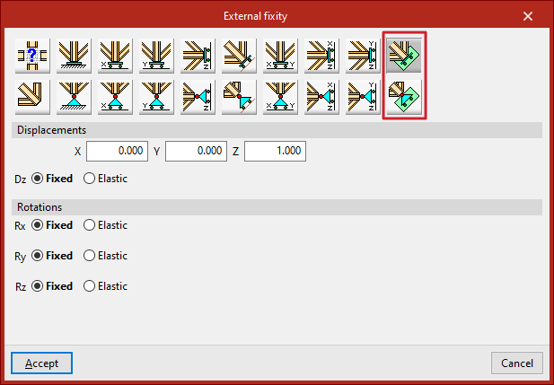
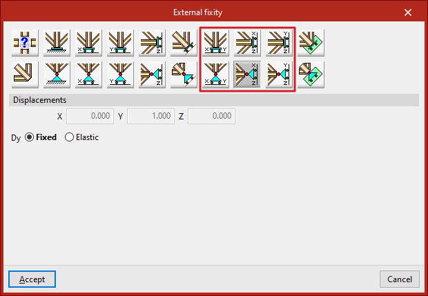
Free displacements on a plane parallel to the XY, XZ, or YZ axes
LThese options define free displacements on a plane parallel to one of the global axes (XY, XZ, or YZ).
The first row defines fixed supports with free displacement and restrained rotations:
- Free displacement on a plane parallel to the XY plane
- Free displacement on a plane parallel to the XZ plane
- Free displacement on a plane parallel to the YZ plane
The second row defines pinned supports with free displacement and unconstrained rotations:
- Free displacement on a plane parallel to the XY plane with unconstrained rotations
- Free displacement on a plane parallel to the XZ plane with unconstrained rotations
- Free displacement on a plane parallel to the YZ plane with unconstrained rotations
In all these cases, the components of the plane’s normal vector are pre-filled in greyed-out numeric fields. The user simply indicates whether displacement or rotation in each shown direction is "Fixed" or "Elastic".
Free displacements on an arbitrary plane
Finally, it is possible to define free displacement on an arbitrary plane, either with constrained or unconstrained rotations:
- Free displacement on an arbitrary plane
- Free displacement on an arbitrary plane with unconstrained rotations
You must enter the components of the plane’s normal vector and specify whether displacement or rotation in each shown direction is "Fixed" or "Elastic".