
Check forces
The force values after the analysis of the structure are checked with the following option, available in the "Stress / Strain" group of the upper toolbar, in the "Analysis" tab (in the "Structure" tab).

Forces
The "Forces" option can be used to draw on screen the forces, deflection, strain and tension graphs of both the bars and the integration strips of the sheets.
Force selection
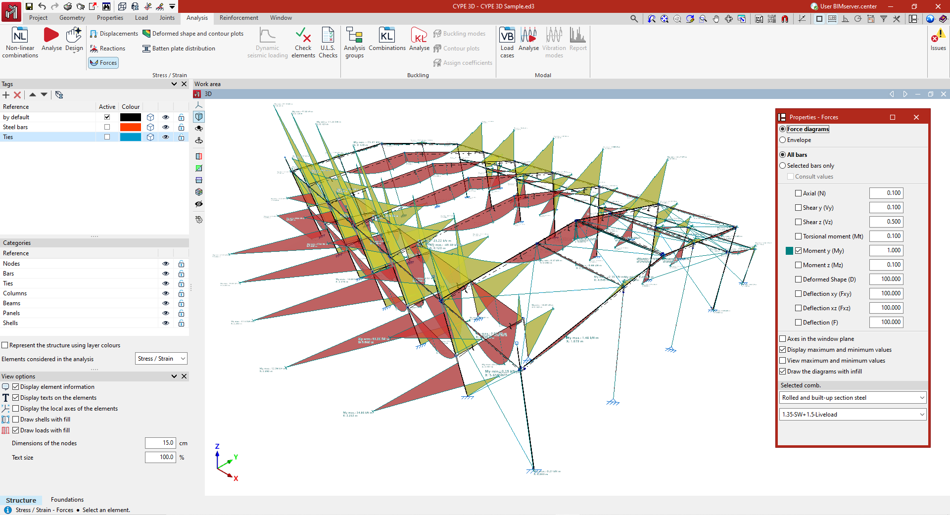
In the "Properties - Forces" dialogue box that appears, the following options can be configured.
- If "Laws" is selected, the loadcase or combination of loadcases to be checked must be indicated in the "Selected combination" section at the bottom of the window. To do this, the program provides a choice between different groups of combinations in the drop-down menus.
- By selecting "Envelopes", the program draws the maximum and minimum values of the force envelope of all the combinations used in the analysis.
The bars to be checked are then selected.
- If "All bars" is checked, the selected force graphs will be drawn for all bars in the structure.
- If "Only selected bars" is checked, each bar must be clicked on for the force graphs to be drawn.
- By activating the "Check values" checkbox, the mouse cursor can be moved along the bars to display an information box with the values calculated at the indicated point.
Among the magnitudes that can be checked by activating the boxes in the central part of the dialogue box are the following:
- the "Axil", the shear and bending moment in the two directions ("Shear y", "Shear x", "Moment y" and "Moment z"), the "Torsional moment", the "Deflection xy" and "Deflection xz", which correspond to the two planes of the profile, and the total combined "Deflection";
- with the "Laws" and "All bars" options selected, it is also possible to display the "Deformed shape" of the structure;
- and if the "Envelopes" display is activated, in addition to the stresses and deflection, the program allows users to consult information on the stress-strain ratio. This graph can examine which regions of the bars are compliant or non-compliant.
Each of the graphs is drawn in a different colour. This makes it possible to distinguish the graphs on the screen when several graphs are activated at the same time.
In addition, to the right of each of the magnitudes, the scale factor can be modified to change the size of the representation of the graphs in the viewer.
Other configuration options
Below are the following options for configuring the display of the force laws:
- The "Axes in the window plane" option displays the force graphs in a coordinate system with the axes constructed on the window plane. This can be useful to make the plots visible in some views.
- The "Draw maximum and minimum values" option adds on each graph the information of the maximum and minimum values they reach, as well as the position at which they occur.
- Finally, if only one graph is activated, "View maximum and minimum values" can be selected. In this case, the mouse cursor must be moved over the bars so that the program displays the maximum and minimum values in each one of them.
- It is also possible to configure the display of the force diagrams so that they are shown filled with colour by activating the "Draw the diagrams with infill" checkbox.
- If the "Display stress using contour lines" option is deactivated when viewing the stress/strain graph, the bar sections in which the stress complies with the normative limitations are shown in green, and those that do not comply are shown in red. If "Display stress using contour lines" is activated, the values of the stress graph are detailed using a range of colours, showing a value between zero and the maximum stress value. The legend at the bottom of the display allows these colours to be interpreted.