
Defining limit states (combinations)
The load combinations for each limit state are configured in the "Project" tab (under the "Structure" section) by selecting the "General data" option in the "Project" group on the top toolbar.

"Limit states (combinations)" option
At the bottom of the window, in the "Loads" section, click on "Limit states (combinations)".
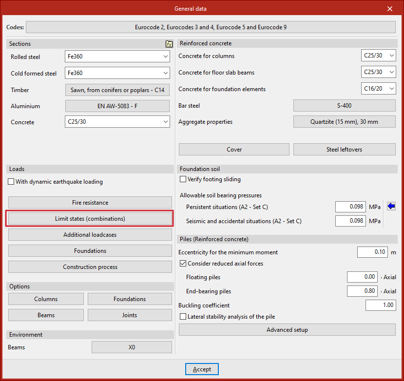
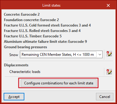
This opens the "Limit states" window, where the data required to check the structural elements against the ultimate limit states of the various materials is specified. In addition, the combinations for "Ground bearing pressures" and "Displacements" are defined.
By default, the software automatically generates combinations for the limit states of each material in accordance with the requirements of the selected standard.
You can view the generated combinations by clicking on the buttons on the right-hand side.
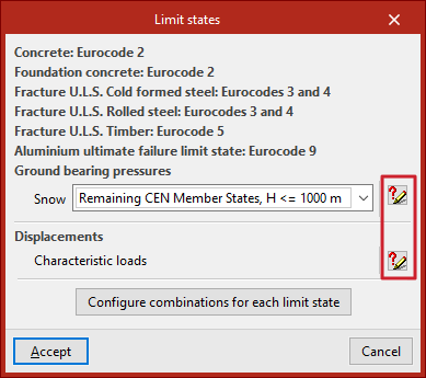
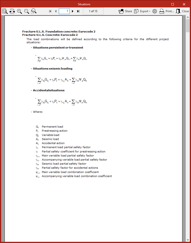
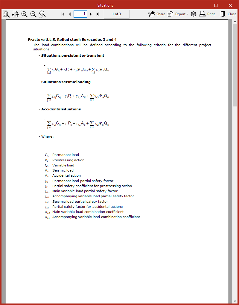
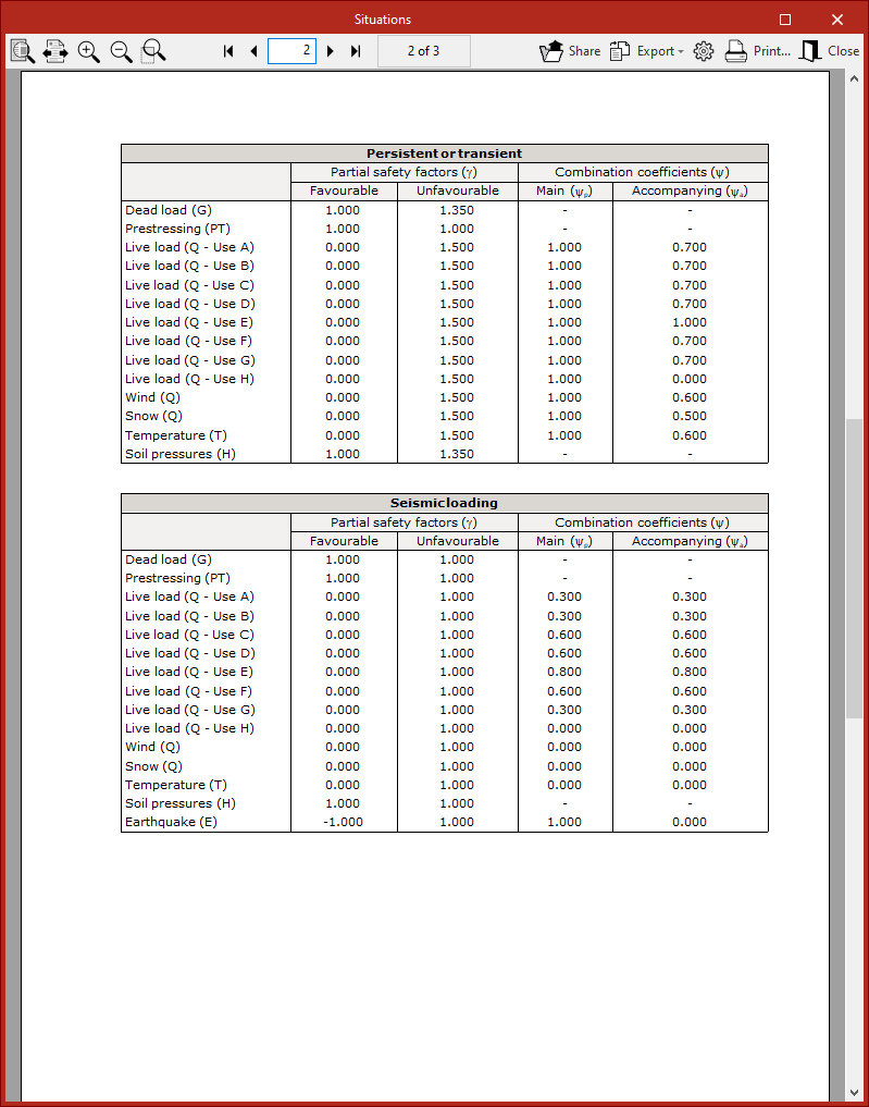
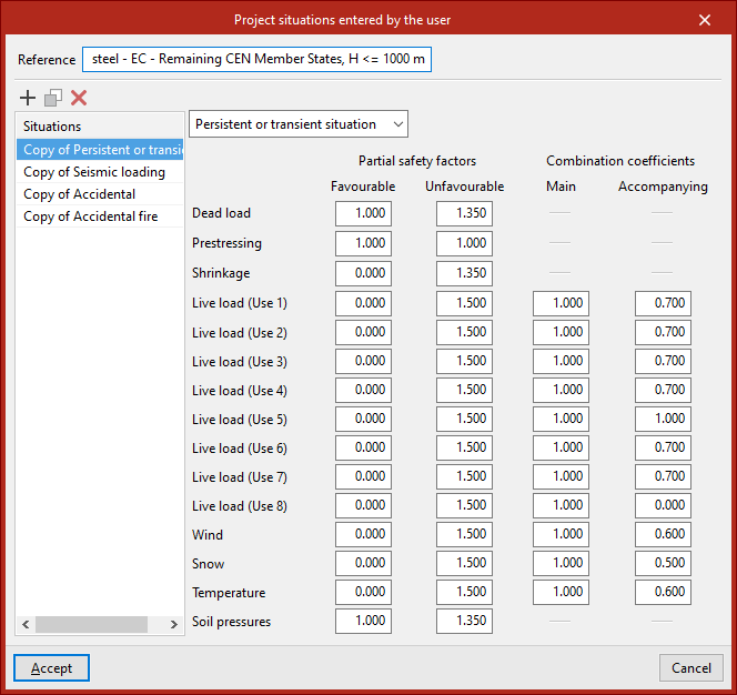
This displays a report of the project "Situations" defined for each limit state. These include "Persistent or transient scenarios", "Seismic scenarios" and "Accidental scenarios".
In each of these situations, the mathematical expression that relates the operations and the coefficients that multiply or divide them appears.
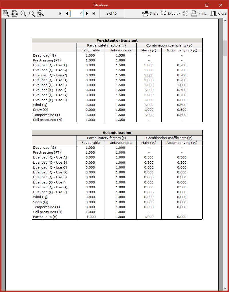
The following are then shown in a series of tables:
- the "Partial safety factors" (γ) or adjustment factors for each load, depending on whether they are "Favourable" or "Unfavourable";
- and alongside them, the "Combination coefficients" (ψ), both the "Main" and the "Secondary" coefficients.
Configuring combinations for each limit state
To enter and modify the load combinations manually, click the "Configure combinations for each limit state" button at the bottom of the "Limit states" window.
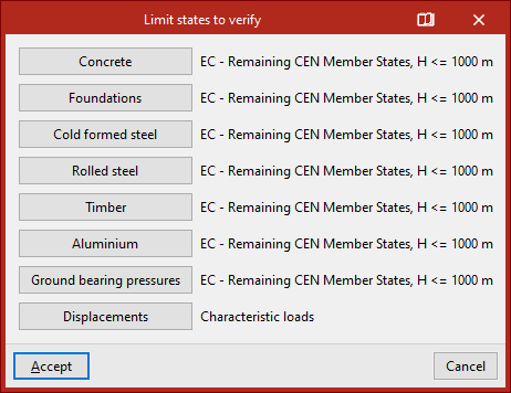
This opens another window where specific combination factors can be set for each of the "Limit states to verify" associated with each material:
- Concrete,
- Concrete for foundations,
- Formed steel,
- Rolled steel,
- Timber,
- and aluminium.
- It is also possible to modify the combinations for "Ground bearing pressures" and "Displacements".
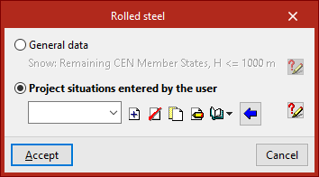
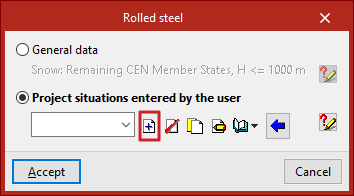
In the window that appears when you click one of these options (for example, "Rolled steel"), if the first option remains selected, the program uses the default combination settings specified in the standard selected under "General data".
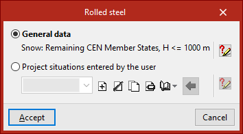
Once again, by clicking on the button on the right, you can view the specific report of project loadcases defined for the selected limit state.
Conversely, if you wish to make changes, you must tick the box marked "User-defined project scenarios".
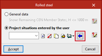
Below is a drop-down menu showing the available project scenarios. The buttons on the right allow you to "Create", "Delete", "Copy" and "Edit" project scenarios, as well as "Import", "Export" and "Edit" information in a library.
Creating project scenarios based on those defined in the standard
The easiest way to add and edit project scenarios is to "Create based on the code situations". To do this, click on the blue arrow button.
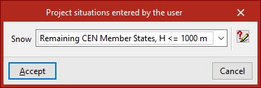
Next, click "Accept" after selecting the specific option "Snow", in accordance with the selected regulations.
In this way, the program automatically generates all the information relating to project situations, whilst also allowing it to be edited.
At the top, you will see the "Reference", which can be edited. The table on the left shows all the project "Situations". Here, you can "Add", "Copy" or "Delete" stages.
Each of these is already defined as "Persistent or temporary situation", "Seismic", "Accidental" or "Accidental fire" via the drop-down menu.
Furthermore, the various cells show all the values for the different "Partial safety factors", whether the load is "Favourable" or "Unfavourable", as well as the "Combination factors"—both the "Main" and the "Secondary" factors—as specified in the selected standards.
Users are free to modify each of these values to adjust the analysis to their requirements, and then click "Accept".
Creating project situations from scratch
Project situations can also be created from scratch. To do this, in the previous window, click the "Create" button to the right of the drop-down menu.
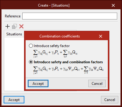
First, enter the "Reference". Then, in the list below, add the various "Situations" by clicking "Add".
When creating scenarios, you can choose whether to "Enter safety factor" only or "Enter safety and combination factors".
After clicking "Accept", the program may prompt you to "Define new use categories" or select "Predefined use categories".
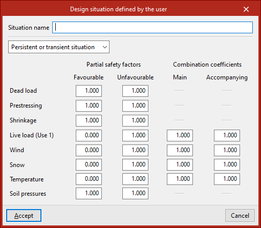
After clicking "Accept", the project situation is defined. To do this, enter the "Situation name", select the situation type from the drop-down menu, and enter all the coefficients in the relevant cells.
This process should be repeated for each project situation you wish to add; these will be added to the list.
Finally, click "Accept". This means that the manually defined project situations will also appear in the drop-down menu in the previous window.
Finally, to apply the selected settings and confirm the changes, click "Accept" again until you return to the program's main interface.