Generating geometry by importing DXF or DWG files
In CYPE 3D, it is possible to automatically generate the structure’s geometry by importing data from a DXF or DWG file. To do this, use the “DXF or DWG” option, which is available in the “Import” section of the top toolbar, within the “Geometry” tab (under the “Structure” tab).

| Note: |
|---|
| This option allows for the automatic generation of beams, panels and/or sheets as native elements in CYPE 3D and differs from the template import function available via the "Edit templates" option, located in the toolbar at the top right of the interface. In the latter case, the elements of the imported .dxf or .dwg file are used solely as a reference or aid in the drawing process, via a snapping system. |
Select the DXF or DWG file
When you click on the "DXF or DWG" option, a dialogue box opens, allowing you to browse for a file in either of these two formats. The drawing units in the selected file must be set to metres.
Entity selection
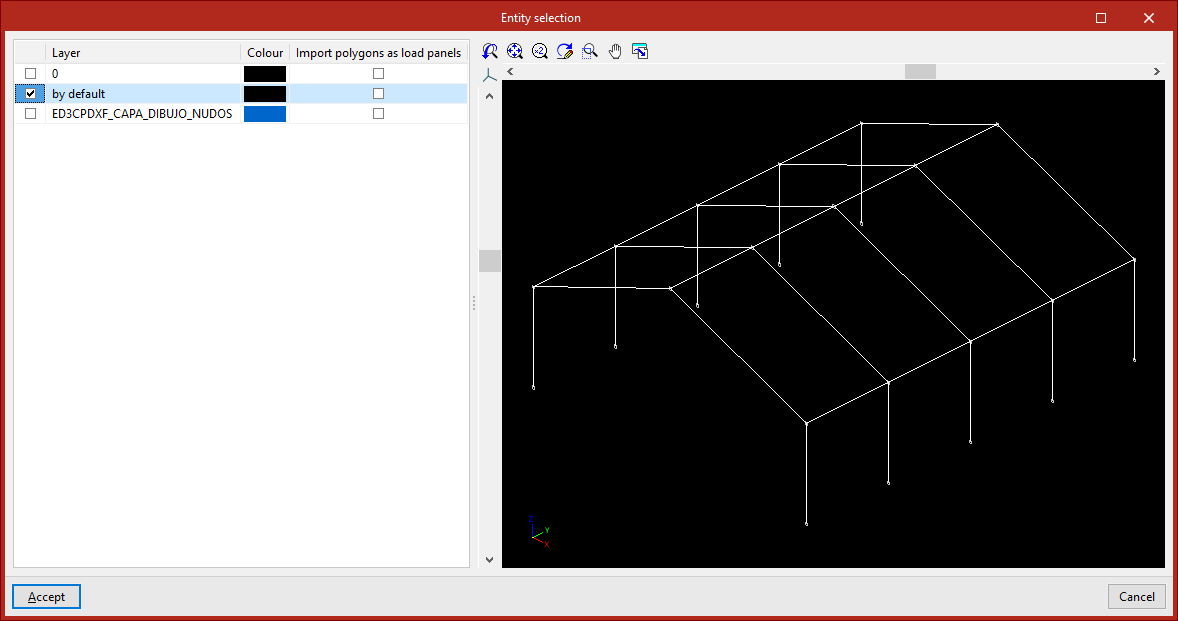
Once you have selected and loaded the file, the "Entity selection" window appears.
The table on the left shows each "Layer" in the drawing and its "Colour". The viewer on the right allows you to view the elements contained in the file.
In the first column of the table, tick the relevant boxes to select the layers in the file that contain the elements you wish to import. When you do so, the elements assigned to each layer change colour in the viewer so that they can be easily identified.
You should check the "Import polygons as load panels" box if you wish to import the polygons contained in that layer as panels, and uncheck it if you wish to import them as sheets.
| Note: |
|---|
| You should only activate the layers containing lines that represent members, panels and/or sheets of the structure. These lines must have been entered accurately into the original program to ensure that the correct number of bars, panels and/or sheets is generated, with the correct dimensions and positioning. There is no need to import layers containing other types of information, such as text, details and symbols. |
Then click "Accept".
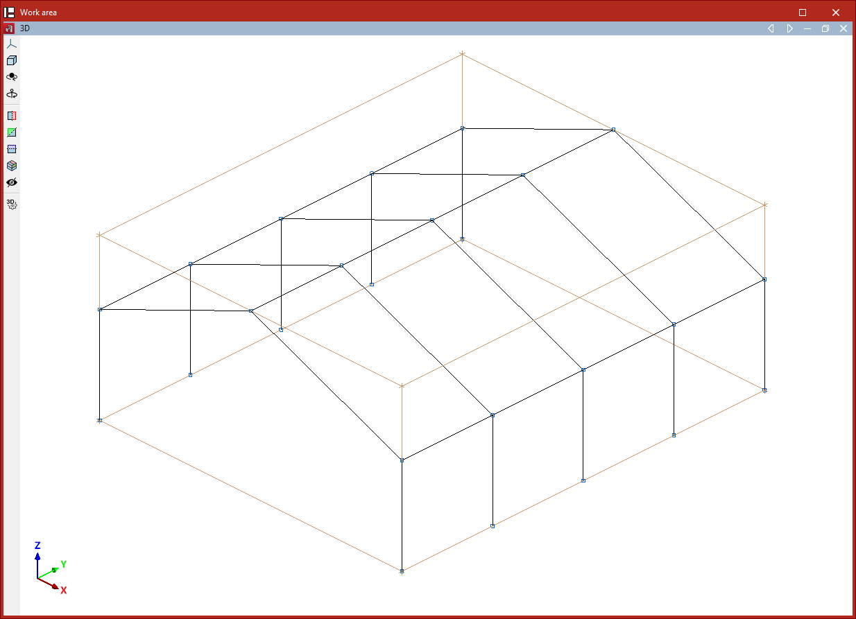
The program will read the lines in the drawing and convert them into beam-type elements, and will read and convert the polygons into slab-type elements, depending on the defined settings. If any elements cannot be imported, this will be indicated by a warning message.
During import, labels are created with the same name and colour as the existing layers in the .dxf or .dwg file. To manage these, use the "Labels" panel on the left-hand side. Imported elements are assigned to the same layer to which they were assigned in the .dxf or .dwg file.
Once the import is complete, you will need to define the sections of the elements and the external connections, and enter the loads and any other information required to complete the model.
Layout of the elements imported into the model
If the project is empty at the time of import, the program will import the elements into the position specified in the file.
If the project contains any elements at the time of import, the program allows you to specify a reference point for inserting the geometry of the imported structure.
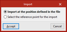
In this case, after clicking "Accept" in the "Entity selection" dialogue box, the program offers two options:
- The first option is "Import at the position defined in the DXF or DWG file".
- The second option allows you to "Select the reference point for the import". If you tick this option, after clicking "Accept" you can left-click to specify the position of the import reference point in space.