Generating geometry by importing text files
The geometry of the structure can be generated automatically in CYPE 3D from a text file. To do this, use the “Text file” option, available in the “Import” section of the top toolbar, within the “Geometry” tab (under the “Structure” tab).

Text file format
The program can import nodes, beams and shells from text files (with the .txt extension) in the following format:
- At the start of the text file, write the word NODES or JOINTS to define the nodes. On the next line, enter the node number, a space, the letter X, the = symbol, and the numerical value of the X-coordinate. Leave a space, then repeat the process for the node’s Y and Z coordinates. Each node is defined on a separate line.
- Next, the beams are defined by first typing the word BEAMS or FRAMES. Then, a beam is defined on each line by typing the beam number, a space, the starting node number, another space, and the ending node number.
- The shells are defined later, with the sequence titled using the word SHELLS. Similarly, each shell is defined on a separate line by entering the shell number, a space, and the node numbers that constitute the shell’s vertices, separated by spaces.
- Finally, the load panels are defined by typing the word PANELS. Each load panel is then defined on a separate line by typing the panel number, a space, and the node numbers that make up the panel, separated by spaces.
An example is shown on the right. You can download the corresponding .txt file via this link.
JOINTS
1 X=0 Y=0 Z=0
2 X=0 Y=0 Z=3
3 X=5 Y=0 Z=5
4 X=10 Y=0 Z=0
5 X=10 Y=0 Z=3
6 X=0 Y=3 Z=0
7 X=0 Y=3 Z=3
8 X=5 Y=3 Z=5
9 X=10 Y=3 Z=0
10 X=10 Y=3 Z=3
FRAMES
1 1 2
2 2 3
3 3 5
4 4 5
5 6 7
6 7 8
7 8 10
8 9 10
SHELLS
1 2 3 8 7
2 3 5 10 8
PANELS
1 2 3 8 7
2 3 5 10 8
Importing the text file
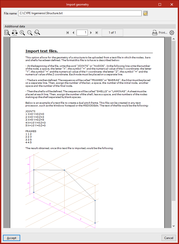
When you click on the option, the "Import geometry" window opens.
Here, if you have a file in the specified format, click the relevant button to the right of the "File name" field at the top to locate it on your hard drive.
The help text under the "Additional data" section specifies the format the text file must follow and also includes an example.
Once you have selected and opened the file, click "Accept".
The program indicates whether the "Reading finished correctly" and asks "Do you wish to import read data".
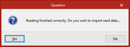
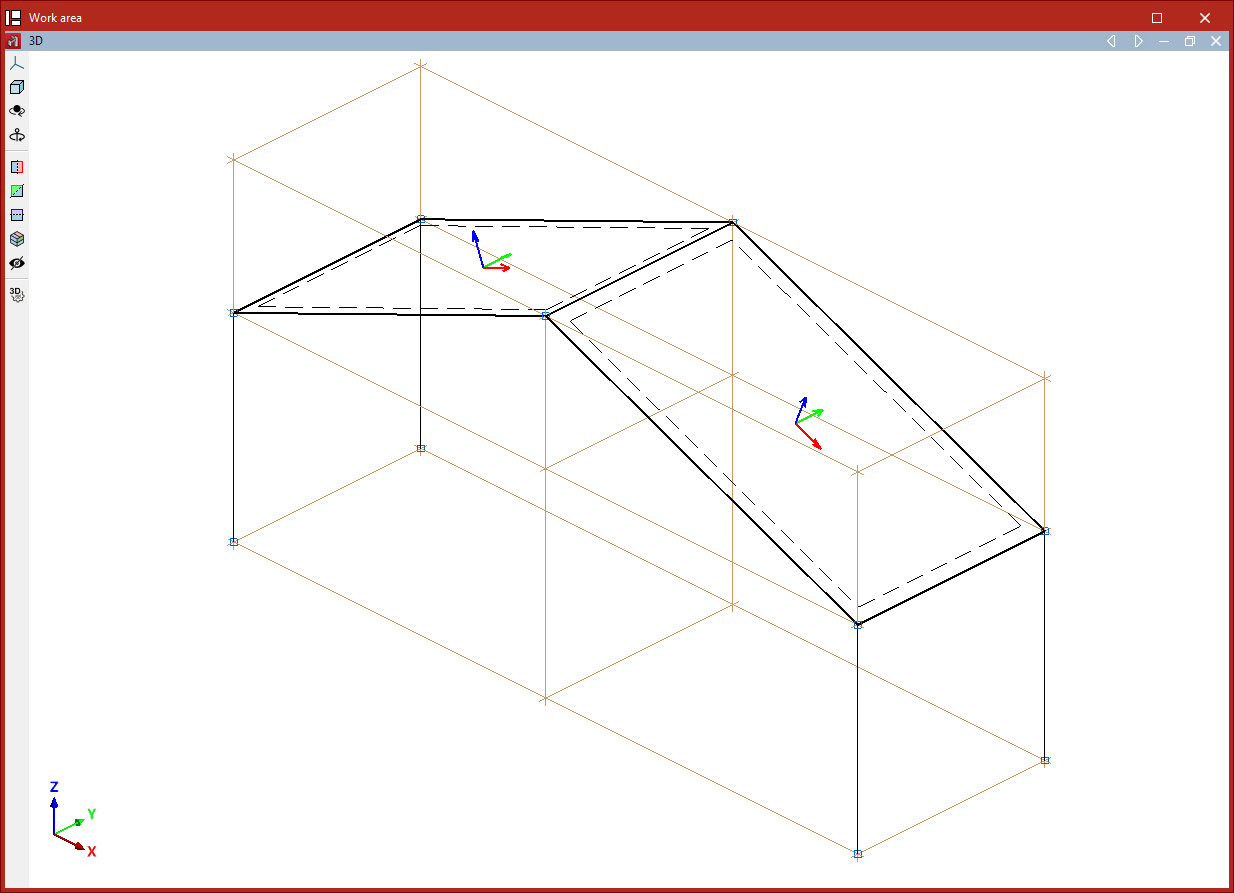
If you select "Yes", the program will import the elements into the model.
| Note: |
|---|
| The dimensions of the imported structure will depend on the unit system used (under "Settings", "Units"). The values in the .txt file will be treated as being expressed in the selected units. |
From this point onwards, the cross-sections of the beams and slabs, the loads, and the external and internal connections must be defined in order to complete the project.
Layout of the elements imported into the model
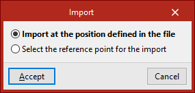
If the text file is imported into a project that is not empty, the program will allow you to choose the position of the imported elements:
- If you select "Import to the position specified in the file", the program will load the data at the coordinates entered in the file.
- If "Select reference point for import" is displayed, you must select that point by clicking on it with the left mouse button directly in the model view.