Inserting and editing force integration strips in shells
Force integration strips can be added and edited in shells using the "Integration strips" option, which is available in the "Shells" section of the top toolbar, within the "Properties" tab (under the "Structure" sub-tab).

The integration strips in the plates define lines along which, for a given bandwidth, the forces corresponding to the plate are integrated to obtain the bar forces.
Integration strips
After clicking on the option, select the slides using the left mouse button or by dragging to select a capture area, then click the right mouse button to confirm.
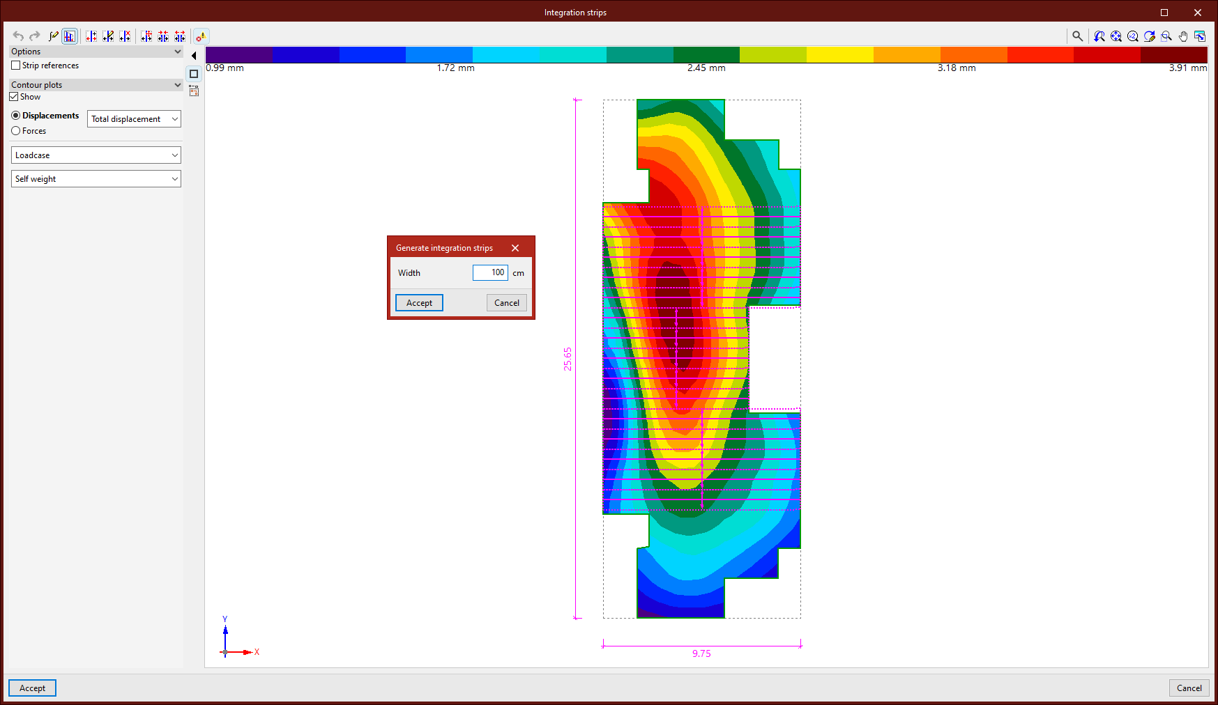
The geometry of the first selected sheet is displayed in the centre of the pop-up window. If more than one shell has been selected, once editing is complete, the integration strips are copied to the remaining selected shells.
Display options
On the left-hand side, the program allows you to display the "Strip references" once they have been entered, as well as the "Contour plots" for "Displacements" and "Forces" if the structure has been analysed. You can also enable "Screenshots" here.
Configuring the integration of forces in strips
The first button on the top toolbar allows you to define the "Integration of forces in strips". This can be set to "Based on the internal forces", in which case you can "Use smoothed forces" by ticking the relevant box, or "Based on the nodal forces". A detailed explanation of these methods can be found in the "Help" section, which can be accessed by clicking the button on the title bar of this window.
Generating integration strips
The following button allows you to "Generate integration strips in the zone". First, enter the "Width" of the strips. Then, after clicking "Accept", use the left mouse button to select four points that define the generation area. The integration strips are parallel to the line defined by the first two points selected and will be generated within the zone, taking into account the geometry of the sheet.
Issues
The last option on the top toolbar allows you to "Show/Hide issues" for elements where an error has occurred. If you hover the cursor over these elements, the program displays a message describing the error.
Introduction and manual editing of integration strips
The other options on the top toolbar allow you to enter and edit integration strips manually:
- Use the "New" option to insert a new integration strip. To do this, after entering the "Width" and clicking "Accept", select two points on the image using the left mouse button.
- From the "Edit" menu, you can modify the properties of several integration strips simultaneously. To do this, select the strips using the left mouse button or highlight a capture area, then right-click. In the pop-up window, adjust the "Width" and the "Number of force points".
- Use this option to "Delete" a group of integration strips. Similarly, select the strips using the left mouse button or by dragging to create a selection area, then click the right mouse button to confirm.
- The "Move end" function moves the end of an integration strip. To do this, left-click to select the end of the band, and then select its new position.
- It is also possible to "Join" several integration strips. After clicking on the option, select several parallel strips using the left mouse button or by dragging to define a selection area, then confirm with the right mouse button. This creates a single integration band within the area defined by the selected bands.
- To "Divide" multiple integration strips, click on the relevant option and then select the strips using the left mouse button or by dragging to select an area. Right-click, enter the "Number of divisions" in the dialog box, and click "Accept". Multiple integration strips will be generated in place of each selected strip.
To finish editing the integration strips and confirm the changes, click "Accept".
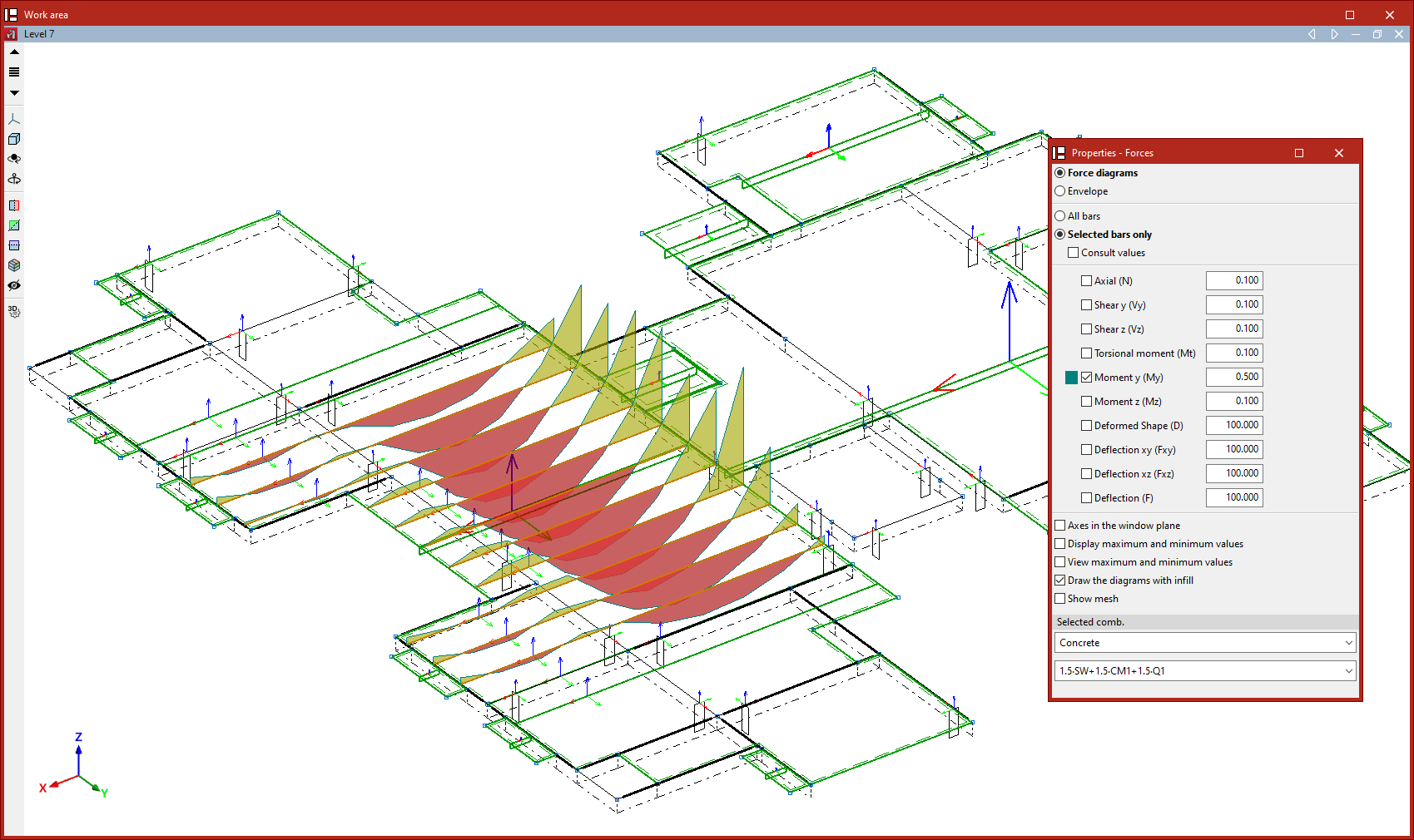
Checking forces in integration strips
Creating integration strips allows you to view the forces in each strip as if they were the forces acting on a structural beam.
To do this, once the structural analysis has been carried out, use the "Forces" option in the "Stress / Strain" group on the "Analysis" tab.