Entering and editing load panels
Load panels can be entered and edited using the following options, available in the "Panels" group on the top toolbar, under the "Load" tab (in the "Structure" tab).

In the program, a panel is a closed polygon that distributes the loads applied to its surface. These loads can either be defined directly when editing the panel, or they can be surface loads whose geometry lies within the panel’s area.
Load distribution is applied to structural elements whose geometry overlaps with that of the panel:
- On the bars located within the panel area and whose direction has a component perpendicular to the distribution direction defined in the panel.
- On the shells whose geometry coincides with or overlaps that of the panel.
The effect is equivalent to entering loads on bars or shells, with the added advantage that the program automatically calculates the value of the load to be applied to each element.
New
To enter panels, select the "New" option.
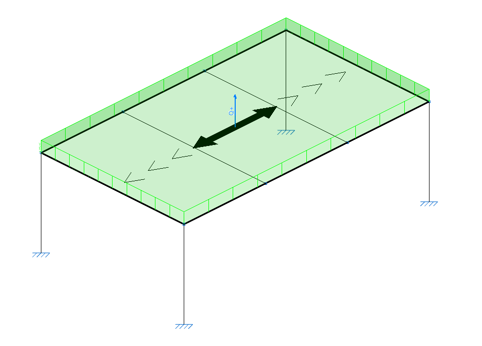
Defining the panel’s outline
After selecting the option, click with the left mouse button on the points of a closed polygon to define its outline.
Then, right-click to confirm.
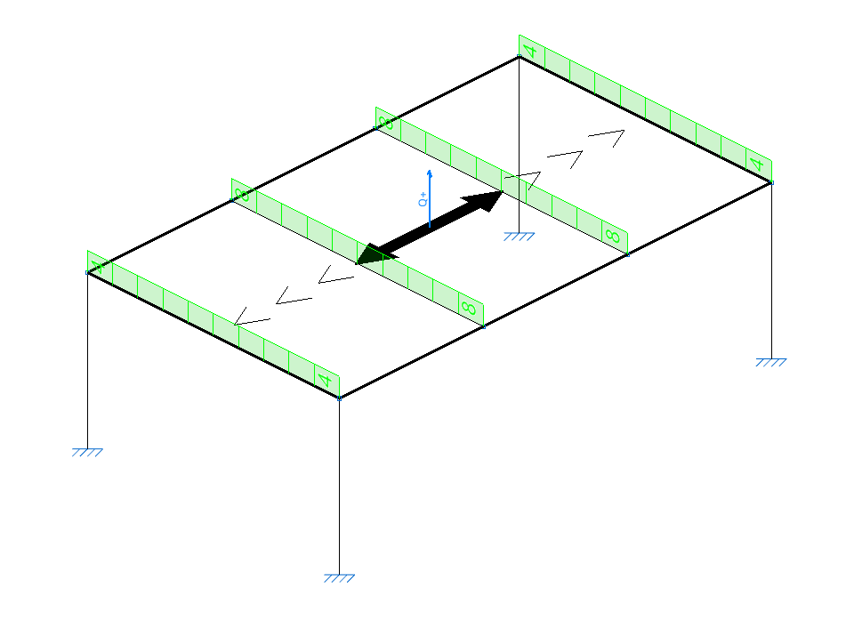
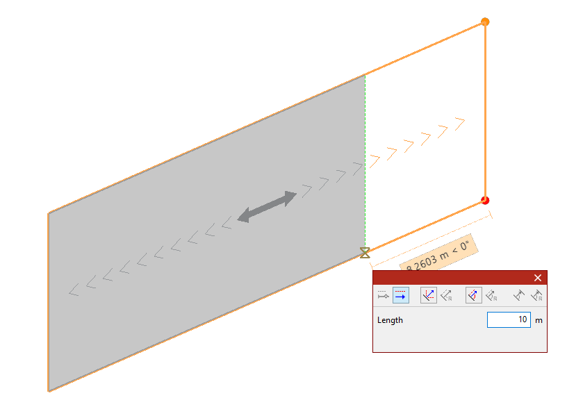
Defining the distribution direction
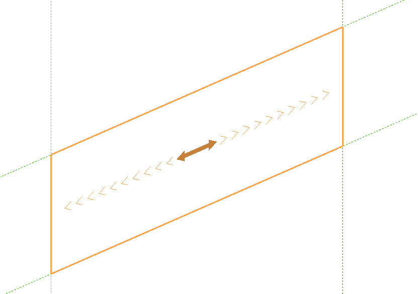
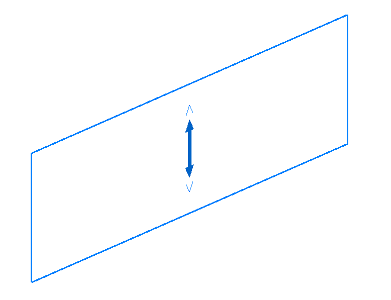
After defining the panel’s outline, you must specify the load distribution direction by left-clicking one of the auxiliary lines located on either side of the panel.
The distribution direction will be "Parallel to the selected side" or "Perpendicular to the selected side", depending on the selection made in the "Load distribution direction" drop-down menu in the "Properties" pop-up window.
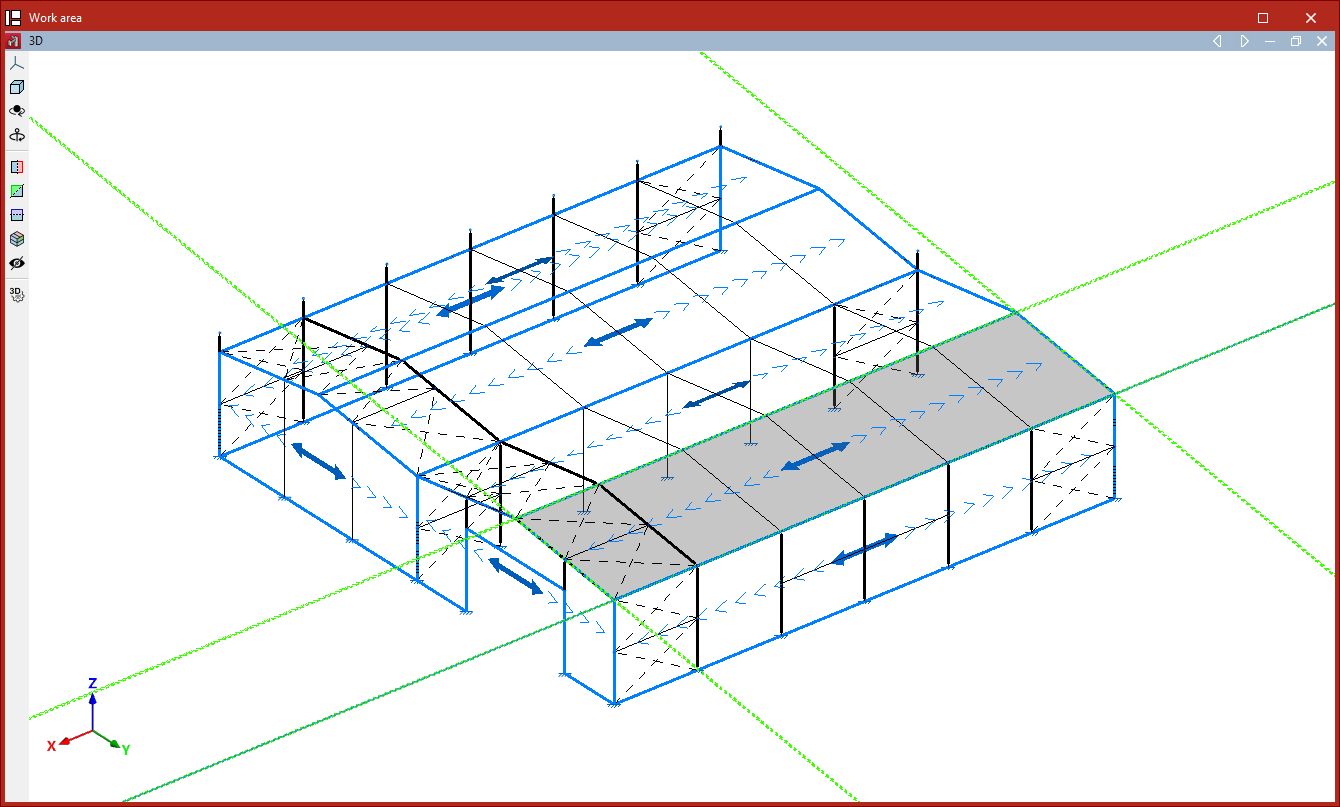
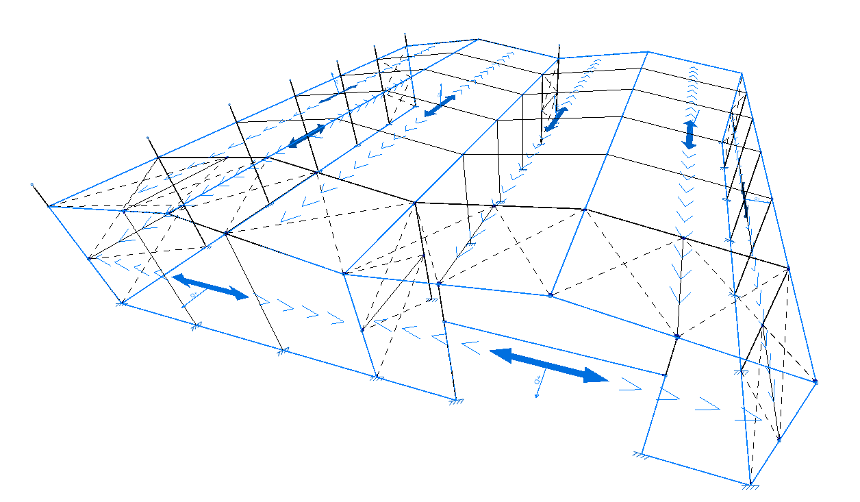
| Example: |
|---|
| To create a panel on a roof slope, select its four vertices to define the outline. As the program will apply the load to the bars perpendicular to the distribution direction, if you wish to apply the load to the transverse frames, the distribution direction is that of the chords; therefore, select an auxiliary line parallel to them (by ticking the "Parallel to selected side" option). |
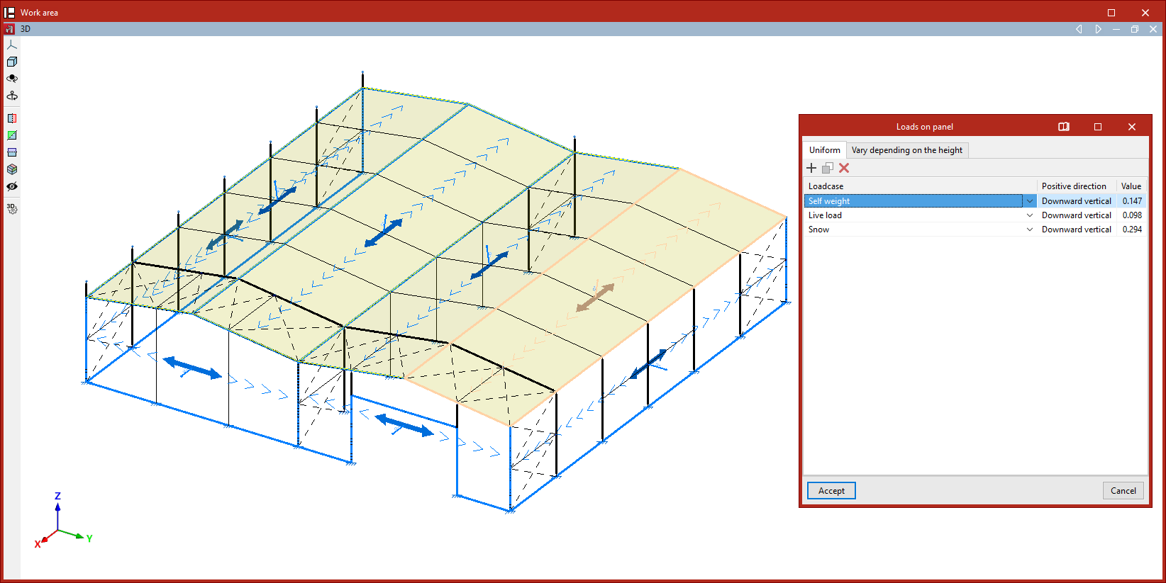
Loads on panel
After defining the panel’s outline and distribution direction, right-click to open the "Loads on panel" window, where one or more loads can be added to the panel under different load cases.
These loads are applied across the entire surface of the panel. If you want to apply loads to only part of the panel, you can leave this table empty and later draw surface loads on the panel’s geometry.
If the panel is not parallel to the global XY plane, two tabs are shown: one for "Uniform" loads and another for loads that "Vary depending on the height". If the panel is horizontal, only the "Uniform" load table is displayed.
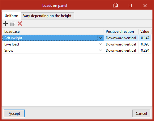
Uniform loads
The options at the top allow you to "Add", "Copy", and "Delete" loads. To enter a load, click "Add" and select the "Load case" from the dropdown menu.
Then, check the "Positive direction" of the loads, which is automatically determined based on the selected load case.
Loads associated with wind load cases are applied perpendicular to the panel. In this case, the program shows the coordinates of a unit vector representing the direction of a positive load.
Loads from other load cases are applied vertically along the global Z-axis. By default, the positive direction is "Vertical downwards".
Finally, enter the "Value" of the load, which may be positive or negative depending on the direction of application.
For "Uniform" loads, a single value is defined for the entire surface.
Loads that vary depending on the height
For loads that "Vary depending on the height", in addition to the "Load case" and "Positive direction", you must specify two values: the "Value at the lower level" and the "Value at the upper level" of the panel’s surface.
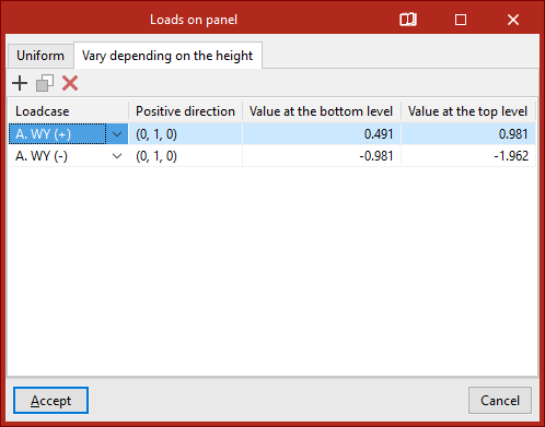
After clicking "Accept", the program will insert the panel into the model.
Edit
The "Edit" option allows you to edit loads on previously inserted panels.
After selecting the option, choose one or more panels and right-click.
This opens the "Loads on panel" window, where the loads applied to the selected panels can be modified.
| Note: |
|---|
| If multiple panels are selected, the information displayed in the "Loads on panel" window corresponds to the first panel selected; therefore, when confirming, the loads can be matched across all selected panels. |
Delete
The "Delete" option removes the selected panels and their associated surface loads. To do this, select the panels using the left mouse button, and delete by right-clicking.
Move
The "Move" option modifies the geometry of the polygon defining the panel as follows:
- Select the panel using the left mouse button.
- Then click on the vertices of the polygon you want to move.
- Right-click to confirm the selection of these points.
- Left-click to select a reference point for the displacement, and then click on the target point to move the reference.
- Confirm the operation by right-clicking again.
The result is a panel with modified geometry.
Divide
The "Divide" option allows you to divide a panel by inserting a division line between two points in the work area.
The program will generate two independent panels after the operation.
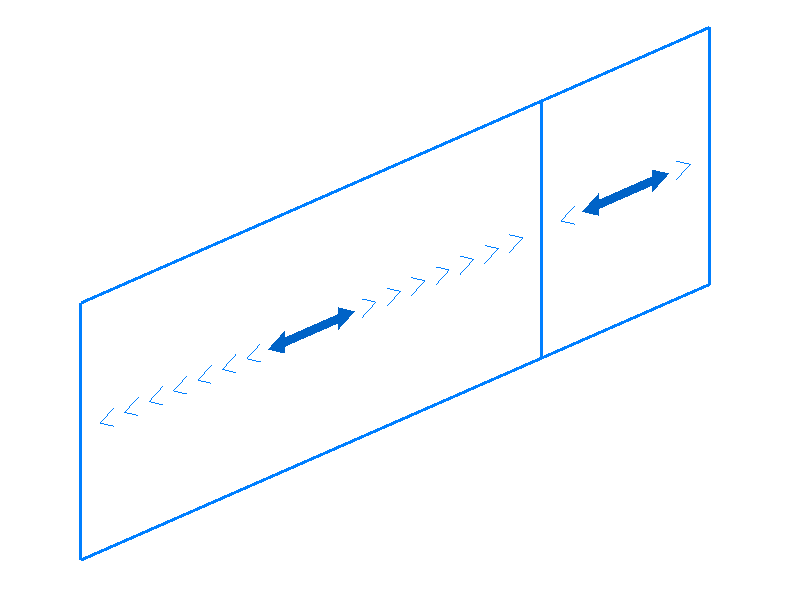
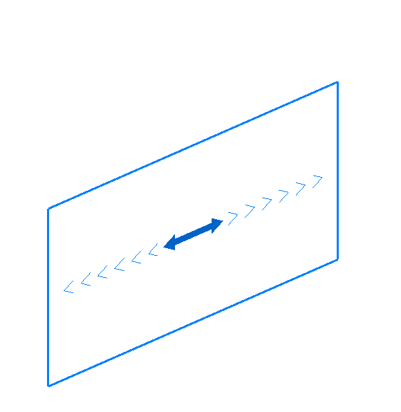
Distribution direction
The "Distribution direction" option allows you to modify the load distribution direction of a panel using the following steps:
- Select the panel using the left mouse button.
- Indicate the new direction by clicking on one of the auxiliary lines along the sides of the panel (visible when using this option).
The distribution direction will be "Parallel to the selected side" or "Perpendicular to the selected side", depending on the selection made in the "Load distribution direction" drop-down menu in the "Properties" pop-up window.