
Inserting and editing loads on shells
Loads on shells can be entered and edited using the following options, which are available in the "Shells" section of the top toolbar, within the "Load" tab (under the "Structure" tab).

New
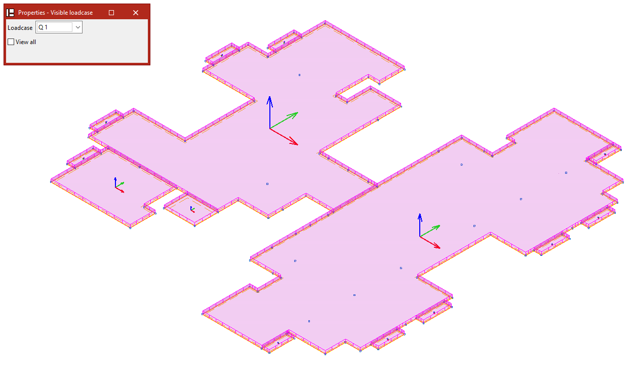
The "New" option allows you to enter new loads for a group of shells. Clicking on this option opens the "Properties – Visible loadcase" window, where you can select the "Loadcase" you wish to view. You can also "View all" loadcases by ticking the relevant box.
Next, click on the shells one by one using the left mouse button, or select a capture area.
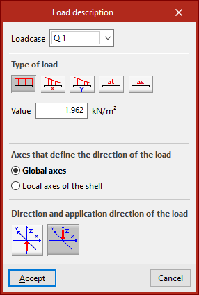
Right-clicking opens the "Enter loads on shells" window. In this window, you must first select the "Loadcase" to which you wish to assign the new loads.
Next, select the "Load type". The options available for "Load type" include the following:
- Uniform load
When selecting this type of load, you must enter its "Value". - Variable load in the local x axis
- Variable load in the local y axis
In the case of variable loads, you must enter both the "Initial value" and the "Final value". - You can also enter a "Increase in uniform temperature" or specify a "Retraction" value.
Surface loads defined in this way are applied across the entire surface of the shell.
The central section specifies the "Axes that define the direction of the load". These may be:
- the "Global axes";
- or the "Local axes of the shell".
The "Direction and application direction of the load" is indicated below. The following may be used:
- "Direction along the Z-axis, in the positive direction";
- or "Direction along the Z-axis, in the negative direction".
Once you click "Accept", the program will apply the load to the selected shells.
The remaining options in the "Shells" section allow you to edit the loads on the shells:
Edit
To edit entries that have already been made, use the "Edit" option.
Select the "Loadcase" to which the loads you wish to edit are assigned, so that they become visible in the model. Then select the loads by clicking on them one by one or by selecting an area.
When you right-click, the "Load description" window appears, where you can edit the load data. The same options are available as when you enter the loads. Finally, click "Accept".
Delete
The "Delete" option allows you to remove loads from selected layers in the model. Left-click on the loads to select them, or draw a selection area and then right-click to remove them.
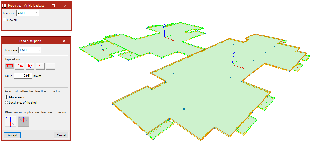
Loadcase
If you only need to modify the loadcases, use the "Loadcase" option.
Select the items you wish to edit and right-click.
In the "Loadcase" window, select the loadcase to which the loads will be assigned from the drop-down menu, then click "Accept".
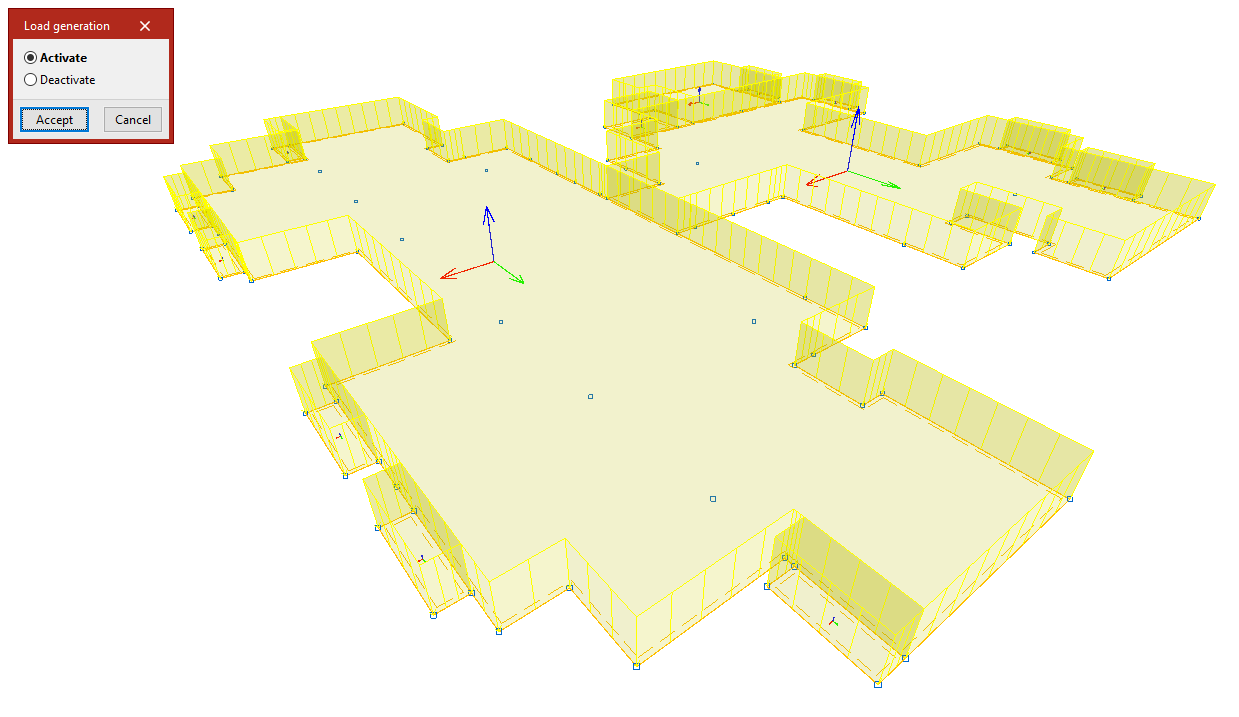
Dead weight
The "Self-weight" option enables or disables the automatic generation of self-weight loads for the shells. Clicking on it opens the "Load generation" dialogue box, where you can select "Activate" or "Deactivate".
By default, the program calculates the dead loads for the slabs and displays them on screen.
If you select an action, such as "Deactivate", the shells will be selected after you click "Accept". Right-click to remove the associated self-weight loads. Right-clicking again brings up the "Load generation" dialogue box, allowing you to change the action to be performed.
Applying loads to shells using panels and surface loads
There is another way of applying loads to plates, which involves placing the plate within the area of a load panel. In this case, the panel must be completely covered by shells. Furthermore, the shells pick up any surface loads defined on the panel.
To enter and edit these loads, use the tools available in the "Load" tab relating to panels and surface loads.