Plastic hinge library
You can access the plastic hinge library using the following option, which is available in the "Project" section of the top toolbar, within the "Project" tab (under the "Structure" sub-tab).

The plastic hinges created here can be selected and used when inserting plastic hinges into bars via the "Plastic hinges" option in the "Bars" tab.
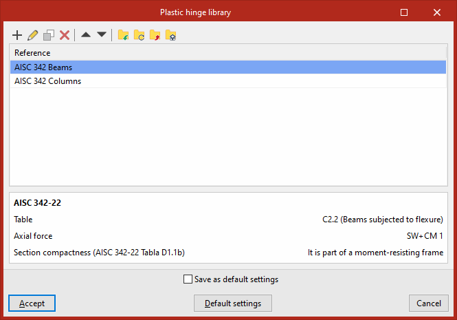
List of plastic hinges
The list of plastic hinges that appears when you open the "Plastic hinge library" features a series of options at the top for "Add", "Edit", "Copy", "Delete" and reordering hinge types, as well as for importing and exporting the elements defined here to files on the hard drive.
When defining the properties of each plastic hinge, you must specify a "Reference" and choose between two types:
- Linear elastic hardening
- Modified Ibarra-Medina-Krawinkler
- Generic (defined by sections)
- AISC 342-22
- ACI 369.1-22
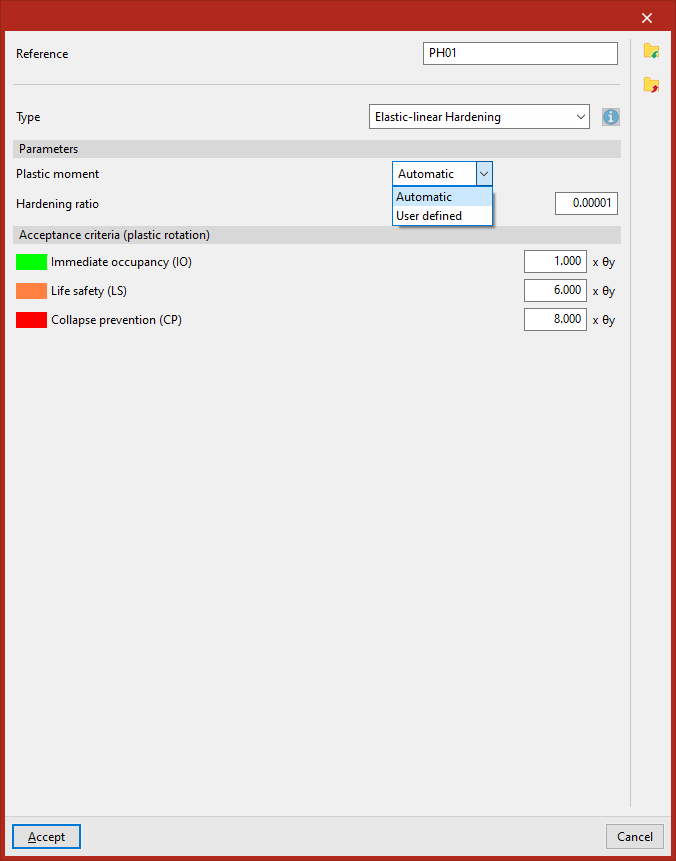
Hinges with elastic-linear hardening
The data required to define the behaviour of a plastic hinge with "Elastic-linear hardening" are the "Plastic moment" and the "Hardening ratio" (or slope in the plastic span).
In the "Yield point" drop-down menu, you can choose to have the program calculate this value automatically – which is possible for steel sections with a known plastic modulus – or enter it manually in all other cases.
The "Acceptance criteria (plastic rotation)" section defines the following states by specifying a factor that multiplies the plastic rotation θy:
- Immediate occpancy (IO)
- Life safety (LS)
- Collapse prevention (CP)
The program will use the colours associated with each state to highlight the tags that have reached that state in the force display.
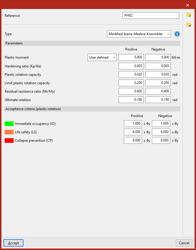
Ibarra-Medina-Krawinkler hinges
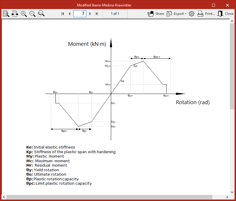
"Modified Ibarra-Medina-Krawinkler" type plastic hinges allow the behaviour of resistance and stiffness reduction following plasticisation to be modelled using a backbone curve.
The data required to define the behaviour of a plastic hinge in a given degree of rotational freedom are as follows:
- Plastic moment (Positive, Negative)
- Hardening ratio (Kp/Ke) (Positive, Negative)
- Plastic rotation capacity (Positive, Negative)
- Limit plastic rotation capacity (Positive, Negative)
- Residual resistance ratio (Mr/My) (Positive, Negative)
- Ultimate rotation (Positive, Negative)
The "Acceptance criteria (plastic rotation)" section defines the following states by specifying a factor that multiplies the plastic rotation θy:
- Immediate occpancy (IO)
- Life safety (LS)
- Collapse prevention (CP)
The program will use the colours associated with each state to highlight the tags that have reached that state in the force display.
The data entry panel features a help button that displays the hinge’s performance curve and a key explaining the parameters that define it.
Generic (defined by spans)
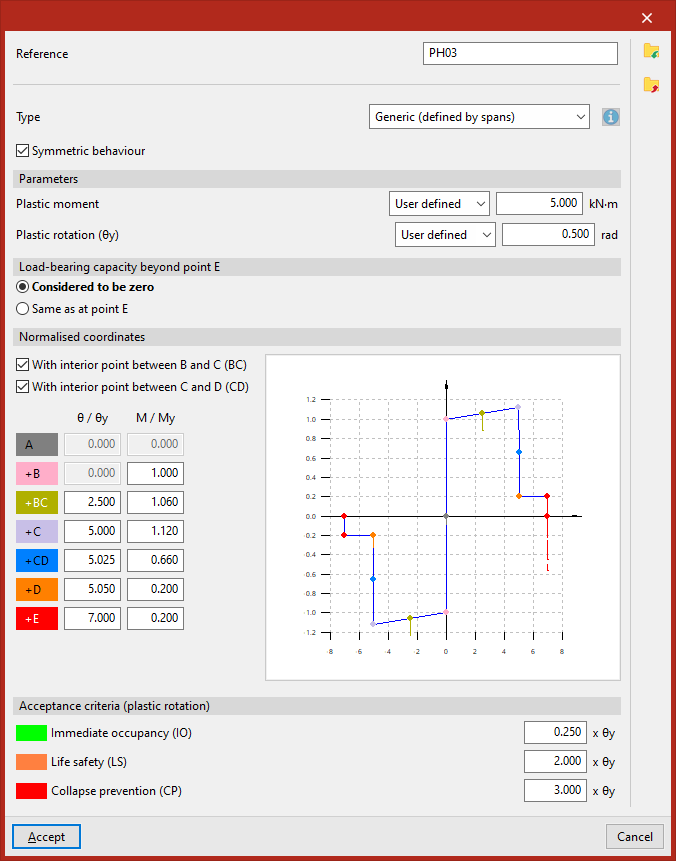
"Generic (defined by spans)" plastic hinges allow users to freely model the moment-rotation curve in spans between points designated by letters (A, B, C, D, E).
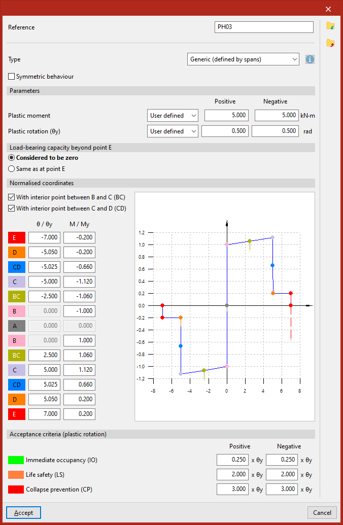
Firstly, you must tick or untick the "Symmetric behaviour" box to specify whether the positive and negative sections are symmetric or not.
In the "Parameters" section, in the drop-down menus "Plastic moment" and "Yield rotation (θy)", you can choose to have the program calculate these values automatically—which is possible for steel sections with a known yield modulus—or enter them manually in all other cases.
The "Load capacity beyond point E" is "considered to be zero" or "the same as at point E", depending on the option selected.
Next, in the following section, you must enter the "Normalised coordinates" of the points that define the moment-rotation curve. To do this, enter the values for the moment and rotation relative to the yield moment and the yield rotation ("θ/θy", "M/My").
Optionally, you can tick the boxes "With an internal point between B and C (BC)" and/or "With an internal point between C and D (CD)" to set these intermediate points on the curve and enter their coordinates.
For hinges with symmetrical behaviour, simply specify the values for the following points:
- At (θ/θy = 0, M/My = 0)
- +B (θ/θy = 0, M/My user-defined)
- +BC (θ/θy, M/My user-defined)
- +C (θ/θy, M/My user-defined)
- +CD (θ/θy, M/My user-defined)
- +D (θ/θy, M/My user-defined)
- +E (θ/θy, M/My user-defined)
For hinges that do not operate symmetrically, the following values are specified:
- For the negative part of the curve:
- E (θ/θy, M/My defined by the user)
- D (θ/θy, M/My defined by the user)
- CD (θ/θy, M/My defined by the user)
- C (θ/θy, M/My defined by the user)
- BC (θ/θy, M/My defined by the user)
- B (θ/θy = 0, M/My defined by the user)
- At (θ/θy = 0, M/My = 0)
- For the positive part of the curve:
- At (θ/θy = 0, M/My = 0)
- B (θ/θy = 0, M/My defined by the user)
- BC (θ/θy, M/My defined by the user)
- C (θ/θy, M/My defined by the user)
- CD (θ/θy, M/My defined by the user)
- D (θ/θy, M/My defined by the user)
- E (θ/θy, M/My defined by the user)
The section entitled "Acceptance criteria (plastic rotation)" defines the following states by specifying a factor that multiplies the plastic rotation θy:
- Immediate occpancy (IO)
- Life safety (LS)
- Collapse prevention (CP)
The program will use the colours associated with each state to highlight the tags that have reached that state in the force display.
AISC 342-22
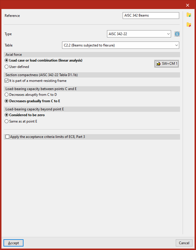
"AISC 342-22" type plastic hinges comply with the specifications set out in this standard.
In the "Table" drop-down menu, you can select the entries "C2.2 (Beams under bending)" or "C3.6 (Columns under bending with a compression or tension axis)".
The "Axial force" can be entered using a "Load case or load combination (linear analysis)", for which you must click on the edit button on the right and define the list of "Loadcases" and the combination "Factor" for each one, or it can be "User-defined" by entering the value directly.
As for the "Section compactness (AISC 34-22 Table D1.1b)", you can tick the relevant box to indicate that the hinge "Is part of a moment-resisting frame".
It is also possible to specify whether the "Load-bearing capacity between points C and E" "decreases abruptly from C to D" or "decreases gradually from C to E".
Similarly, the "Load-bearing capacity beyond point E" is "considered to be zero" or "the same as at point E", depending on the option selected.
Finally, you can tick the last box to "Apply the acceptance criteria limits of EC8, Part 3" by selecting the "Section class" ("Class 1" or "Class 2").
ACI 369.1-22
Plastic hinges of the "ACI 369.1-22" type comply with the specifications set out in this standard.
In the "Table" drop-down menu, you can select the joints from "Table 4.2.2.2.2a (Reinforced concrete beams)" or "Table 4.2.2.2.2b/c (Reinforced concrete columns)".
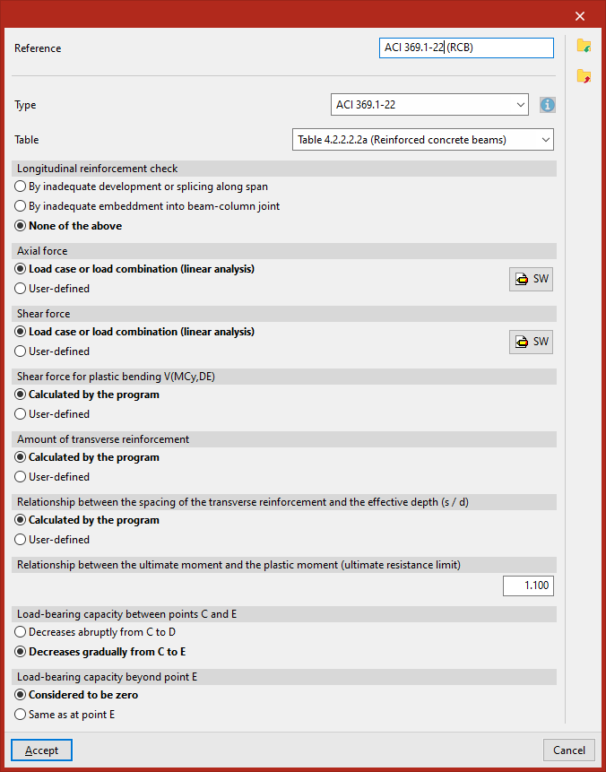
Hinge connections in Table 4.2.2.2.2a (Reinforced concrete beams)
In these hinges, the "Longitudinal reinforcement check" may be "By inadequate development or splicing along span", "By inadequate embedment beam-column joint", or "None of the above".
The "Axial force" and "Shear force" in their respective sections can be entered using a "Load case or load combination (linear analysis)", for which you must click on the edit button on the right and define the list of "Load cases" and the combination "Factor" for each one, or set each one to "User-defined" by entering its value directly.
The "V(MCy,DE) flexural plasticity shear modulus" can be either "Calculated by the program" or "User-defined".
The "Cross-section reinforcement quantity" can also be a value "Calculated by the program" or "User-defined".
Similarly, the "Relationship between the spacing of the transverse reinforcement and the effective depth (s/d)" can be either "Calculated by the program" or "User-defined".
You must enter the value of the "ratio of ultimate stress to yield stress (ultimate strength limit)".
Further on, you can specify whether the "Load-carrying capacity between points C and E" "Decreases abruptly from C to D" or "Decreases gradually from C to E".
Finally, the "Load-carrying capacity beyond point E" is "Considered to be zero" or "Same as at point E", depending on the selected option.
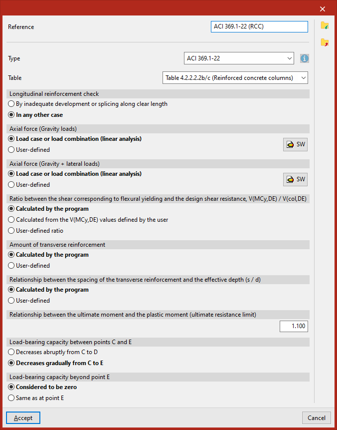
Hinge joints in Table 4.2.2.2.2b/c (Reinforced concrete columns)
In these hinges, the "Longitudinal reinforcement control" may be "By inadequate development or splicing along clear length" or "In any other case".
The axial stress for gravitational loads and the axial stress for gravitational and lateral loads (defined in the sections "Axial force (Gravity)" and "Axial force (Gravity + lateral)" can be entered via a "Load case or load combination (linear analysis)", for which you must click on the edit button on the right and define the list of "Load cases" and the combination "Factor" for each one, or set each one to "User-defined" by entering its value directly.
The "Ratio between the shear corresponding to flexural yielding and the design shear resistance V(MCy,DE) / V(col,DE)" can be "Calculated by the program", or "calculated from the V(MCy,DE)", or be a "User-defined ratio" (in these two cases, enter the values "Vy" and "Vz").
The "Amount of transverse reinforcement" can also be "Calculated by the program" or "User-defined".
Similarly, the "Relationship between the spacing of the transverse reinforcement and the effective depth (s/d)" can be "Calculated by the program" or "User-defined".
You must enter the value of the "Relationship between the ultimate moment and the plastic moment (ultimate resistance limit)".
Further on, you can specify whether the "Load-bearing capacity between points C and E" "Decreases abruptly from C to D" or "Decreases gradually from C to E".
Finally, the "Load-bearing capacity beyond point E" is "Considered to be zero" or "Same as at point E", depending on the option selected.