
Defining load cases for the pushover analysis
Load cases for pushover analysis are created and edited using the "Load cases" option, available in the "Pushover" section of the top bar, within the "Analysis" tab (under the "Structure" sub-tab):

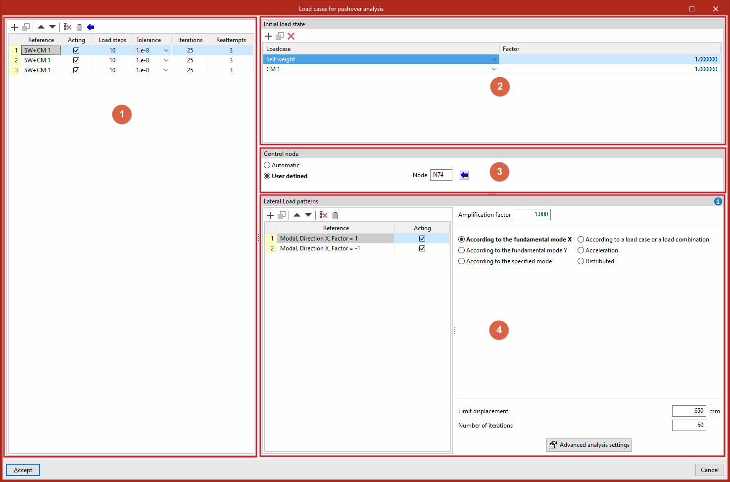
For each load case in the list (1), the following is defined:
- the "Initial load state" (2),
- the "Control node" (3),
- and the "Lateral load patterns" (4).
Load cases
The "Load cases" option is used to define the load cases for the pushover analysis.
Clicking this opens the "Load cases for pushover analysis" window. These load cases must be added to the list on the left-hand side using the options on the top toolbar. Each load case is defined as follows:
- The "Reference" is generated automatically based on the load cases and combination factors defined below.
- Indicate whether the case is "Acting" or not by ticking the relevant box.
- Several "Load steps" are defined, the "Tolerance" value is selected, and the number of "Iterations" used in the analysis and the number of "Reattempts" are entered.
Alternatively, you can also click the assistant button at the top of the load case list to "Import the load cases defined for the modal analysis".
Initial load status
Next, in the top-right-hand corner, the "Initial load state" is defined for each load case selected from the list.
To do this, add entries to the list by selecting "Loadcase" from the drop-down menu and entering the value for "Factor" for each one.
Control node
The "Control node" section allows you to define the control node for each load case selected from the list in two ways:
- "Automatic", in which case the program will select a node located at the highest point of the structure, as close as possible to the geometric centre of that area, and whose degrees of freedom Dx and Dy are not constrained.
- or "User defined", in which case you must either enter the node reference directly or click the "Available nodes" button to select it from the list.
Lateral load patterns
For each selected load case, you must define the list of "Lateral load patterns" in the bottom right-hand corner.
Each load pattern must be entered into the pattern list, which displays its "Reference" (generated automatically) and allows you to specify whether it is "Active" or not.
Next, on the right-hand side, for each pattern, enter the "amplification factor" and select the lateral load distribution (FEMA 356, 3.3.3.2.3) from the following options (lateral loads will be applied to the mathematical model in proportion to the distribution of inertia forces):
- According to the fundamental mode X
A vertical lateral load distribution proportional to the shape of the fundamental mode in the X-direction will be applied. The "Limit displacement" and "Number of iterations" are specified.
- According to the fundamental mode Y
A vertical lateral load distribution proportional to the shape of the fundamental mode in the Y-direction will
be applied. The "Limit displacement" and "Number of iterations" are specified.
- According to the indicated moded
A vertical lateral load distribution proportional to the shape of the mode selected from the drop-down menu will be applied in the specified direction. Select the mode, specify the "Limit displacement" and the "Number of iterations", and select the "Monitored displacement" (Dx or Dy).
- Based on a loadcase or a load combination
The selected load combination will be applied as a lateral load distribution. The load combination is defined by entering assumptions and combination factors in a specific list, specifying the "Limit displacement" and the "Number of iterations", and selecting the "Monitored displacement" (Dx or Dy).
- Acceleration
A uniform distribution of lateral forces will be applied at each node, proportional to the node mass. Enter the "Acceleration" value, specify the "Limit displacement" and the "Number of iterations", and select the "Monitored displacement" (Dx or Dy).
- Distributed
A vertical distribution of lateral load proportional to the Cvx values (vertical distribution factor) will be applied. Select the "Type" of distribution from the following options, specify the "Limit displacement" and the "Number of iterations", and select the "Monitored displacement" (Dx or Dy):- Uniformly
In this particular formulation, the exponent 'k' is set to 0. - Triangular
The exponent 'k' is set to 1. - Parabolic
The exponent 'k' is set to 2.
- Uniformly
At the bottom of the page, you can access the "Advanced scan settings" for Pushover by clicking the relevant button.