Entering and editing surface loads
Surface loads can be entered and edited using the following options, available in the "Surface loads" group on the top toolbar, under the "Load" tab (in the "Structure" tab).

Surface loads may occupy all or part of the surface of a load panel, which can be inserted beforehand using the options in the "Panels" group, or alternatively, automatically generated when inserting the surface load. The panel will distribute the surface loads defined on it according to its distribution direction.
The distribution of surface loads is applied to the structural elements whose geometry overlaps with that of the panel:
- To bars that lie within the area of the panel and whose direction has a component perpendicular to the distribution direction defined in the panel.
- To shells whose geometry coincides with or overlaps the panel.
The effect is equivalent to applying loads on bars or shells, with the added benefit that the program automatically calculates the load value to be applied to each element.
New
The "New" option allows you to insert a new surface load in polygonal form.
To do so, follow these steps:
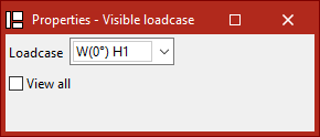
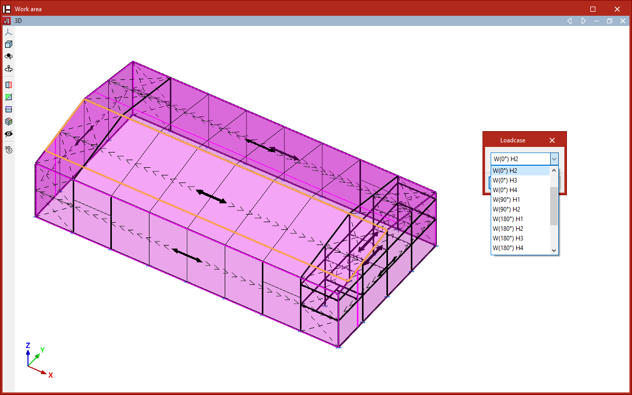
- Upon selecting the option, the "Visible load case" window appears. Here you can choose the "Load case" to be displayed on screen. You may also "Show all" load cases by ticking the corresponding box.
- Then, use the left mouse button to click the points that form the polygon contour of the surface load.
- Once done, right-click.
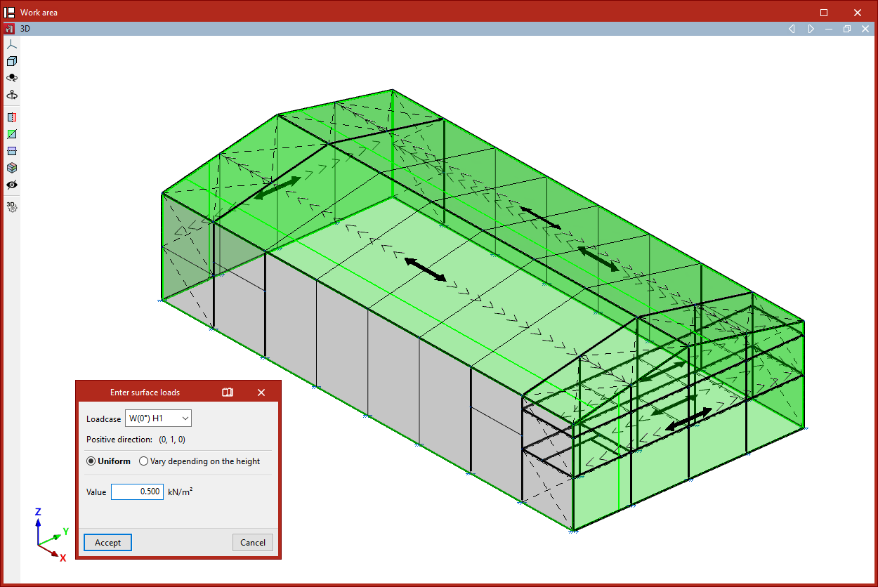
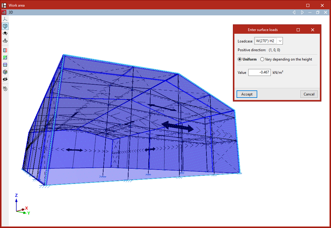
- This opens the "Enter surface loads" window:
- First, select the "Load case" to which the surface load will be assigned.
- The program also displays the "Positive direction" of the load, using the text "Vertical downwards" if the load is not part of a wind load case, or by showing the coordinates of a unit vector in the case of wind loads.
- The load can be either "Uniform" or "Height-varying" if the surface is not horizontal:
- For uniform loads, simply enter the "Value" and its sign.
- For height-varying loads, you must enter both the "Value at the upper level" and the "Value at the lower level". These correspond to the values and signs of the loads at the Z-coordinate of the top and bottom of the loaded surface.
- Finally, click "Accept".
Generating panels associated with surface loads
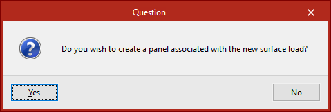
When a new surface load is inserted, the program checks whether it overlaps with an existing panel. If it does not, the user is asked whether a new panel should be created and associated with the new surface load.
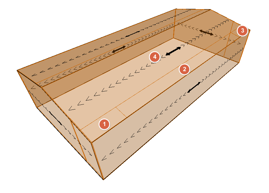
This new panel will have the same shape as the surface load and its distribution direction will be defined by the line joining the first two points of the surface load.
A surface load must belong entirely to a single panel, so a load cannot overlap more than one panel.
| Note: |
|---|
| Multiple surface loads with different geometries and values can be applied on a single panel. One practical example is creating wind pressure zones on a roof slope. |
Edit
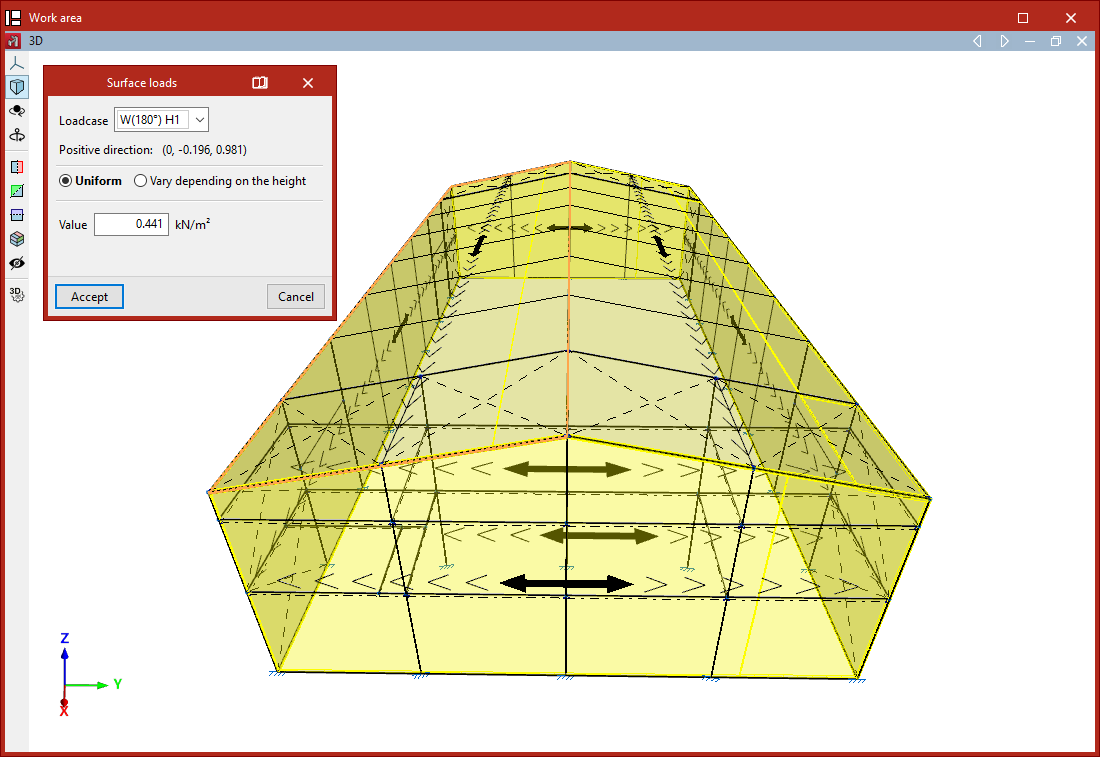
The "Edit" option allows you to modify the selected surface loads.
Only the loads associated with the "Visible load case" selected in the pop-up window are displayed.
Then, select the loads to be edited one by one with the left mouse button or by using a selection area, and right-click.The "Surface loads" window appears, where you can modify the load data. The program will apply the changes when you click "Accept".
Delete
The "Delete" option allows you to remove selected surface loads corresponding to the "Visible load case". After selecting the loads one by one or by using a selection area, right-click to delete them.
Load case
The "Load case" option allows you to edit the load case assigned to surface loads.
After selecting the loads and right-clicking, choose the "Load case" to assign to the loads.
Copy
The "Copy" option creates a new surface load by duplicating an existing one.
After selecting this option, choose a surface load. The "Enter surface loads" window will appear, where you can specify the "Load case", type, and values of the new surface load.
This new load will have the same shape and position as the existing one and will be generated in the same location.
| Note: |
|---|
| This option is useful for quickly creating loads of different load cases and values on the same surface (e.g. a façade or a roof slope). |
Move
The "Move" option allows you to change the shape and/or position of the polygon that defines a surface load.
- When selecting the option, the "Visible load case" window appears. You can choose the "Load case" to display or "Show all" by ticking the appropriate box.
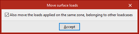
- Before continuing, right-click to access a dialogue where you can indicate whether to "Also move the loads applied on the same zone, belonging to other loadcases" by checking or unchecking the corresponding box.
- After clicking "Accept", first select the surface load you wish to modify with the left mouse button.
- Then, also with the left mouse button, select the vertices of the polygon you wish to move.
- Right-click to confirm the point selection.
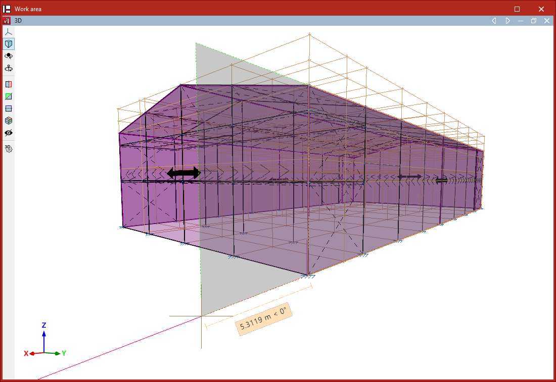
- Now, left-click to select a reference point for the displacement, then click the destination point to which you wish to move the selected reference point.
- Finally, right-click again to confirm.
The result is a surface load with modified geometry.
Assign
The "Assign" option allows you to enable or disable the assignment of surface loads to bars, meaning you can specify whether certain bars are to receive loads from panels or surface loads.
Select the bars to be enabled or disabled one by one with the left mouse button, or use a selection area. Then, right-click.
Disabled bars are displayed as dashed lines, while enabled bars are shown with solid lines. By default, all bars (except ties) are enabled.
If a bar is disabled, it cannot receive surface loads in any load case. This option does not apply to bars defined as ties, as ties cannot receive loads.