Geometry editing tools
The tools for editing the geometry of model elements in CYPE 3D are located in the “Tools” panel at the top of the interface, within the “Geometry” tab (under the “Structure” tab).

They are as follows:
- Move items
- Copy items
- Rotate elements in the xy plane
- Rotate elements about an axis defined by two points
- Rotate elements in the xy plane given three points
- Element symmetry in the xy plane
- Element symmetry with respect to a plane
- Search
- Assign reference
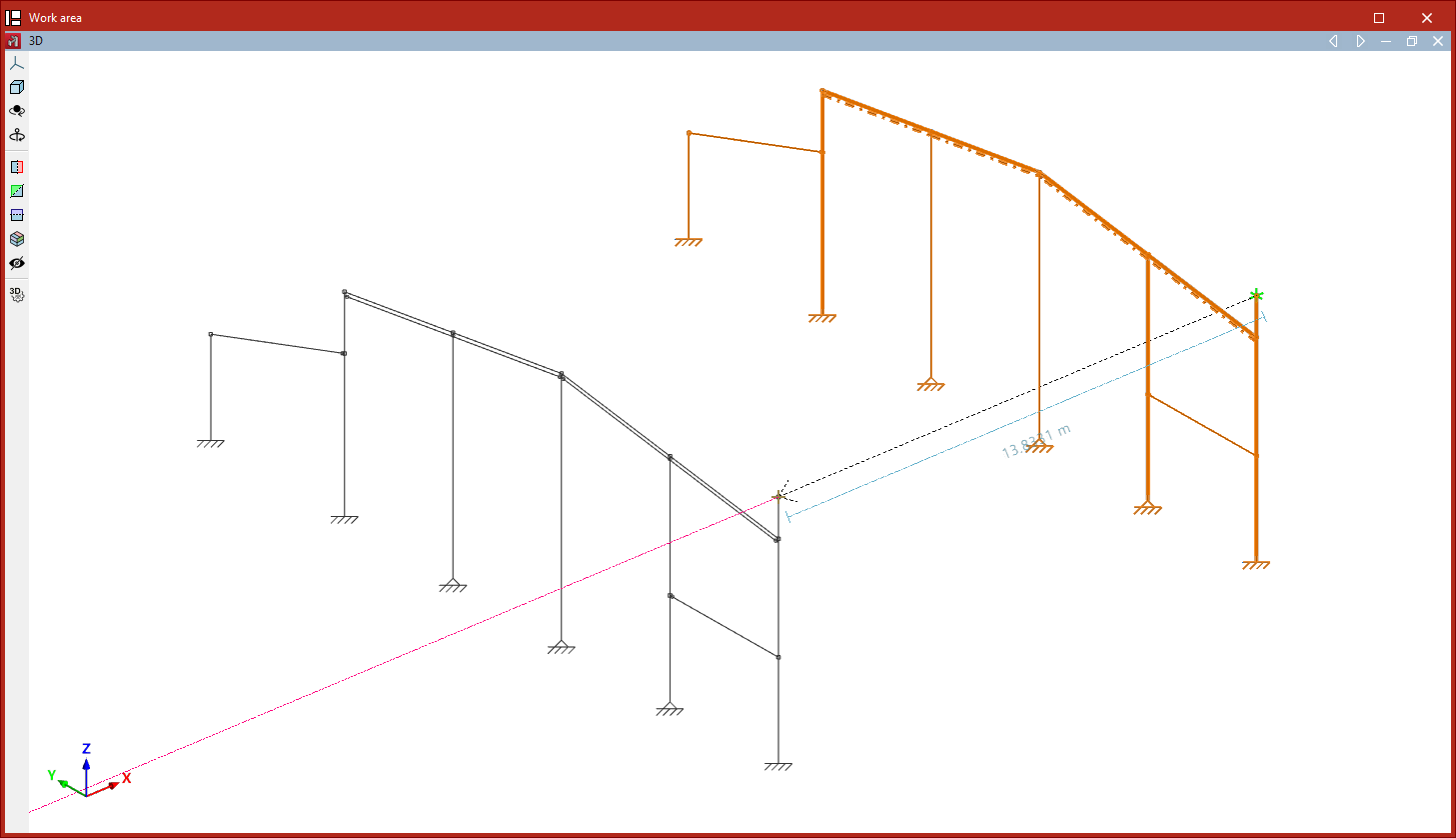
Move elements
The "Move elements" option allows you to move a selection of elements to a new position in the workspace:
- After clicking on the option, select the elements to be moved one by one using the left mouse button, or highlight a selection area.
- Then, click the right button to confirm your selection.
- Next, use the left mouse button to click on two points that define the start and end of the movement.
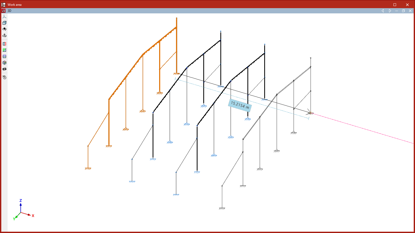
Copy elements
The "Copy elements" option allows you to copy a selection of elements to a new location:
- After clicking on the option, select the items to be copied one by one using the left mouse button, or highlight a selection area.
- Then, click the right button to confirm your selection.
- Next, left-click to select two points that define the start and end points of the copied elements’ movement.
Rotate elements in the xy plane
The "Rotate elements in the xy plane" option allows you to rotate a selection of elements around the global Z-axis:
- After clicking on the option, use the left mouse button to select the items you wish to rotate.
- Click the right mouse button to confirm your selection.
- Next, left-click on the rotation point.
- Next, using the left mouse button again, select two points that define the sides of the rotation angle.
- Finally, the "Rotation angle" value displayed by the program must be confirmed by clicking on the green tick.
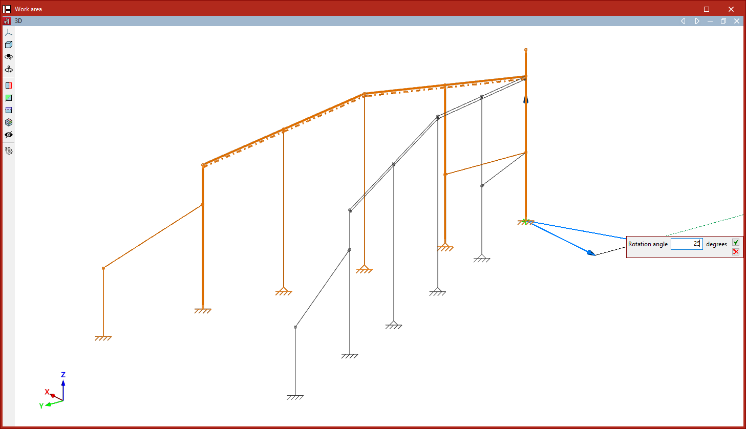
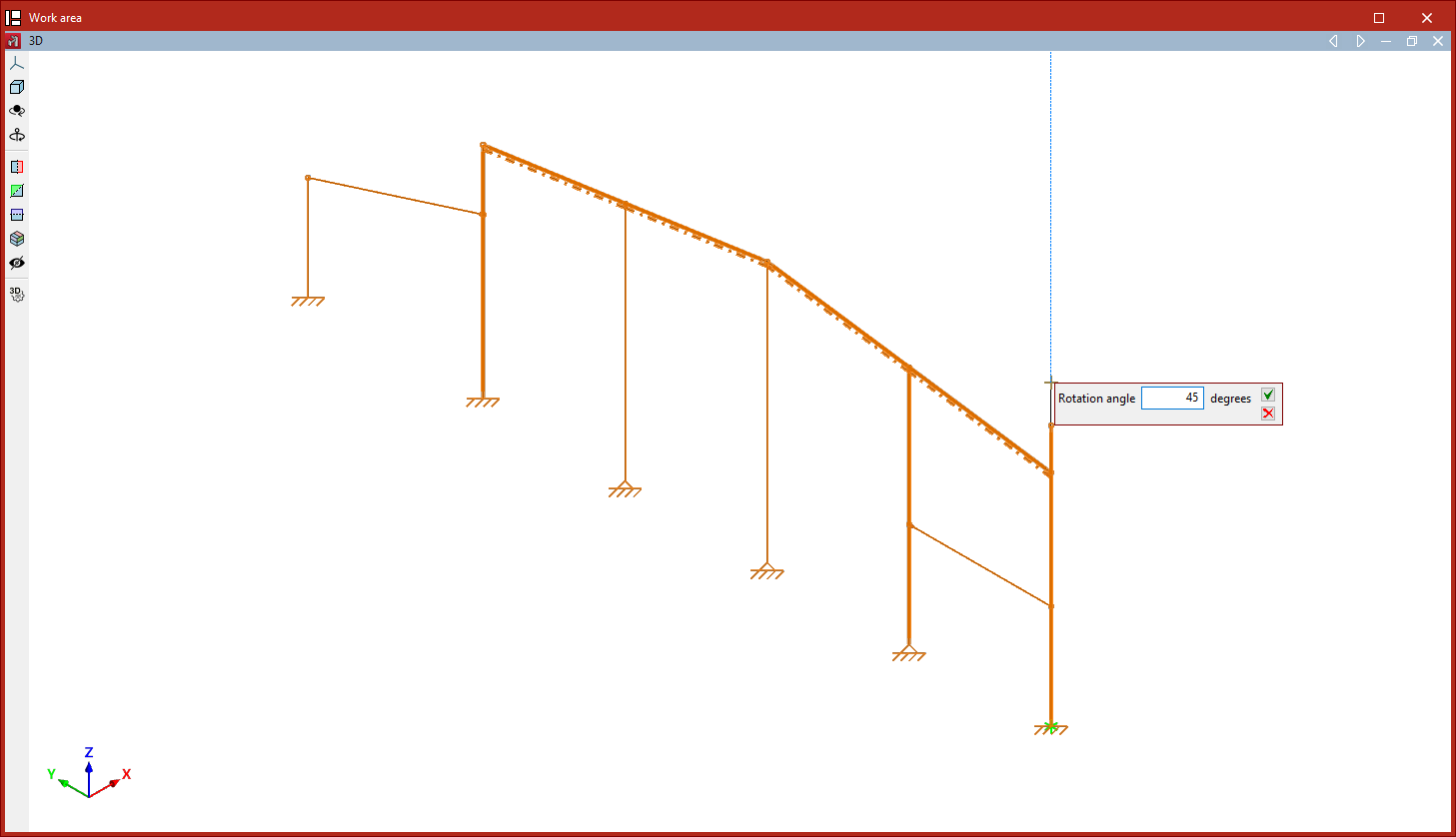
Rotate elements about an axis defined by two points
The "Rotate elements about an axis defined by two points" option allows you to rotate a selection of elements around any axis defined by the user:
- After clicking on the option, select the items to be rotated using the left mouse button.
- Click the right mouse button to confirm your selection.
- Now, use the left mouse button to select the two points that define the axis of rotation.
- Finally, enter the "Rotation angle" around the specified axis and click on the green tick to confirm the operation.
| Note: |
|---|
| If any of the rotation operations mentioned above are performed in a 2D view, the rotation takes place in the plan view. To do this, select the elements using the left mouse button and confirm the selection with the right mouse button. Then, simply click the left mouse button to select two points that define the angle of rotation. |
Rotate elements in the xy plane given three points
The "Rotate elements in the xy plane given three points" command is used to rotate a selection of elements around the global Z-axis, relative to the origin specified by the user and by an angle defined by any three points:
- After clicking on the option, select the items to be rotated using the left mouse button.
- Click the right button to confirm your selection.
- Next, left-click to select the rotation point.
- Next, click on any three points with the left mouse button to define the magnitude of the rotation, thereby defining the vertex and the two sides of the axis of rotation.
- Finally, confirm the "Rotation angle" by clicking on the green tick.
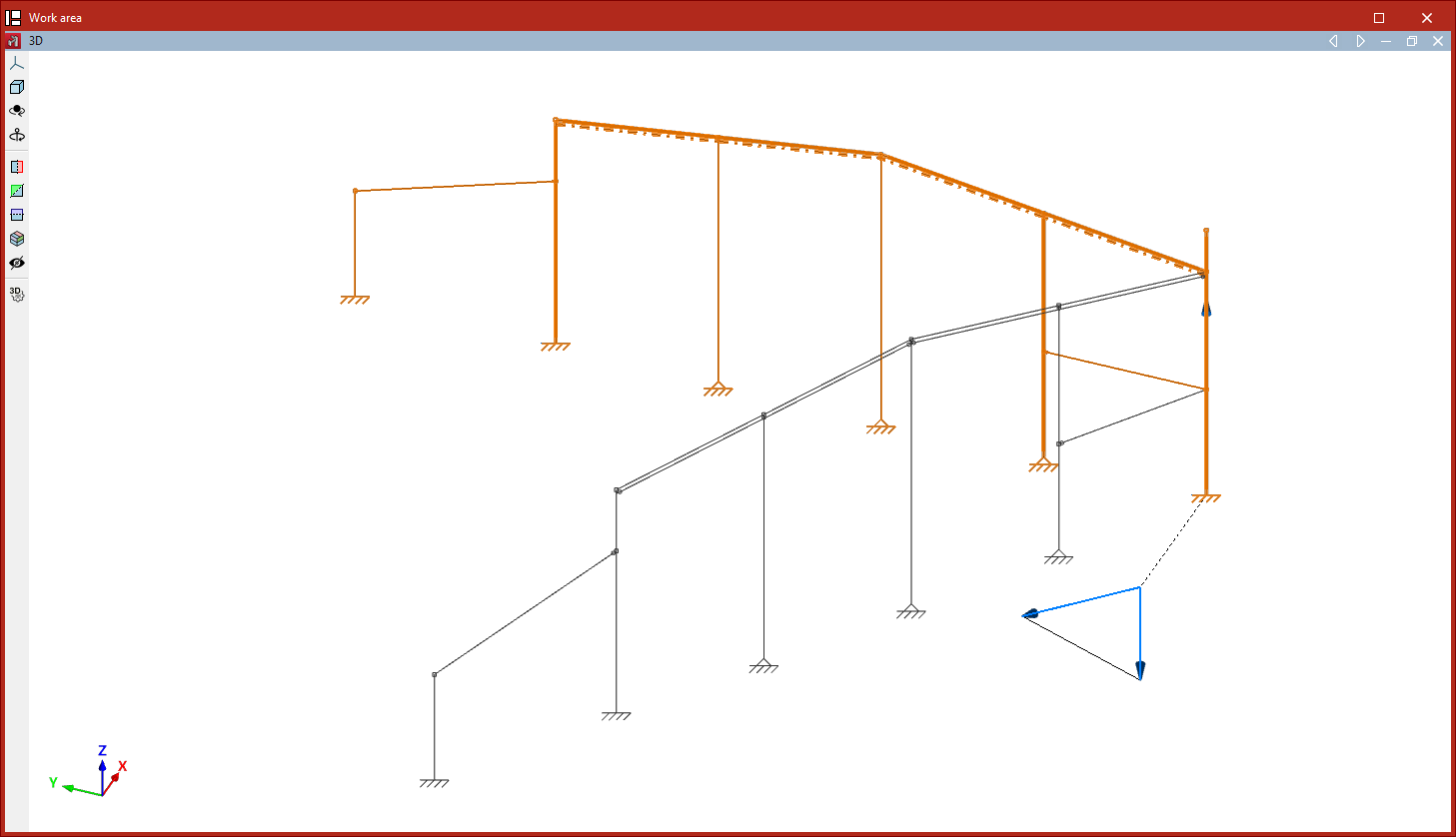
Element symmetry in the xy plane
The "Element symmetry in the xy plane" option allows you to create a mirror image of a selection of elements with respect to the plane defined by a user-defined vector and the global Z-axis:
- After clicking on the option, use the left mouse button to select the elements you wish to copy symmetrically.
- Click the right mouse button to confirm your selection.
- Next, use the left mouse button to select the two points that define the centre of symmetry and the direction of the vector in the global XY plane.
If the operation is performed in a 2D view, the symmetry is applied with respect to the line defined by the vector:
- To do this, select the items using the left mouse button and then right-click.
- Next, click the left mouse button to select two points that form the axis of symmetry.
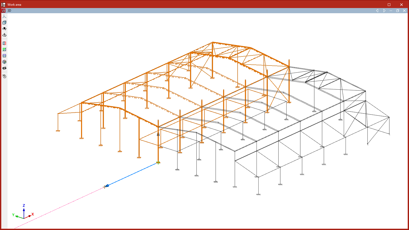
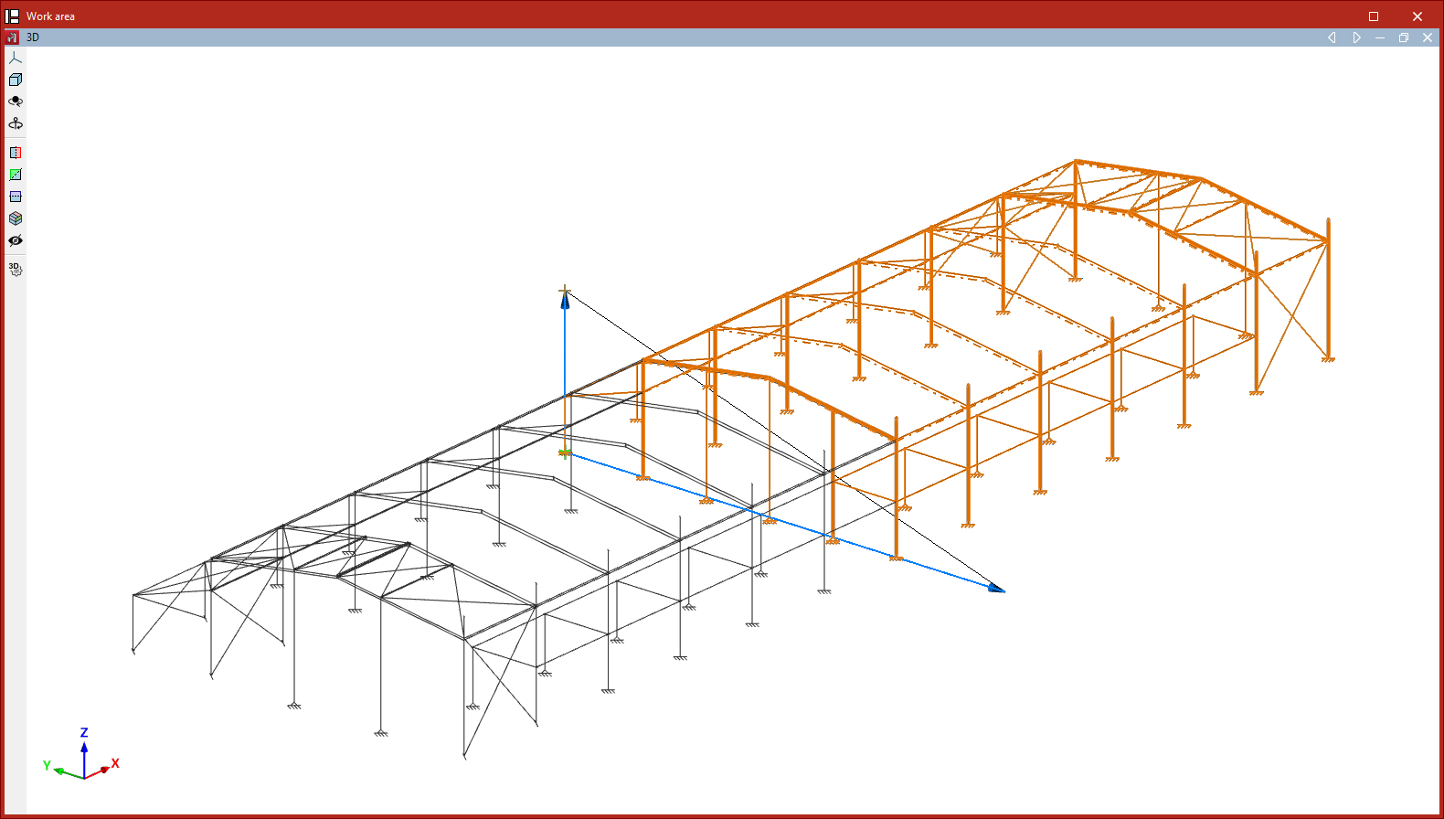
Element symmetry with respect to a plane
The "Element symmetry with respect to a plane" option allows you to create a mirror image of a selection of elements about a plane defined by three points:
- After clicking on the option, use the left mouse button to select the elements to be mirrored.
- Click the right button to confirm your selection.
- Next, left-click on the three points that define the symmetry plane.
As in the previous case, if this operation is performed in a 2D view, the symmetry is applied about a line defined by two points.
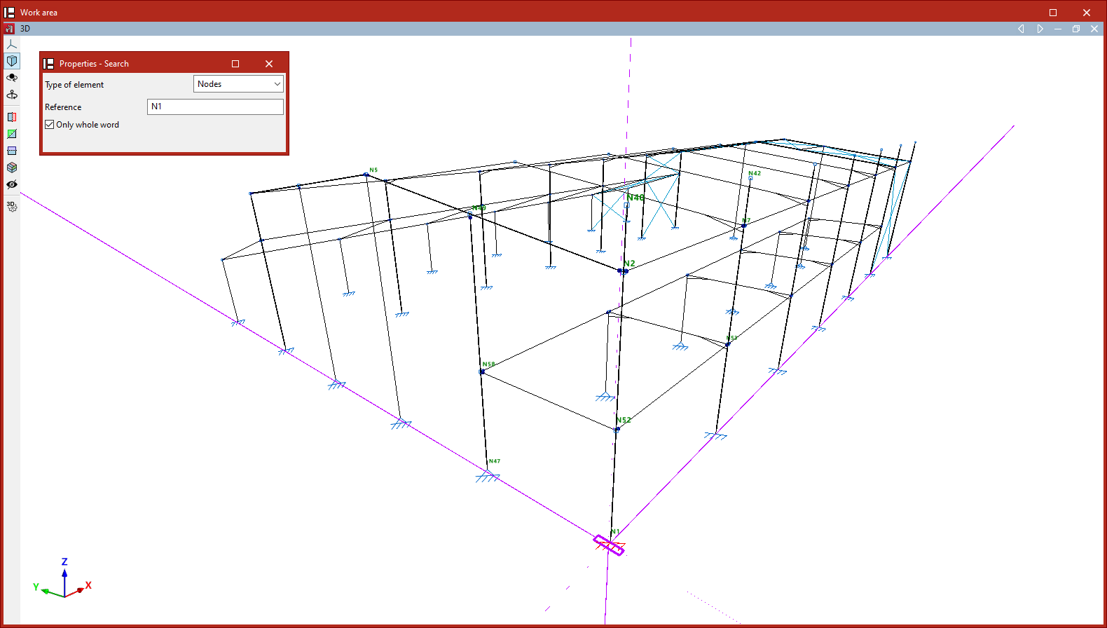
Search
The "Search" option allows you to search for elements of the selected "Element type" ("Nodes", "Bars", "Parts", "Deflection groups" or"Connections") by entering their "Reference".
If you wish to search for items by entering the full text of the reference, tick the "Only whole word" box. If you untick it, you can search by entering just part of the text.
The program will highlight in red any elements whose reference matches the text entered and will frame them with magenta lines in the model view.
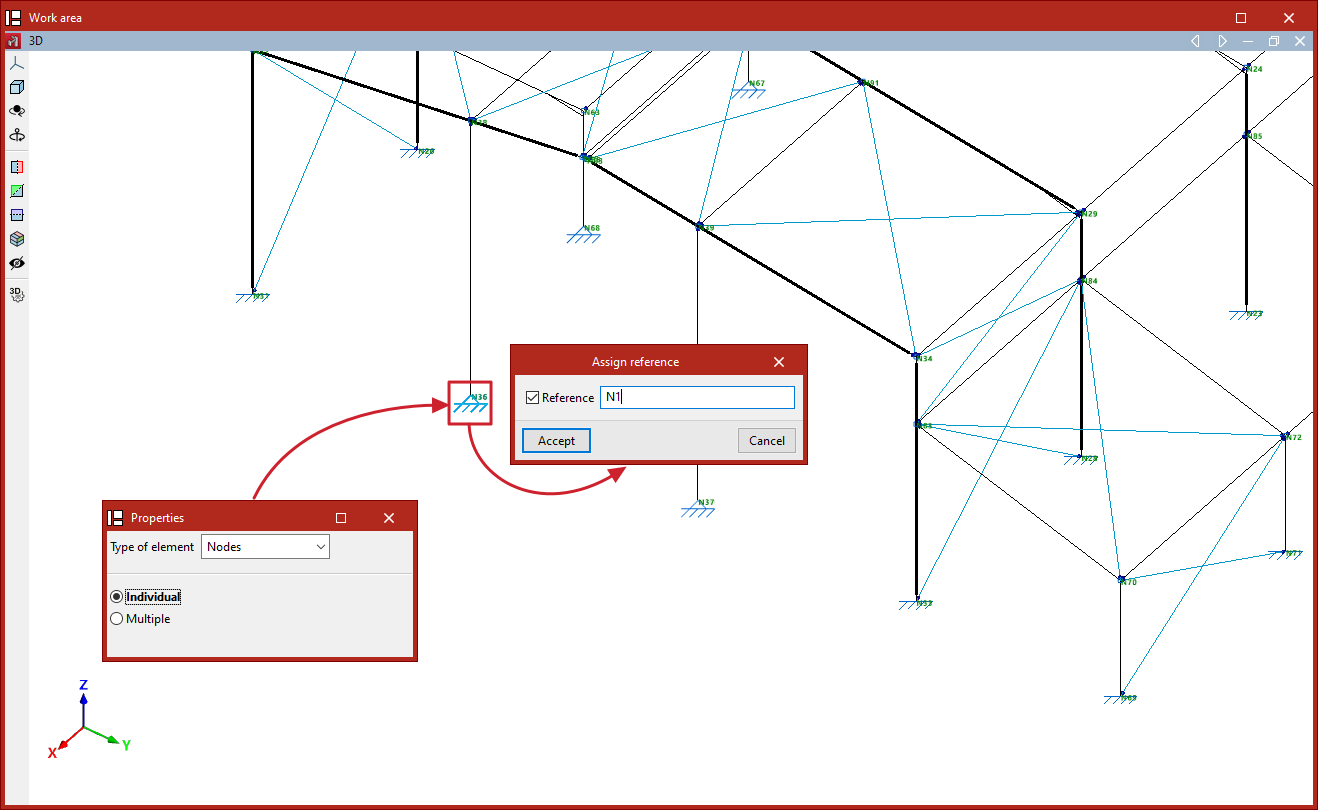
Assign reference
The program automatically generates element references based on the options selected in the "Numbering" section of the "Project" tab. To edit element references at a later stage and assign them the references of your choice, use the "Assign reference" option in the "Tools" section of the "Geometry" tab.
When you click on this option, you must first select the "Element type" from the drop-down menu (whether "Nodes", "Bars", "Parts", "Arrow groups" or "Beams") and specify whether the assignment will be single or multiple:
- Single
Allows you to assign the reference to a single element. To do this, after selecting the element, enter the desired "Reference" in the pop-up dialogue box. - Multiple
Allows you to assign a reference number to a selection of elements. To do this, after selecting the elements, enter a "Starting reference". The program will assign a sequential reference number to each element in the selection, starting from the starting reference.
If repeated references are defined, a warning will appear when printing reports or drawings, as well as when "Show issues" is selected.