Carpentry editor
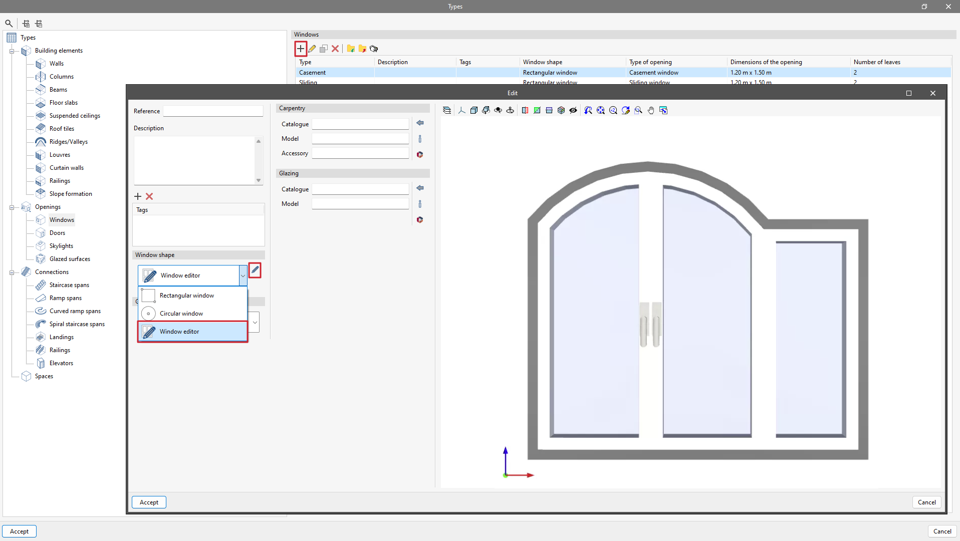
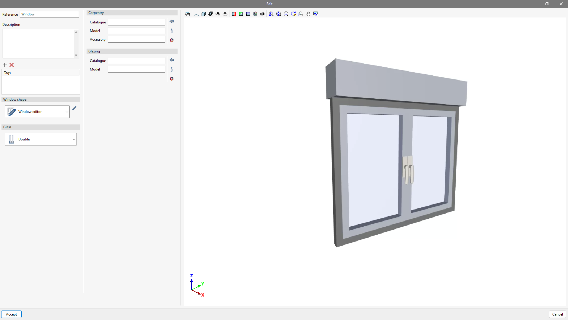
CYPE Architecture allows windows, doors and skylights to be drawn freely. From “Types”, when creating a new type, such as for windows, the "Window editor" option can be selected in the "Window shape" section.
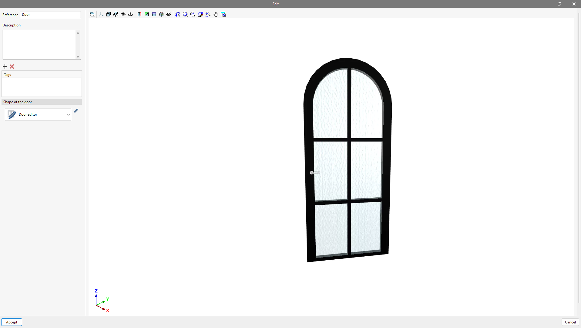
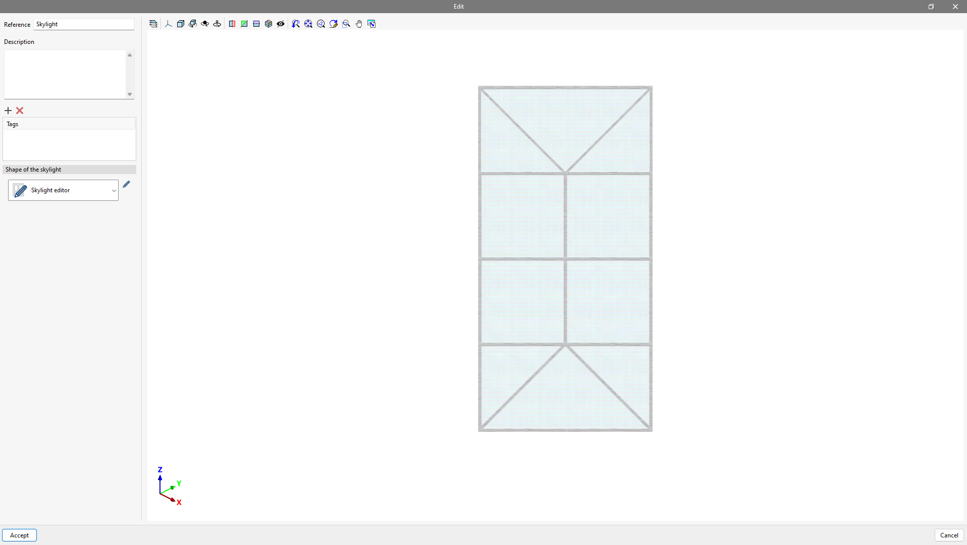
Carpentry editing (windows, doors and skylights) is accessed by selecting the "Edit windows" option in the drop-down menu and clicking on the pencil icon.
The pop-up window follows the same drawing logic used by CYPE Architecture with the sketch/architecture duality, to take advantage of the benefits offered by the sketch drawing when defining the carpentry. Therefore, the toolbar is divided into two groups: "Sketch" and "Carpentry".
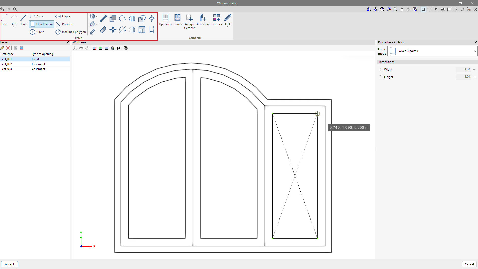
Sketch
The "Sketch" group is divided into two sections.
Here, users can find all the necessary tools for drawing the sketch design, such as lines, arcs, circles, rectangles, ellipses, polygons and inscribed polygons. Also, references can be created by selecting the dashed line or dashed arc options. These tools are similar to those described in the "Sketch design tools" section.
On the other hand, there are all the tools related to editing the sketch elements, such as editing, moving, rotating, offsetting, etc. It is also possible to group and ungroup sketch elements, create a colour library, assign colours to each sketch element and measure them. All these editing tools are similar to those found in the "Sketch" tab of CYPE Architecture.
Carpentry
The "Carpentry" group allows users to enter the elements specific to each type (door, window or skylight), always based on the sketch drawing.
With the "Openings" feature, you define the perimeter of the carpentry by selecting the drawn sketch lines. The carpentry opening is shown in red in the "Work area".
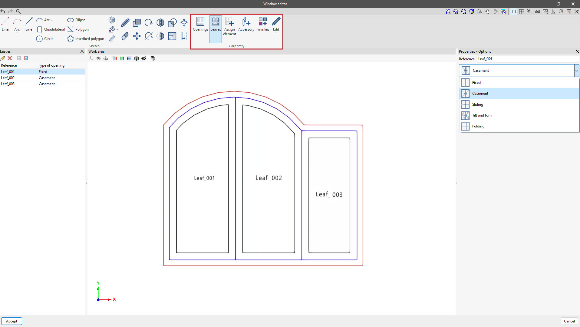
Using the "Leaves" option, it is possible to choose between different opening options: fixed, casement, sliding, tilt and turn and fold. Once the opening type has been selected, the leaves are assigned by selecting the sketch lines, making sure that closed contours are selected. The assigned leaves are shown in blue on the model.
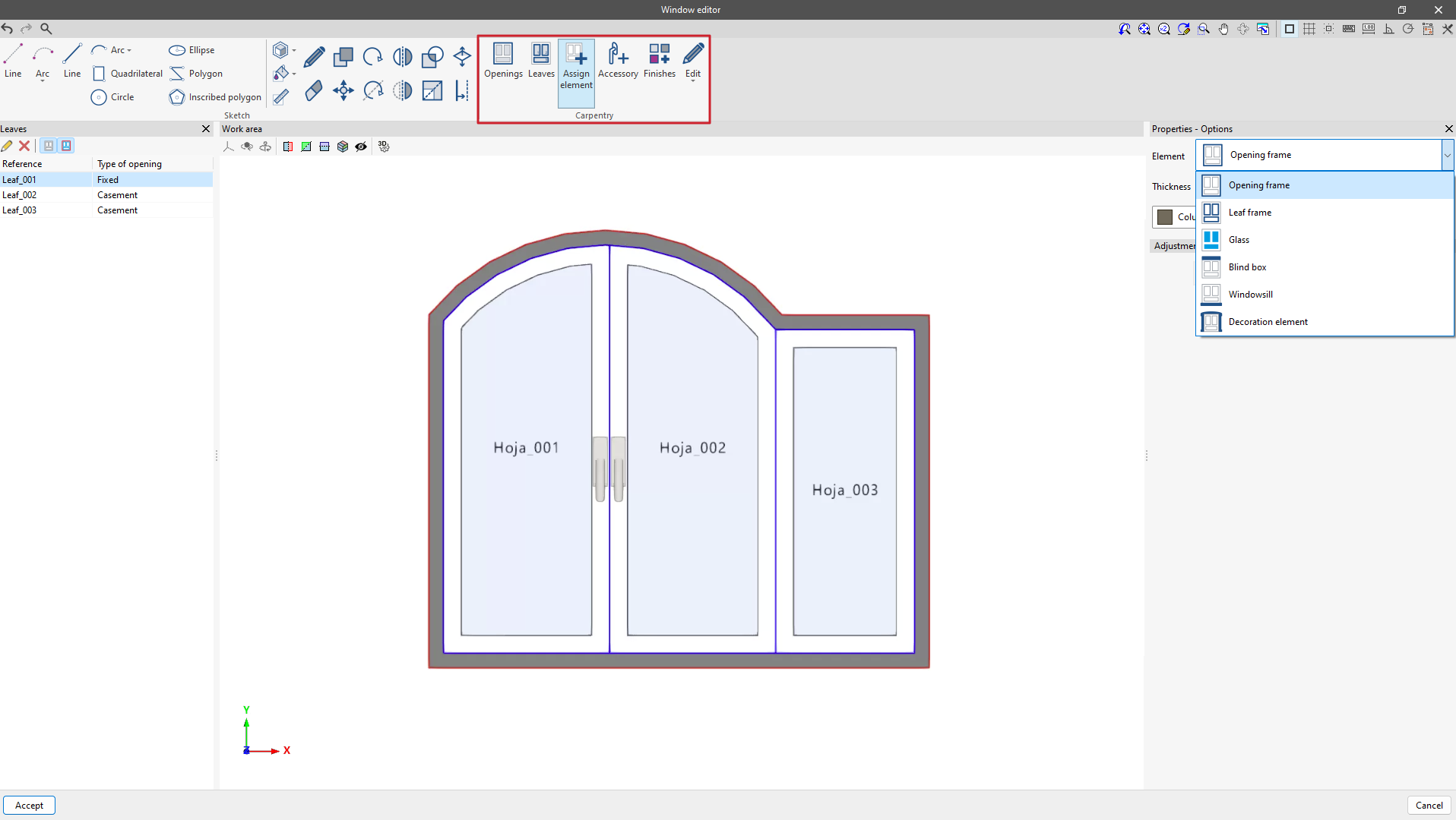
Once the openings and leaves have been assigned, the next step is the "Assign elements" option, with which the functions of each sketch surface can be defined, such as opening frame, leaf frame, glass, opaque surface, shutter box, window sill and decorative element.
Accessories such as window handles or door knobs can also be inserted from "Accessory".
Each assigned element has a colour or texture associated with it. From the "Finishes" option, users can access the project library to create or edit new finishes.
All these assigned elements can be deleted, duplicated, edited and moved from the "Edit" option. These tools should not be confused with the editing tools in the "Sketch" group, as the tools in the "Sketch" group are not used to edit the elements in the "Carpentry" group and vice versa.
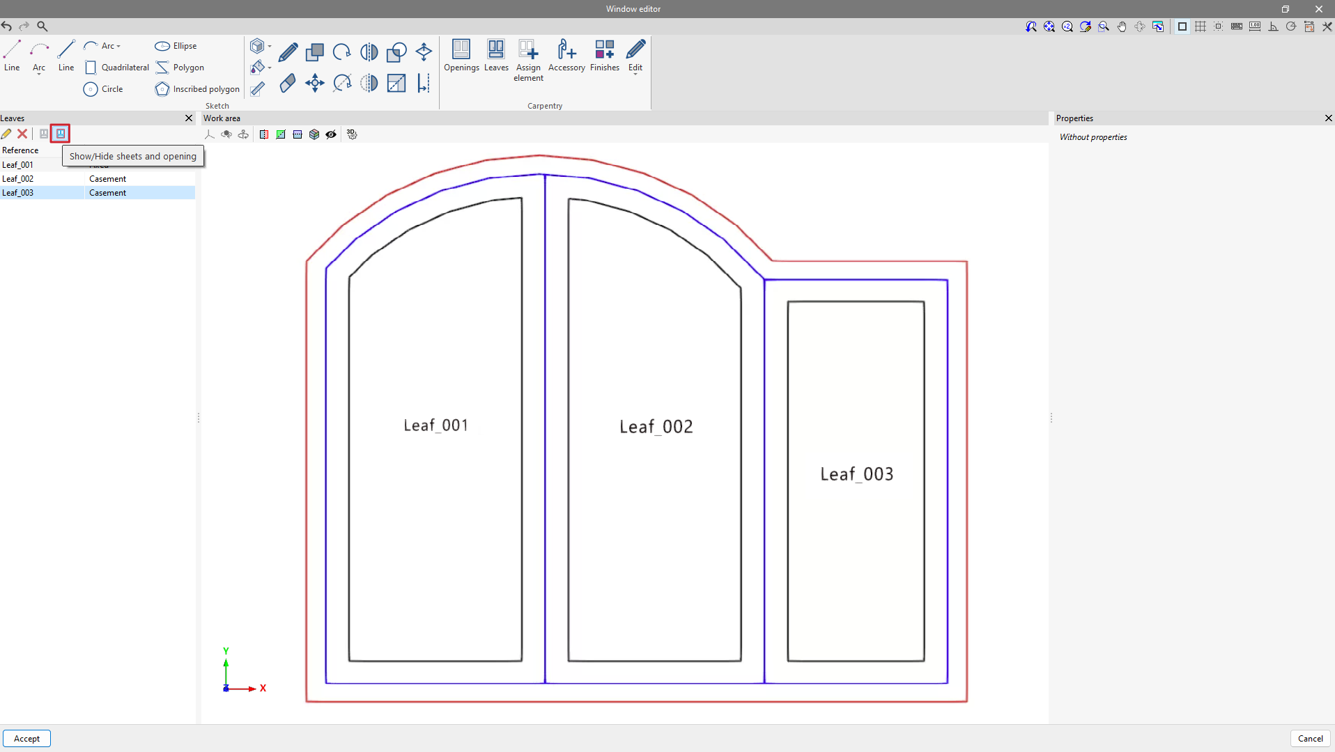
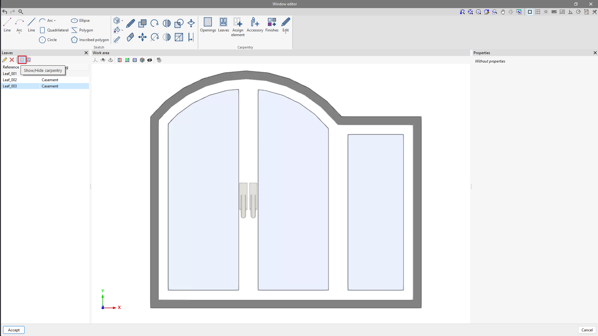
| Note: |
|---|
| From the toolbar of the "Leaves" section, users can control the visibility of the elements in the openings and leaves using the "Show/Hide leaves and openings" option, as well as control the elements assigned to them (frame, glass, etc.) using "Show/Hide carpentry". |