


Automatic generation from DXF/DWG files
The "Automatic generation from DXF/DWG" option is used to automatically generate the geometry of the building’s walls and partitions, floor slabs, doors and windows, based on information extracted from a DXF or DWG file.
This feature is available in the following programs:
- CYPE Architecture (when creating a new project)
- IFC Builder (when creating a new project using the "Import CAD/BIM" option)
- CYPETHERM (using the "Import CAD/BIM" option in the "3D Model" tab)
- CYPEFIRE FDS (using the "Import CAD/BIM" option in the "3D Model" tab)
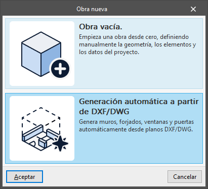
When this option is selected, the program launches the “Automatically generated from DXF/DWG” wizard, which guides the user through the data definition process in a series of stages. These stages are displayed in the navigation pane on the left-hand side and can be accessed using the “Next” and “Previous” buttons.
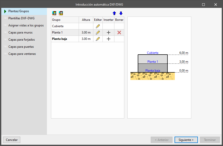
Floors/Groups
In the first stage of the wizard, you must create the floors and/or groups of floors for the model.
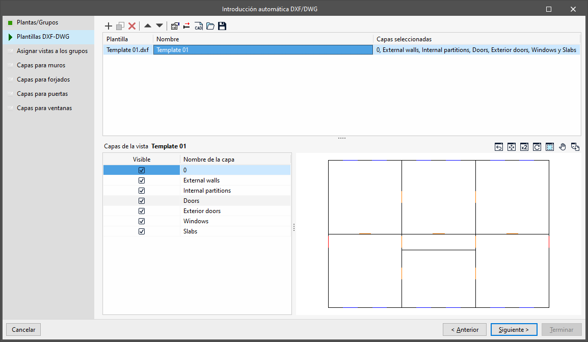
DXF/DWG templates
In the next step, you must add the DXF and/or DWG files you wish to use for automatic generation.
The program offers the same options here as the "Template View Management" window, which can be accessed from the main interface.
You can add multiple DXF and/or DWG files.
The data in the selected files must be organised into layers for subsequent processing by the program and must be drawn at full scale.
| Note: |
|---|
| To minimise geometric issues, wall data may be represented by lines situated on their centreline or reference line, with a single line for each wall section, whilst floor slabs may be represented by the polygons of their perimeter or outline. Doors and windows must be represented by a line with its centre positioned at the centre of the door or window. The structure and layout of these lines should follow the modelling recommendations for each program in order to minimise the subsequent work involved in adjusting the model geometry, paying particular attention to the intersections between elements. You can download a sample DXF file with these characteristics via this link. |
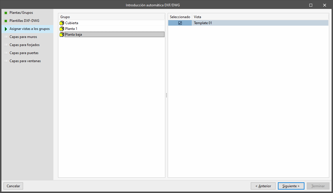
Assign views to groups
At this stage, you must select the DXF and/or DWG files to be used for the automatic generation of building elements in each of the floor plans created.
To do this, select each "Group" of floors on the left and tick the "Selected" box on the right to specify the "View" to be used.
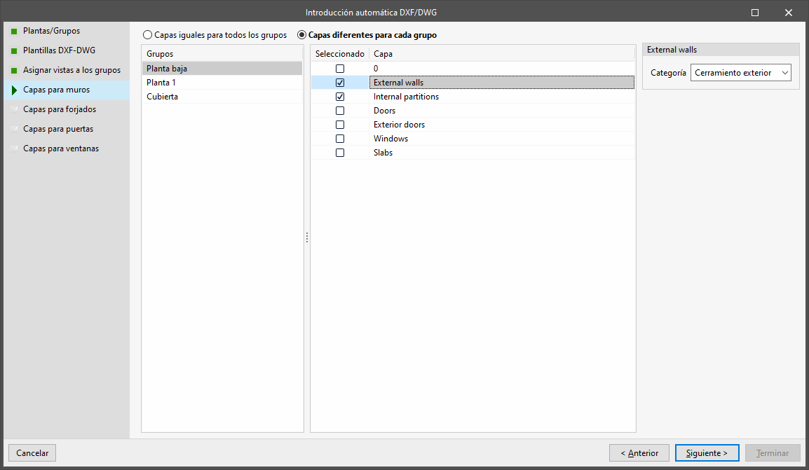
Wall layers
In this phase, you specify the layers in the DXF file that you wish to use for the automatic generation of walls and partitions in each floor group.
To do this, you must first select whether to use "The same layers for all floor groups" or "Different layers for each group". In the latter case, you will need to assign layers to each of the floor "Groups" selected in the left-hand column.
Next, tick the "Selected" box to specify the "Layer" or layers you wish to use in the wall generation process. On the right, select the "Type" of wall or partition to be generated using the information from each layer (either "Exterior Wall", "Interior Partition", "Basement Wall" or "Retaining Wall").
| Note: |
|---|
| The DXF or DWG file should ideally have a separate layer for each type of wall. |
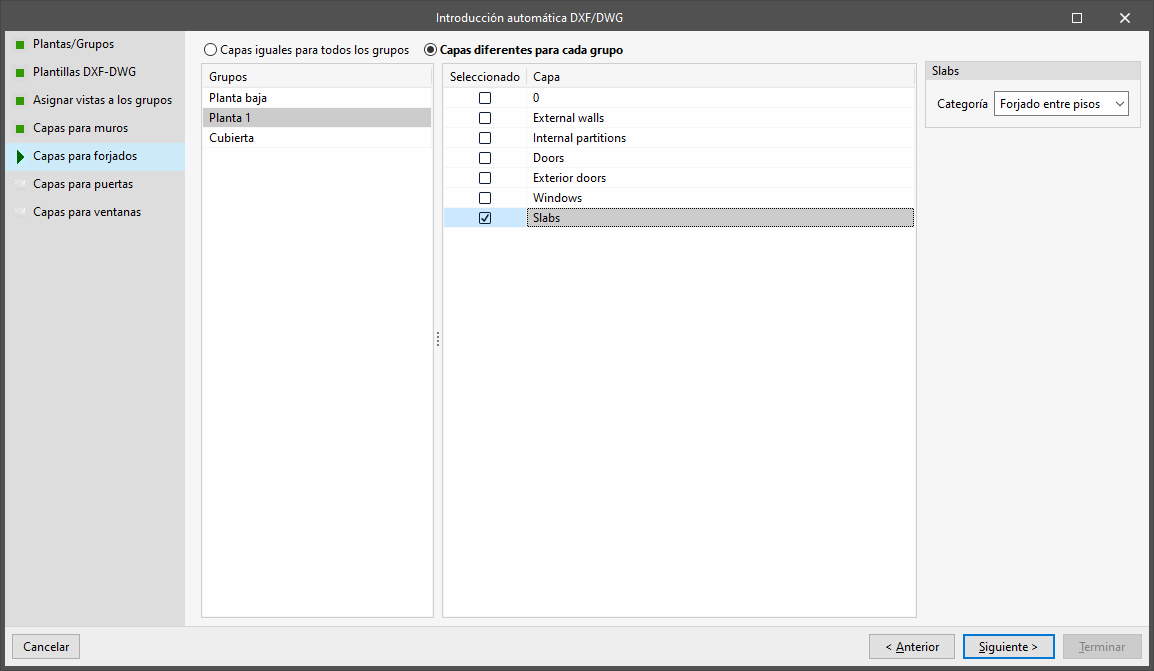
Floor slab layer
In this phase, you specify the layers in the DXF file that you wish to use for the automatic generation of floor slabs in each group of floors.
To do this, you must first select whether to use "The same layers for all floor groups" or "Different layers for each group". In the latter case, you will need to assign layers to each of the floor "Groups" selected in the left-hand column.
Next, tick the "Selected" box to indicate the "Layer" or layers you wish to use in the floor slab generation process. On the right, select the "Type" of wall or partition to be generated using the information from each layer (either "Floor slab", "Intermediate floor slab" or "Roof").
| Note: |
|---|
| The DXF or DWG file should ideally have a separate layer for each type of floor slab. |
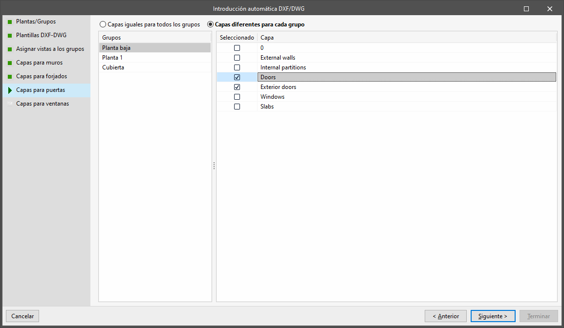
Door layer
In this phase, you specify the layers of the DXF file that you wish to use for the automatic generation of doors in each floor group.
To do this, you must first select whether to use "The same layers for all floor groups" or "Different layers for each group". In the latter case, you will need to assign layers to each of the floor "Groups" selected in the left-hand column.
Next, tick the "Selected" box to specify the "Layer" or layers you wish to use in the door generation process.
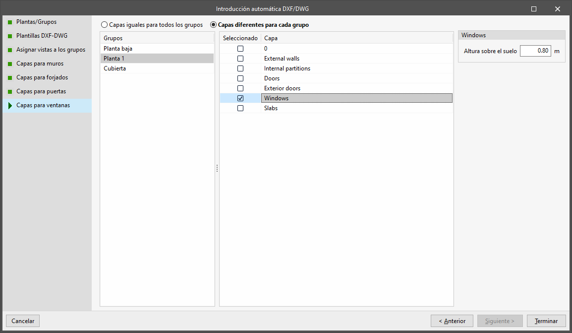
Window layer
In this phase, you specify the layers in the DXF file that you wish to use for the automatic generation of windows in each group of floors.
To do this, you must first select whether to use "The same layers for all floor groups" or "Different layers for each group". In the latter case, you will need to assign layers to each of the floor "Groups" selected in the left-hand column.
Next, tick the "Selected" box to specify the "Layer" or layers to be used in the door generation process. You must specify the height parameter relative to the floor for each selected layer.
Import results
Once you have completed the configuration of the various steps in the wizard, click "Finish".
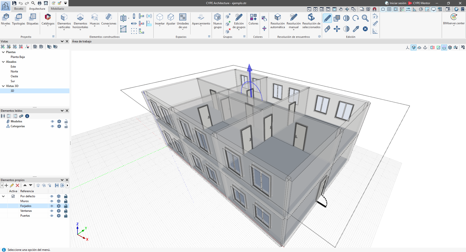
The program will then open the main interface, generating the geometry of the walls, floor slabs, doors and/or windows, and allow you to continue working.
Following the automatic generation of data from a DXF/DWG file, it is advisable to check the generated geometry and make any necessary adjustments to ensure it complies with the program’s modelling guidelines. Subsequently, the imported elements must be edited and their type configured. You must also enter sloping roofs, spaces and, where applicable, services and/or other building elements, as these are not read during the automatic import process from DXF/DWG files.
Reading DXF/DWG files and importing their data via this wizard is a one-way process, and it is not possible to update the data if the information in the DXF/DWG file changes. In that case, you could perform a new DXF/DWG import into a new project.