

Analysis and code checking of connections
Once the connection has been modelled, the analysis and checking can be carried out. The "Analysis" tab has the following options for this purpose:
Generate from the BIM model
This option will be available when the job has been created from a BIM model with forces. The load cases and loads of the sections involved in the connection can be generated.
To do this, the load combinations to be read can be filtered. Not all load combinations have significant values, so it may be advisable to filter the number of combinations to be imported. By default, a filter is shown for each of the 6 forces. The combinations in which the force exceeds the maximum value by a certain percentage, both positive and negative, will be read for each force. Furthermore, a minimum value can be set to determine whether the combinations should be read.
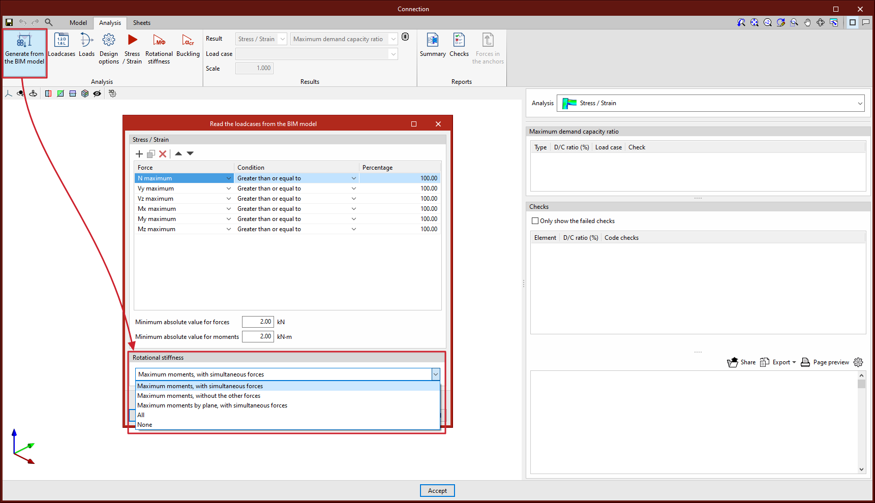
With this option, loads can also be imported for the rotational stiffness analysis. In addition to the loads, the elastic lengths of the bars of the structural model are also imported; these lengths are necessary for the correct classification of the connection. There are five options for importing load cases according to forces:
- Maximum moments, with simultaneous forces
Imports the load cases with the largest moments "My" or "Mz", with a positive or negative sign, in addition to the other simultaneous forces. - Maximum moments, without the other forces
Only imports the "My" and "Mz" values from load cases with maximum moments. - Maximum moments by plane, with simultaneous forces
Imports load cases with maximum moments and their simultaneous forces per plane i.e. creates load cases with forces per plane (XY and XZ). - All
Imports all load cases. - None
No load cases are imported.
Loadcases
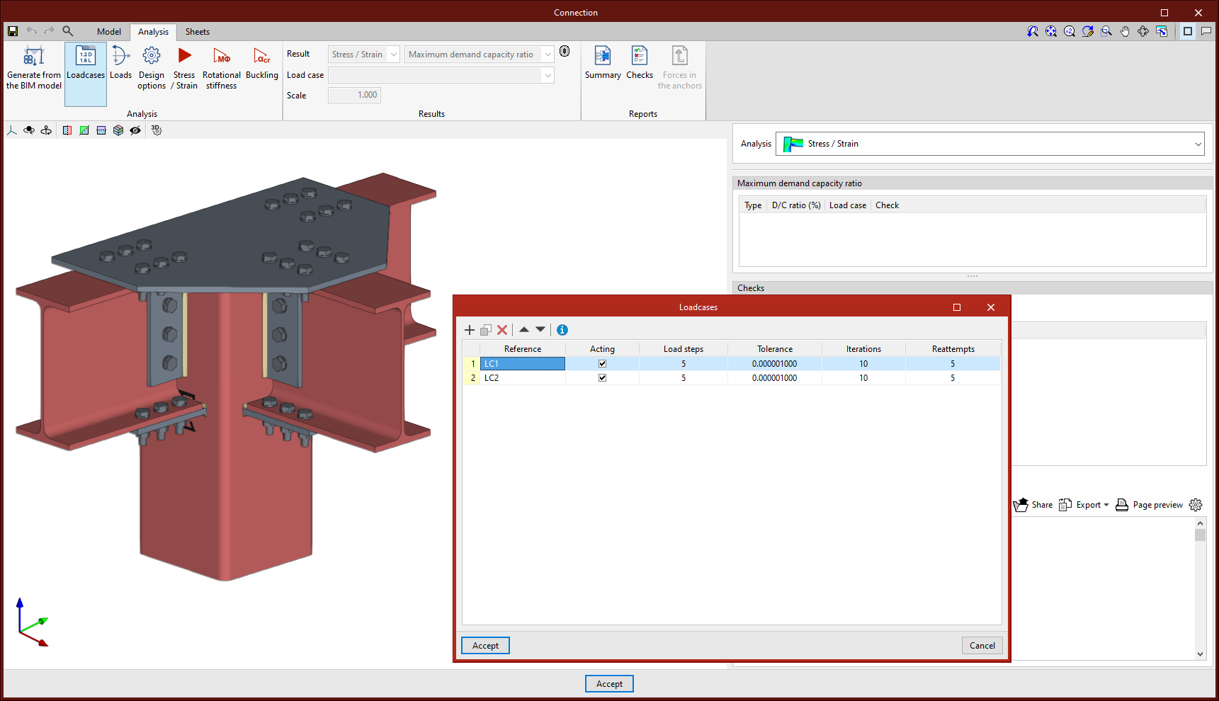
This option can be used for defining the load cases to be considered in the connection analysis. These load cases can be generated from the BIM model or configured manually by the user. The following parameters are defined for each load case:
- Number of load steps.
- Allowable tolerance to consider the convergence has been reached.
- Maximum number of iterations in each load step.
- Maximum number of reattempts.
Loads
This tool opens the "Loads" dialogue box, where the loads acting on each section for each load case are defined.
In the connection analysis model, one of the bars is set as the load-bearing element, unless a baseplate has been defined. The remaining bars are connected to this element, where the loads are applied.
Each non-load-bearing bar includes the "Design model" option, which selects different load and restraint configurations, best suited to various structural situations. Users can choose from the following options:
- N - Vy - Vz - Mx - My - Mz
This is the default model. The end of the bar has no external links, so that the six forces can be defined. - N - Vy - Mz
This model defines loads in the XY drawing. The end of the bar is constrained for displacement in the z-axis and rotation in the y-axis. - N - Vz - My
This model defines loads in the XZ-plane. The bar end is constrained for displacement in the y-axis and rotation in the z-axis. - N - Vy - Vz
In this model, the end of the bar is constrained for rotation and does not allow moments to be entered.
In the central part of the dialogue box, there are two tabs for defining load tables, per load case. Tables can be copied and pasted directly from a spreadsheet.
In the "Stress / Strain, Buckling" tab, in addition to the loads, it is possible to define the position of the force application point for each section. This distance will also be read in the BIM model, provided that the structure has been designed considering the finite dimension of the nodes.
The bars from which the rotational stiffness of the connection is to be analysed can also be selected. The "Rotational stiffness" tab asks for a report of loads, the lengths of the elastic bar in the structural model (used to establish the limit stiffnesses of rigid or pinned connections) and the kb factor.
The "Edit forces" tool, common to both tabs, is used to define the forces applied to each bar according to its mechanical properties. This feature makes it easier to design connections with a higher resistance than that of the connected bars, a common requirement in different seismic design standards.
To improve the visualisation, in the 3D view of the dialogue box, the loads applied to each bar in the connection are graphically represented according to the selected load case.


Dissipation elements
The analysis of connections with dissipative elements can be carried out. These tools can be used to design connections for earthquake-resistant structures in which energy dissipation is foreseen through the formation of plastic hinges, either in one of the elements of the connection or in the bars linked to it.
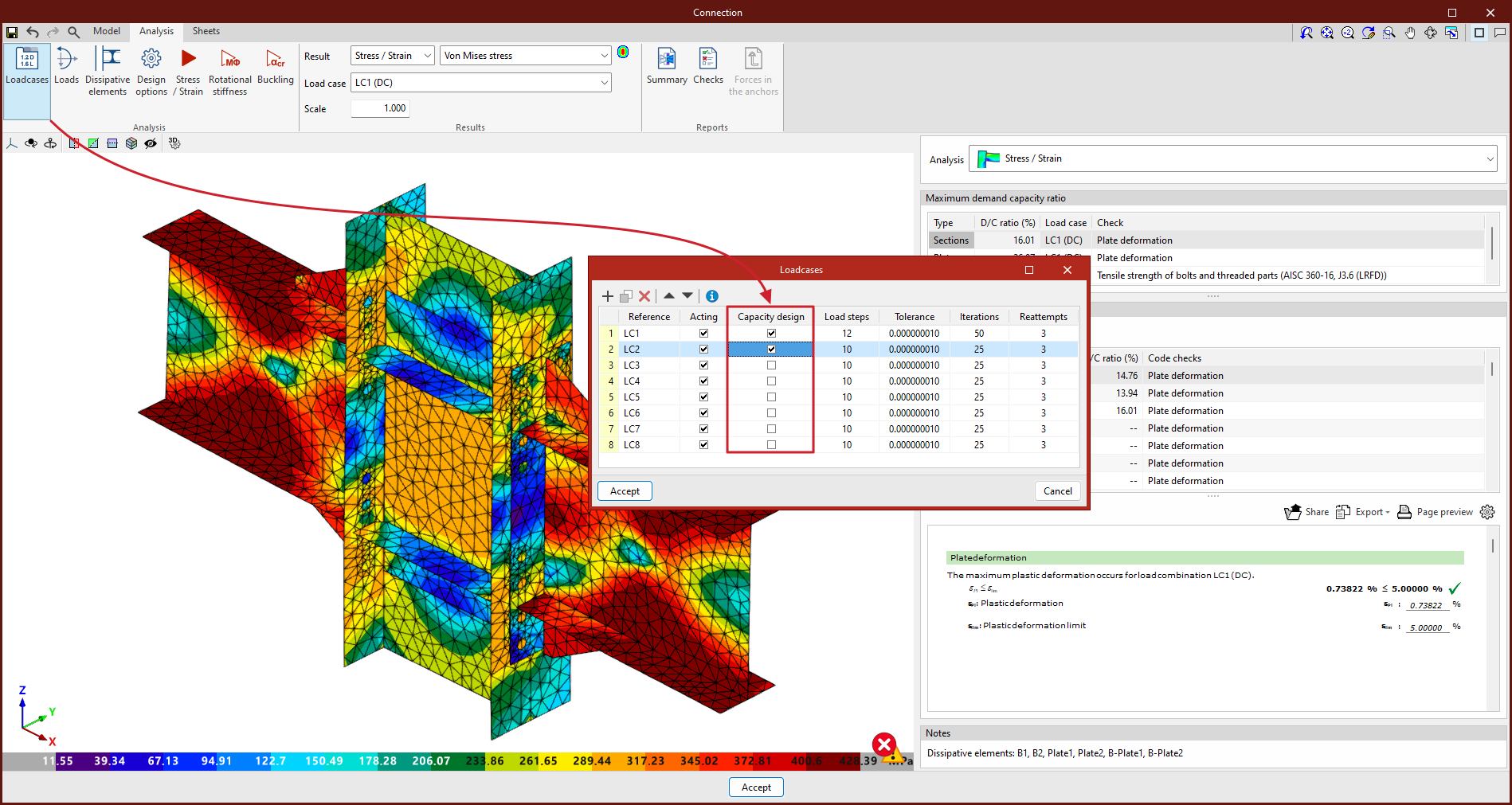
In the "Analysis" tab, a tool has been added to select the dissipative elements, offering users the option to choose between sections and plates. The material properties of the dissipative elements are transformed in the load cases marked as "Capacity design", considering the effects of material overstrength.
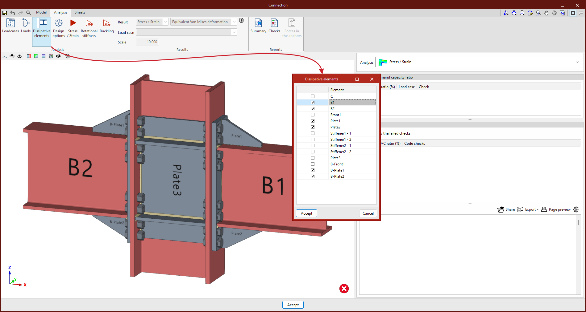
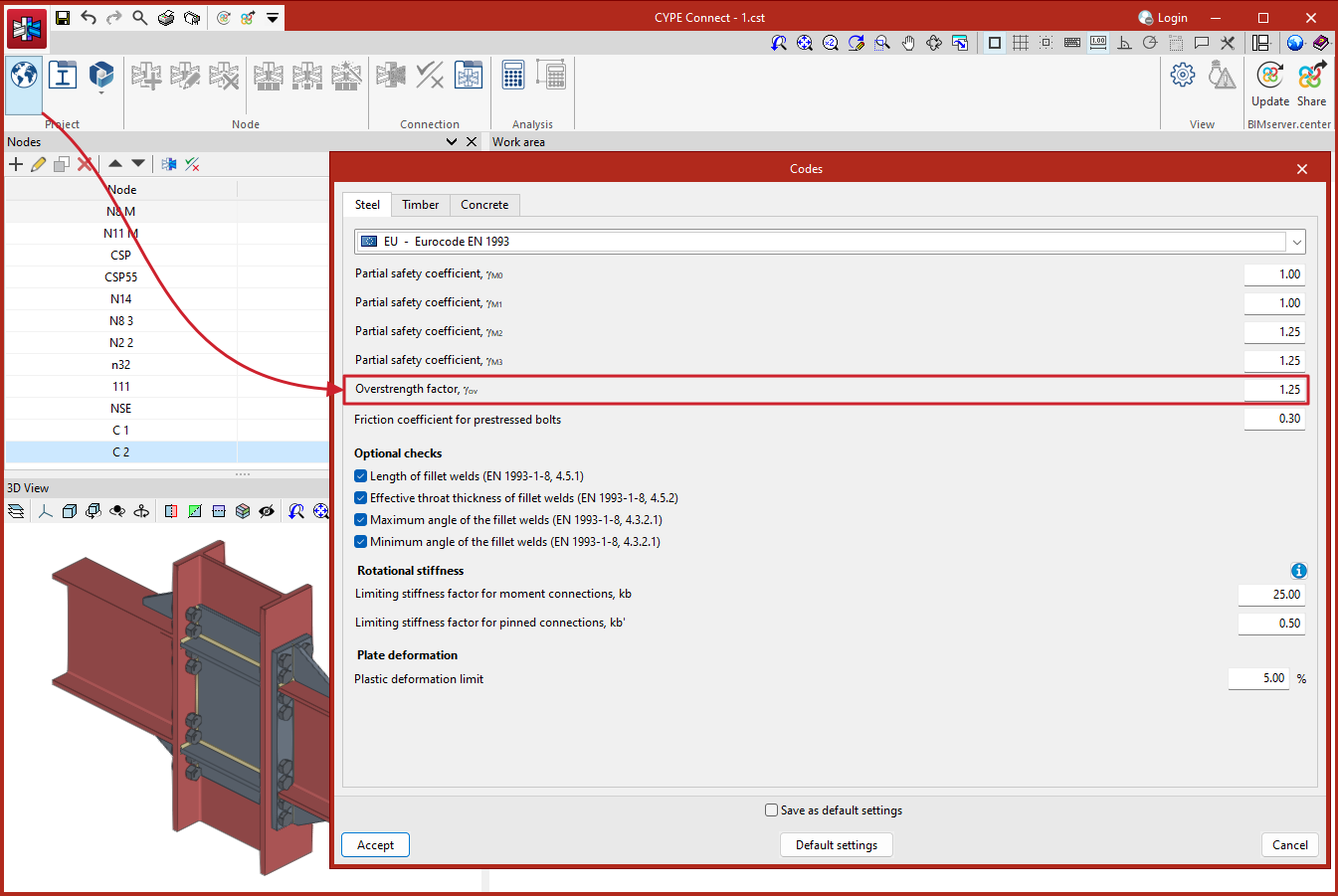
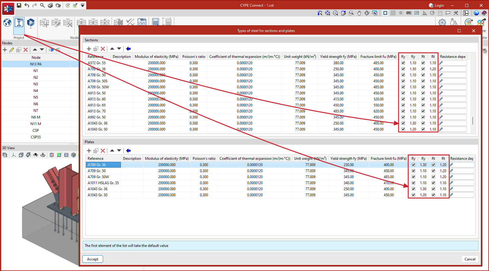
For Eurocodes and similar standards, the program will request the overstrength coefficient of the material, 𝛾ov, which amplifies both the yield strength and the ultimate strength of the dissipative elements. For American standards such as AISC360, NSR10, NTC-2023, among others, and other similar standards, the program will include in the material library the specific overstrength factors for each type of steel, Ry and Rt.
To analyse the connection for the over-resistance in dissipative elements, it is necessary to select not only the dissipative elements but also the "Capacity design" types of load cases in the list of load cases.
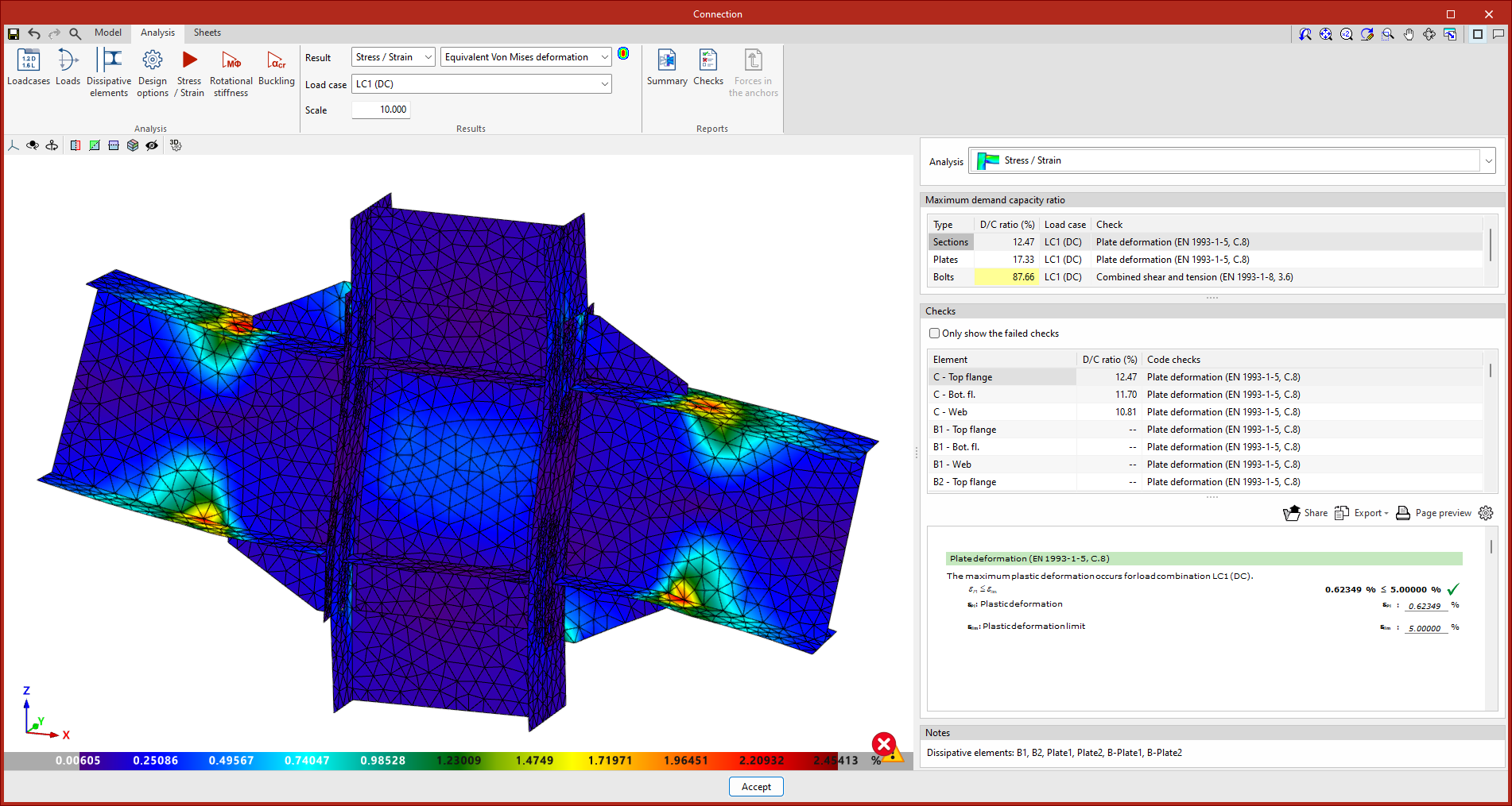
This new implementation allows users to design the connections so that the capacity of the connection is larger than that of the dissipative element while considering the over-resistance. In these cases, dissipative elements will experience large plastic deformations, which makes it difficult to converge the model, therefore, another relevant parameter in dissipative elements is the slope of the plastic span.
As detailed in the calculations manual, the constitutive law for plates and sections follows a bilinear model, where the slope of the plastic span is tan-¹(E/1000). For dissipative elements, in addition to incorporating the over-resistance coefficient as a multiplier of the yield stress, the slope of the plastic span is adjusted. In these elements, for a deformation of 5%, the stress will reach the elastic limit of the material, amplified by the over-resistance coefficient (𝛾ov or Ry, depending on the applied standard) and by the resistance reserve coefficient due to strain hardening, which is equal to 1.1. This slope, greater than tan-¹(E/1000), contributes to improve the convergence of the analysis.
Design options
Here, users can define the following:
- The maximum discretisation size of elements.
- The length to calculate the average weld stresses.
- The multi-process analysis method of the OpenSees© analysis engine.

| More information: |
|---|
| More information on analysis considerations can be found in the CYPE Connect calculation report. |