

Options for positioning bolts and anchors
StruBIM Steel and CYPE Connect offer various options for placing bolts and anchors. These options are available when using the "Bolt" or "Anchors" operations, located in the "Operations" group of the "Model" tab in the editing window for each connection. The available options are as follows.
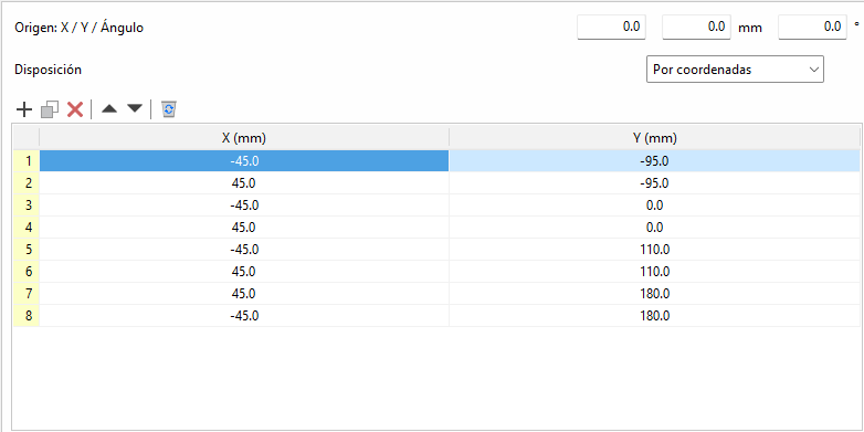
By coordinates
Elements can be placed by directly indicating their X and Y coordinates in a table. This is the ideal option for cases where a more precise location of each element is required.
The origin of the local reference system for openings, bolts and anchors can be edited. Above the coordinate editing table is the "Origin" section with the editing of the "X" and "Y" displacements and the rotation angle. These displacements are applied to the group of elements contained in the table. In bolts, the original reference system corresponds to that of the first plate. In anchors and openings, it corresponds to that of the selected plate.
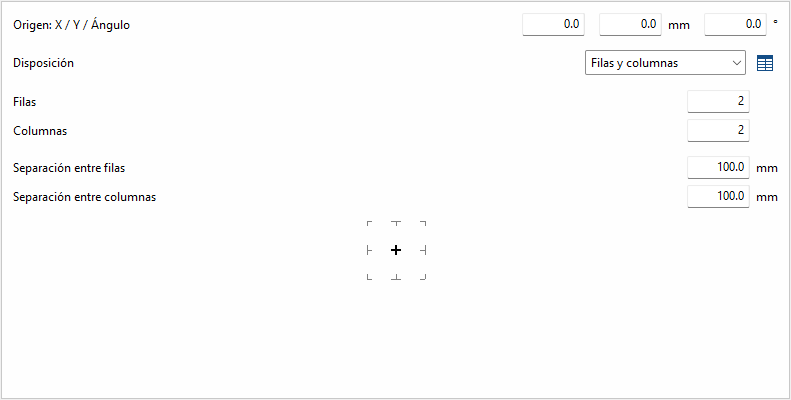
Rows and columns
Distributes the elements regularly in rows and columns, defining the number of elements per row and column and the spacing between them. This is a practical option for homogeneous configurations.
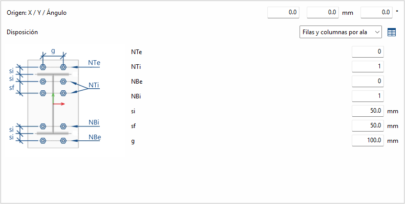
Rows and columns per flange
Typical distribution of end plates in I-sections. In the "End plate" operation, the edge of the bar that is joined to the plate is known, so it doesn't need to be inserted. In other operations, the edge between flange centres is requested.
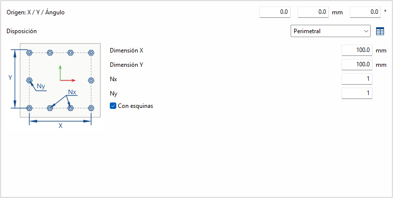
Perimeter
Given the dimensions "X" and "Y" of a rectangle, it allows the elements to be placed optionally in the corners, and the rest of the elements are distributed along each side according to the number indicated.
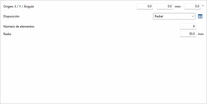
Radial
Given a radius and the number of elements, these are placed radially.
| Best practice: |
|---|
| Next to each option, except for "by coordinates", there is a button to convert the layout into a list of coordinates, allowing you to easily make changes if desired. |