

"Documents" tab interface
The CYPE Connect user interface is similar to that of other CYPE tools and features a system of dockable windows that can be customised to adapt the work area to the project’s requirements.
In the top left-hand corner of the screen, there are two separate tabs: "Model" and "Documents". The "Documents" tab displays the following sections:
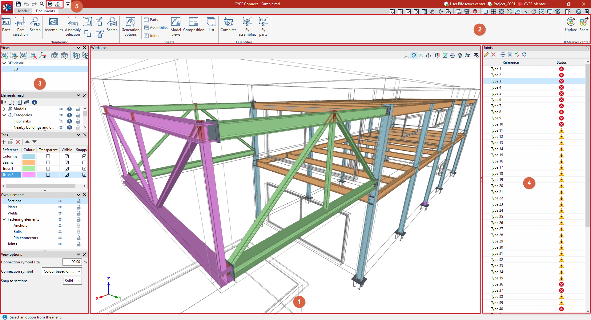
- The work area is located in the centre of the screen, and this is where all the project elements are entered, edited and viewed in 3D.
- The main toolbar contains various functions: you can number parts and assemblies, generate part sheets, assembly sheets, connection sheets or model views, create a sheet layout, access the sheet report, obtain quantity reports for the program's elements, or link and share the project with a BIMserver.center project.
- On the left-hand side are several panels that allow you to define the project views, manage the visibility of read elements, tags and custom elements, and adjust the display options.
- On the right-hand side is the list of connections created in the model. From here, you can access the editing and design interface for each connection.
- In the top-left corner, the program provides tools for printing and/or exporting reports and files in manufacturing formats such as DSTV, STEP, IFC EM.11 or DXF for plates.
| Note: |
|---|
| Part and assembly numbering, and the generation of part and assembly drawings, are only available in "Manufacturing" mode, as is export to manufacturing formats. |
