Managing styles
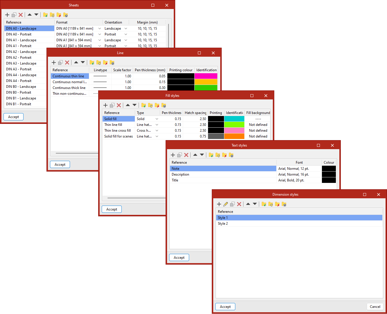
The options in the "Styles" panel, located on the top toolbar of the sheet editor, can be used to create custom libraries of sheets, lines, text, fills and dimensions.

The pop-up window that appears when you click on each of these options displays a list of the styles available in the project, with their parameters organised into columns.
Furthermore, using the options on the top toolbar of each style list, you can add new styles, edit them if necessary, duplicate them, delete them or reorder them in the list.
You can also export a style or a group of styles to files on the hard drive in various formats for use in other projects, as well as import them from other projects.
The styles created will be available for selection when inserting graphic elements.
Sheets
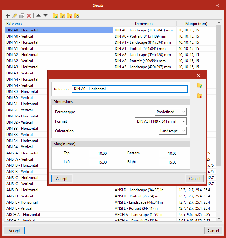
You can configure the list of available sheet styles.
For each of the "Sheets" in the list, you can set parameters such as the format, orientation and margins:
- Reference
- Dimensions
- Format type
- Format
- Orientation
- Margin
- Top
- Left
- Bottom
- Right
Page layout styles can be saved in an .oblpage file.
Linetype
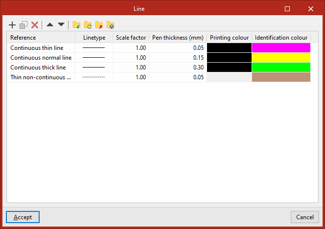
This is used to configure the list of available line styles.
For each "Line" style, you can configure the following settings:
- Reference
- Linetype
- Scale factor
- Pen thickness
- Printing colour
- Identification colour
Line styles can be saved in an .obllinpt file.
Fill styles
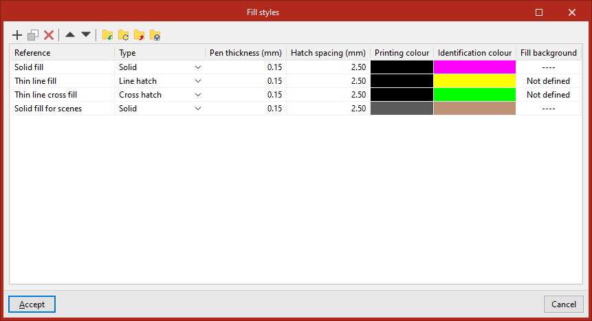
This is used to configure the list of available fill styles.
For each line style type under "Fill style", the following is specified:
- Reference
- Type (Solid/Line hatch/Inverted line hatch/Cross hatch)
- Pen thickness
- Hatch spacing
- Printing colour
- Identification colour
- Fill background
Fill styles can be saved to an .oblfillpt file.
Text
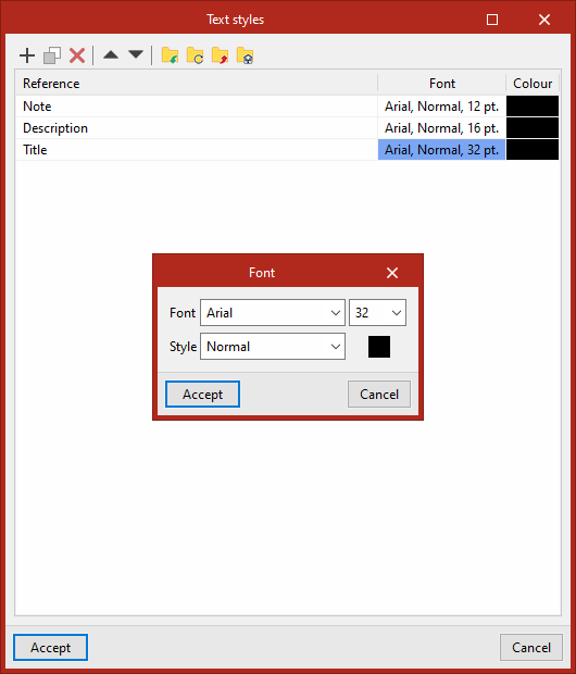
This is used to configure the list of available text styles.
Each "Text" style specifies:
- Reference
- Font (including the font size and its "Style")
- Colour
Text styles can be saved in an .obltxtpt file.
Dimension
This is used to configure the list of available dimensions.
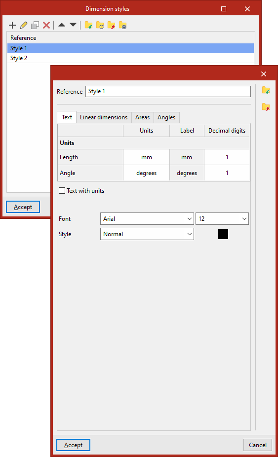
When editing each "Dimension" style, the program displays four tabs: "Text", "Linear dimensions", "Areas" and "Angles". In each of these, you can adjust parameters such as the lines and symbols to be used, or the thickness of each part of the dimensions:
- "Text" tab
Configure the text for dimensions:- Select the "Units" to be used (specifying their representative "Label" and the number of decimal places to be used) for "Length" and "Angle" measurements. When this "Text with units" option is enabled, the dimension text displays the units.
- You can also set the "Font", its size, "Style" and colour.
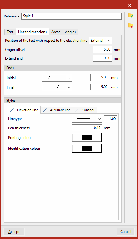
- "Linear dimensions" tab
Configure the lines and symbols used to create the dimension representation:- Specify the "Position of the text with respect to the elevation line", whether it is outside, centred or inside.
- Enter the values for "Origin offset" and "Extend end".
- Select the symbols for the "Initial" and "Final" "Ends", as well as their size
- Finally, define the "Styles" (including "Linetype", "Pen thickness", "Printing colour" and "Identification colour") of the:
- Elevation line
- Auxiliary line
- Symbol
- "Areas" tab
Configure the display of area dimensions:- First, you are asked whether you want to "Draw the polygon that defines the area"
- Next, define the styles (including "Stroke", "Pen thickness", "Print colour" and "Identification colour") for:
- The "Polygon" representing the defined area, including the "Line" and its "Fill"
- The "Text box" for the area dimension, also including the "Line" and an optional "Fill".
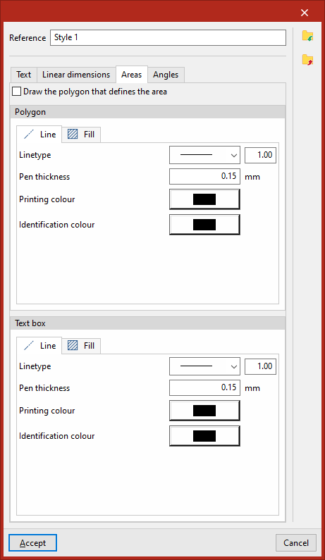
- "Angles" tab:
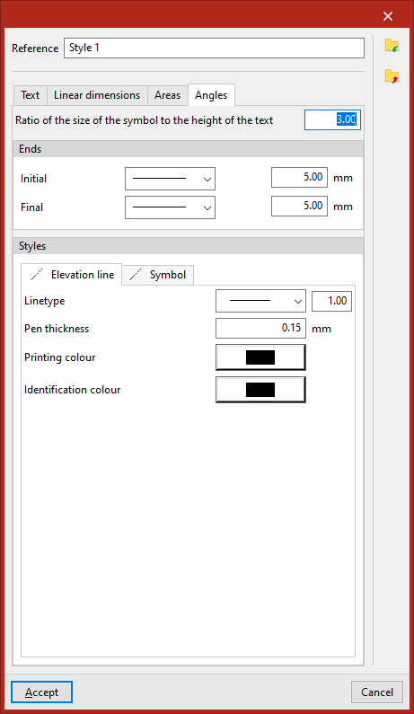
Configure angle dimension elements:- Enter the "Ratio between symbol size and text height".
- Select the symbols for the "Initial" and "Final" "Ends", as well as their size.
- Finally, define the "Styles" (including "Linetype", "Pen thickness", "Printing colour" and "Identification colour") of the:
- Elevation line
- Symbol
Dimension styles can be saved in an .obllinemeasurept file.