
Working environment
The CYPE Connect working environment follows the style of other CYPE modelling tools.
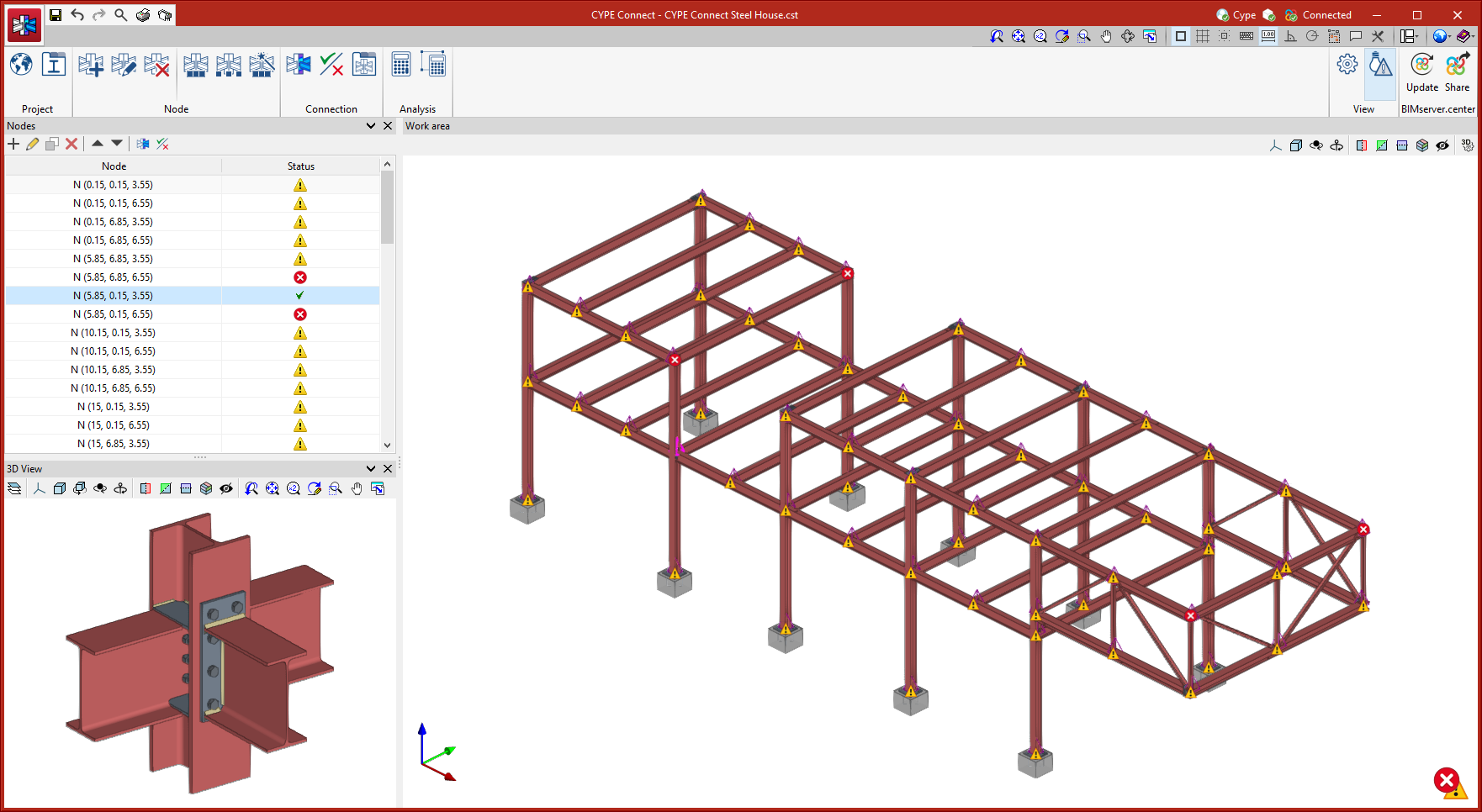
The top toolbar contains the main features for creating project libraries, creating and managing the nodes to be analysed, and editing and analysing the connections.
The model viewing area is located on the right-hand side of the main interface and allows users to select the analysed connections, as well as to view all the elements of the project in 3D.
The list of existing nodes in the project is located on the left-hand side. Any element selected in the 3D model is highlighted in the list and vice versa. Also, the program notifies users of the status of each connection by means of warning symbols.
A detailed view of the node selected in the list or in the 3D model is displayed in the bottom left corner.
Getting started
CYPE Connect allows users to work both by creating new nodes and entering forces and combinations manually, and by importing structural BIM models, which the program will interpret in order to generate nodes automatically. CYPE Connect can import the nodes and forces of steel and timber structures developed in CYPECAD and CYPE 3D.
| More information: |
|---|
| More information on how to start a project in CYPE Connect can be found in the CYPE Connect Quickstart guide videos. |