

Beam editor
The beam editor allows users to review the internal forces, design, and checks automatically performed by the program for all beams in the job. Using the editor, you can modify the reinforcement or steel sections used and verify all the changes made, then generate detailed check reports.
Beam editor interface
The interface of the beam editor includes the following areas and features:
Top toolbar
- At the top of the window, various editing and verification tools are available for the beams in the displayed frame.
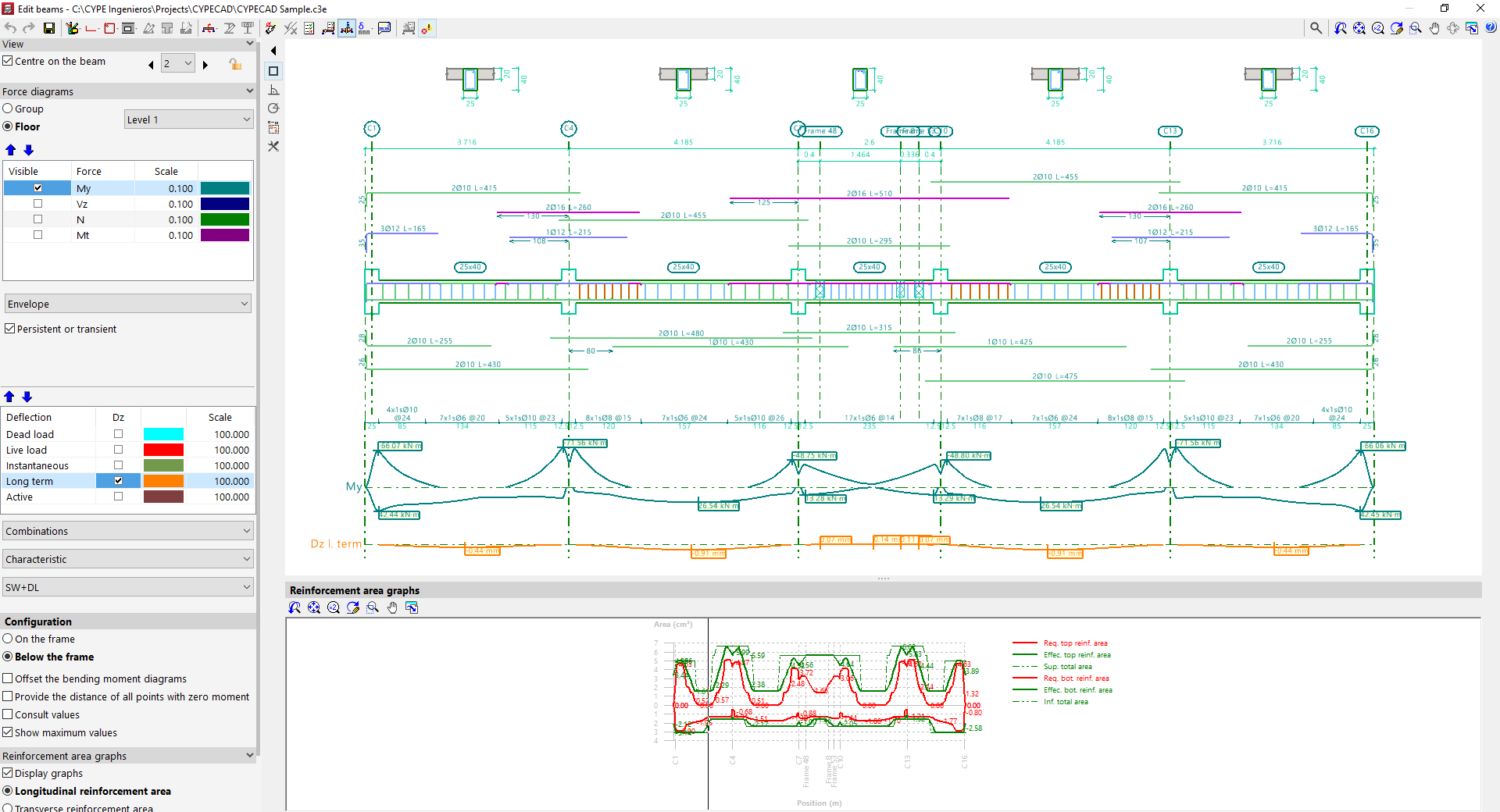
Viewers
- The main viewer in the upper right displays a longitudinal section view of the frame being edited. For reinforced concrete beams, it shows the longitudinal and transverse reinforcement generated after calculation. At the top, the generated cross sections are also shown.
- The secondary viewer at the bottom displays the "Reinforcement area graphs". The required area is shown in red, and the effective area of the placed reinforcement in green. The most critical or most used points in terms of reinforcement are those where the effective reinforcement graph is closest to the required reinforcement graph.
Side options panel
- On the left side, in the "Display" section, the program indicates the "Group" and the "Frame" currently shown in the viewer. The "Centre on beam" option allows you to centre the view on the desired beam, while activating "Plan view of frames" adds a schematic plan view. Clicking the left and right arrows allows you to navigate to the next group, frame, or beam. It is also possible to lock the reinforcement of the frame using the corresponding button. This will prevent the program from modifying the frame’s design in subsequent analyses, but it will not prevent manual edits in the editor.
- In the "Force diagrams" section, visibility of various internal forces is enabled, along with their scale and colour, such as the bending moment, shear force, axial force, or torsional moment.
- The lower dropdown menu lets you choose whether to view the "Envelope" of forces or one of the available "Load cases" or "Combinations"
- If the options "ULS and SLS checks at critical point", "ULS and SLS checks at a point", or "Check deflection in spans" are selected at the top, additional options for "Deflection" appear in this side panel, which can be reviewed in the same way as the force diagrams.
- In the "Configuration" subsection, you can choose whether the force diagrams are shown "Above the frame" or "Below the frame". Additional options include "Offset bending moment diagrams", "Mark zero moment points", and "Show values", which allows hovering over the diagram to see the force value at a specific section, as well as "Show maximum values".
- In the "Reinforcement area graphs" section, the "Show graphs" option toggles the display of the secondary viewer. Users can select whether to display the "Longitudinal reinforcement area" or the "Transverse reinforcement area", and whether to show it "By resistance and minimum ratios" or only "By resistance". It's also possible to "Show area values" in the viewer by enabling the last option.