

Editing the frame drawing
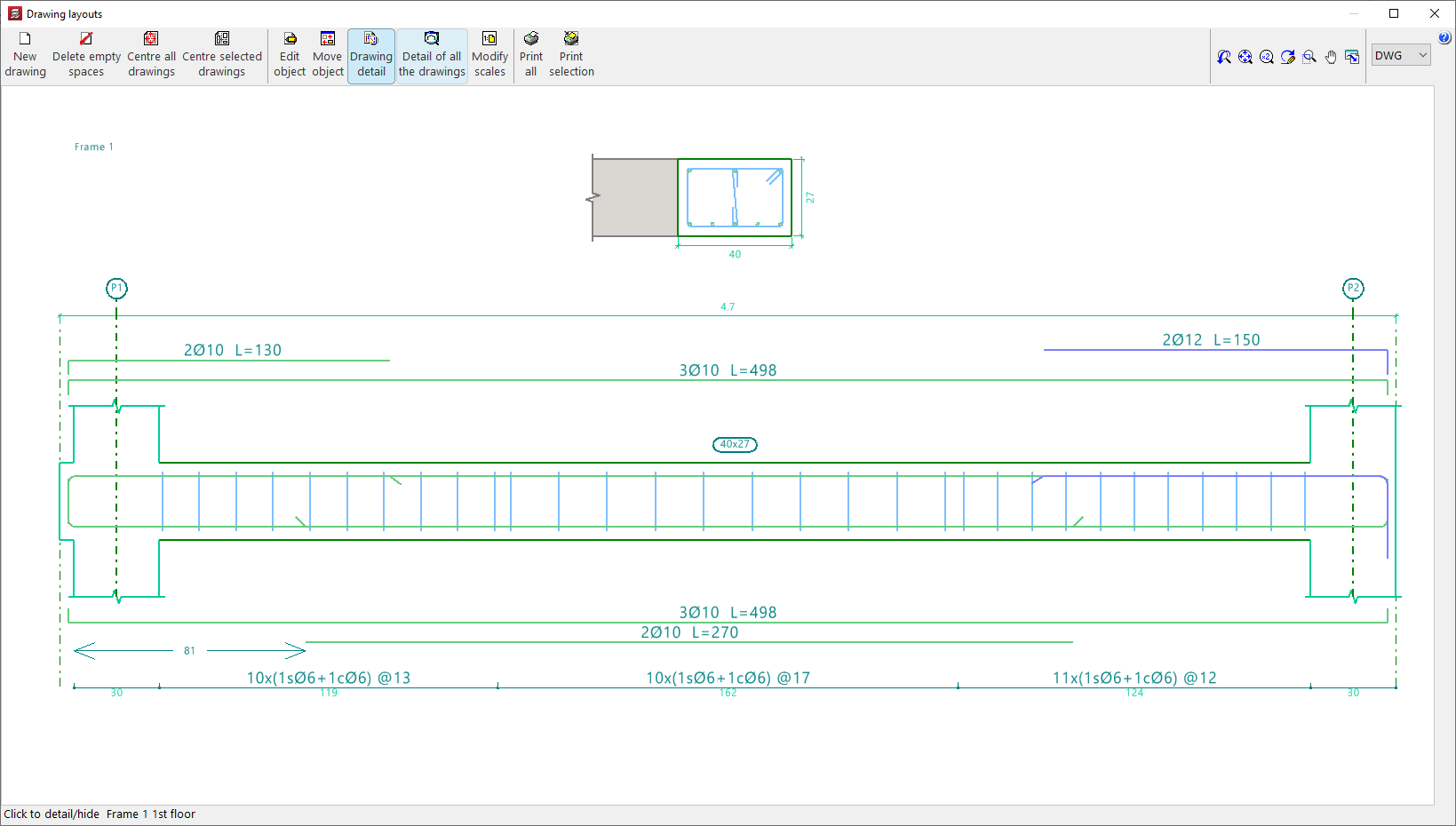
The frame drawing provides detailed information on the sections and reinforcement of the beams and frames of the structure. This drawing can be obtained after analysing the job.
The drawings are configured by adding or editing a drawing using the tools in the "Drawing selection" window, which appears when you use the "Drawings" option in the top toolbar or the "File" menu in the general interface.
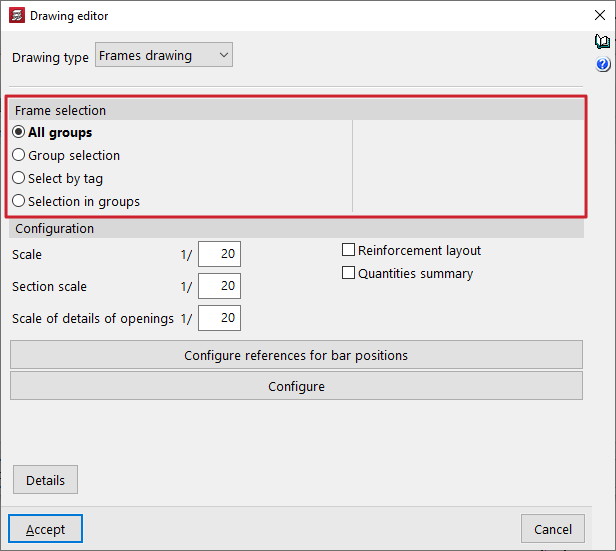
In the case of a "Frame drawing" type drawing, the editing options are as follows:
Frame selection
In this section, you can choose the frames you want to represent in the drawings. These can be:
- All groups
- Generates the frame drawings for all groups in the project.
- Group selection
- Generates the drawings for the frames located between the groups selected in the "Up to group" and "From group" drop-down menus, both included.
- Selection by tag
- Generates the drawings for the frames located between the groups selected in the drop-down menus and associated with the "Tags" indicated. Labels are managed from the "Tags" panel, within the "Groups" menu of the "Beam input" tab.
- Selection in groups
- Generates the drawings for the frames selected one by one in the "Frame selection" pop-up window.
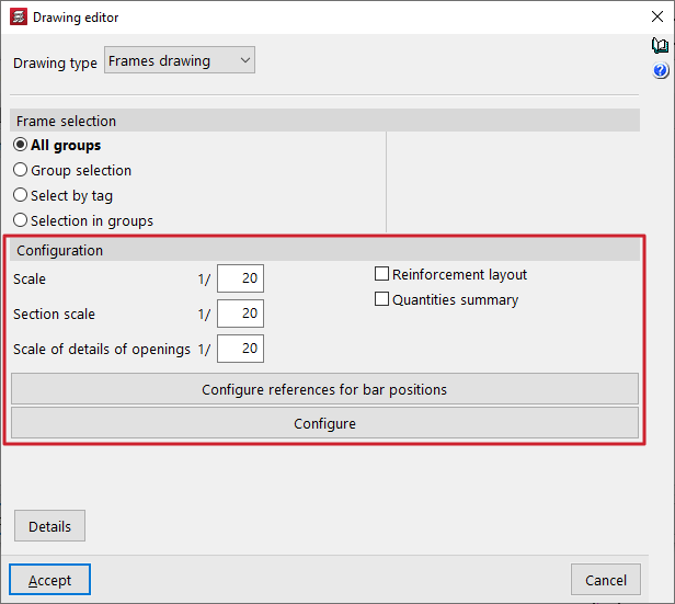
Configuration
In this section, you can choose the frames you want to represent in the drawings. These can be:
- Scale
Defines the scale of the longitudinal section of the frames. - Section scale
Defines the scale of the cross-section of the frames. - Scale of details of openings
Defines the scale of the details of the openings in the beams. - Reinforcement layout (optional)
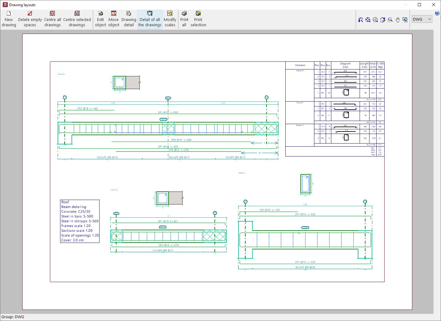
Checking this box adds position marks (by default, the letter P) that appear in the reinforcement texts and allow you to detail the layout of the frames' reinforcement. These position marks, accompanied by a number, reference the bar or bars on which they are located with respect to a table that the program places in the upper right corner of the drawing.
If you do not want to perform this detailed layout, do not tick this box. Even if it is not checked, you can still obtain the measurement summary. - Measurement summary (optional)
- Checking this box adds a table with a measurement summary of the reinforcement in the frames in the drawing. It includes information on the total lengths and weights for each diameter, as well as the total weight of all the reinforcement.
The "Configure references for bar positions" and "Configure" options can be used to make the following additional adjustments:
Configure references for bar positions
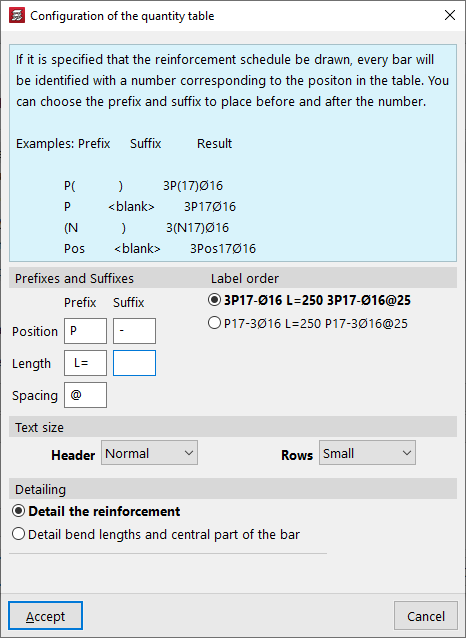
If the "Reinforcement detailing" box is checked to specify that the bars should be detailed, each bar is identified with a number corresponding to its position in the table. A prefix and suffix can be specified to be placed before and after this number.
These tags can be configured in the window that appears when you click on "Configure references for bar positions":
- Prefixes and suffixes
You can define the prefixes and suffixes used in the composition of the labels:- Position (Example: prefix "P", suffix "-")
- Length (Example: prefix "L=")
- Separation (Example: "@")
- Label order
You can select the order of labels from the following two schemes:- 3P17-Ø16 L=250 3P17-Ø16@25
- P17-3Ø16 L=250 P17-3Ø16@25
Meaning: 3 bars with a diameter of 16 mm in position 17, with a length of 250 mm / separated every 25 cm.
- Text size
Defines the size of the "Header" and "Rows" texts. - Detailing
In this section, you can select whether you want to "Detail the reinforcement" or "Detail bend lengths and the central part of the bar", in which case you can optionally "Indicate bend lengths".
Options in the "Configure" window
Clicking on the "Configure" button opens a window with three tabs containing different configuration options.
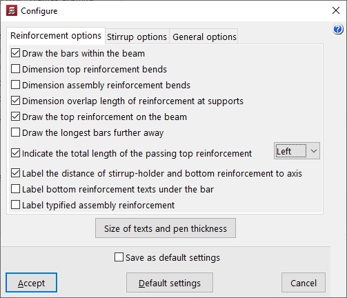
In the "Reinforcement options" tab, the program offers the following configuration options for the longitudinal reinforcement of beams:
- Draw the bars within the beam
- Dimension top reinforcement bends
- Dimension mounting reinforcement bends
- Dimension length of reinforcement overlaps at supports
- Draw the top reinforcement on the beam
- Draw the longer bars further away
- Indicate the total length of the passing top reinforcement (Left / Right / Both)
- Label the distance of stirrup-holder and bottom reinforcement to axis
- Label bottom reinforcement texts under the bar
- Label typified assembly reinforcement
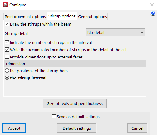
Then, in the "Stirrup options" tab, the program offers the following configuration options for the transverse reinforcement of the beams:
- Draw the stirrups within the beam
- Stirrup detail (No detail / Below the section / To the right of the section)
- Indicate the number of stirrups in the interval
- Write the accumulated number of stirrups in the detail of the cut
- Provide dimensions up to external faces
- Dimension (the positions of the stirrup bars / the stirrup interval)
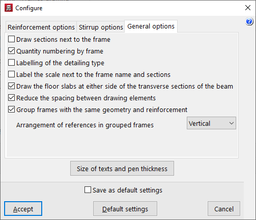
Finally, in the "General options" tab, the program offers the following general configuration options for frame drawings:
- Draw sections next to the frame
- Quantity numbering by frame
- Labelling of the detailing type
- Label the scale next to the frame name and sections
- Draw the floor slabs at either side of the transverse sections of the beam
- Reduce the spacing between the drawing elements
- Group frames with the same geometry and reinforcement
- Group frames with the same geometry and reinforcement (Horizontally / Vertically)
| Note: |
|---|
| To optimise the space used in the drawings, you can place the "Stirrup detail > To the right of the section" (instead of "Below the section") and check the "Reduce the spacing between drawing elements" option. This allows you to compact the drawing elements and even reduce the number of sheets needed to accommodate the drawings for the selected frames. |