Entering consumptions: sprinklers, fire hose reels and emitters
In the "Installation" tab, in the "Consumption" group of the main toolbar, the consumption of the hydraulic fire extinguishing system can be defined and entered: sprinklers, fire hose reels, emitters and wet standpipe outlets:

Sprinklers
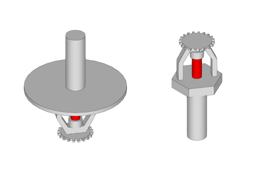
Enters sprinklers into the model one at a time along with their associated protection area.
| Nota: |
|---|
| To enter sprinkler groups or to generate them automatically from the geometry of the spaces, together with the distribution pipes, the corresponding options can be used in the "Distribution" group in the upper toolbar. |
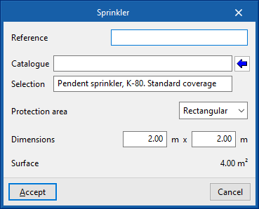
When entering a sprinkler, the following parameters can be configured:
- Reference
Sprinkler reference. - Catalogue / Selection
The program can be used to select a sprinkler from the manufacturer's catalogues included in the Open BIM Database. These can be downloaded from the "Catalogue management" option in the "Project" group. - Protection area
Enters the parameters defining the area protected by the sprinkler, which can be rectangular or circular. The program reports the "Surface" of the protected area obtained based on these parameters.- Rectangular (Dimensions)
- Circular (Radius)
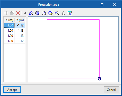
When editing a previously entered sprinkler, the geometry of the generated "Protection area" can be modified by entering the "X" and "Y" coordinates defining the points of its perimeter relative to the sprinkler.
The "3D layout" of the sprinkler can also be modified by editing the following parameters:
- X, Y, Z
Absolute coordinates of the sprinkler position in the model. - Ux, Uy, Uz / Vx, Vy, Vz
Components of the U and V vectors that determine the sprinkler orientation plane.
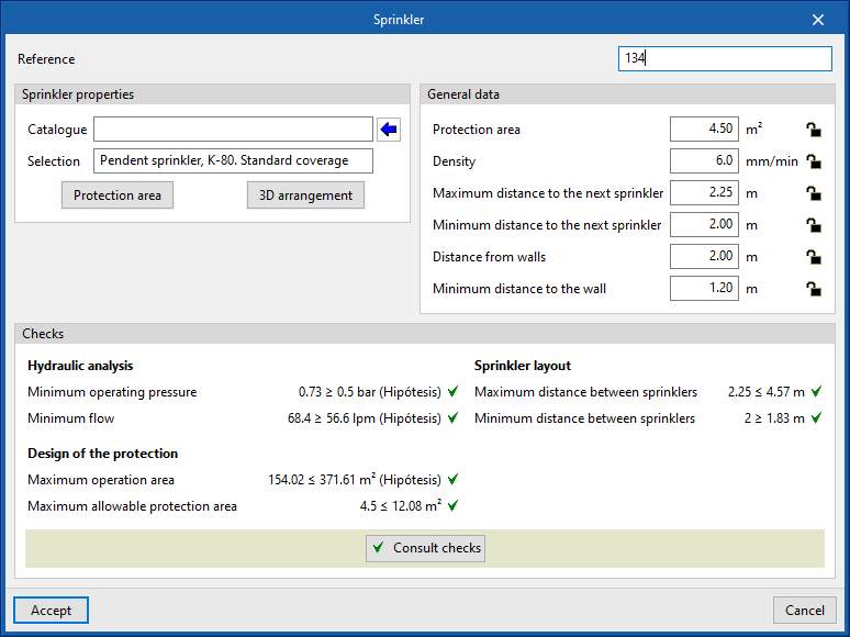
During the analysis, the program displays the following general data. This data can be locked or unlocked. If they are locked, the users can impose their value. By keeping them unlocked, the program can modify them by taking information from the model and the analysis results:
- Protection area
- Density
- Maximum distance to the next sprinkler
- Minimum distance to the next spinkler
- Distance from walls
- Minimum distance to the wall
The checks to be carried out on the sprinklers can be defined for each type of space in "General options", in the "Project" group in the top toolbar. After the analysis, the program allows the verification of each of the checks defined in the sprinkler editing panel to be consulted.
Fire hose reels
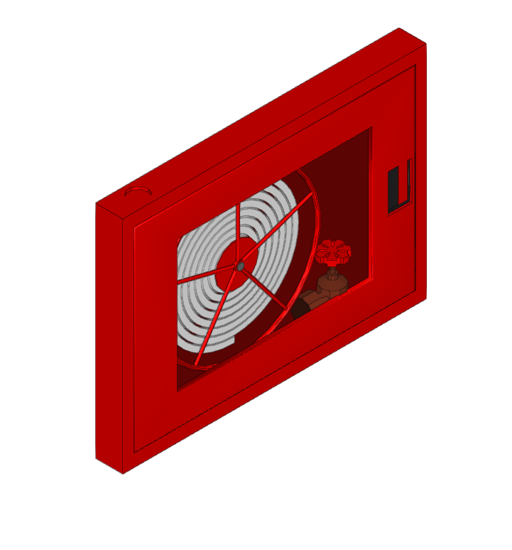
Inserts a fire hose reel.
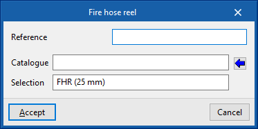
When entering or editing a fire hose reel, the following parameters can be configured:
- Reference
Fire hose reel reference. - Catalogue / Selection
The program can be used to select a fire hose reel from the "Manufacturer's catalogues" if available, or from the "Generic elements library" using the wizard available on the right. These types of elements can be created and edited from the "Catalogue management" and "Generic elements library" options, respectively, within the "Project" group. - Checks
Selects the checks to be carried out on the fire hose reel. The Checks to be carried out on the fire hose reels" can be defined in "General options" in the "Project" group of the top toolbar. This section appears after selecting a fire hose reel from the catalogue.
The checks to be carried out on fire hose reels can be defined for each type of space in "General options" in the "Project" group of the top toolbar.
Emitters
Inserts a generic emitter.
The emitters allow the simulation, analysis and hydraulic design of any element of a fire extinguishing installation (sprinklers, fire hose reels, hydrants, etc.), without depending on the geometric and hydraulic restrictions of the sprinklers and fire hose reels that are entered through the other options in this group.
When entering or editing an emitter, the following parameters can be configured:
- Reference
Emitter reference. Identifies the element entered in the report. - K-Factor
Discharge factor of the emitter for calculating the flow rate.
The program does not perform any checks on the emitters but, thanks to the EPANET calculation engine, it is able to perform the hydraulic analysis of the designed system. Furthermore, on the program interface, the flow and pressure data obtained for each of the emitters entered can be displayed.
Wet riser
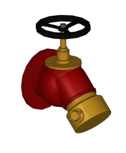
Enters a wet riser outlet.
This element acts in the same way as a sprinkler, fire hose reel or emitter, being connected at any point in the system and assigned to the desired design scenarios in order to obtain the flow rate and pressure resulting from the analysis.
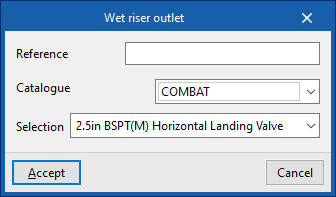
When entering or editing an outlet for a wet riser, the following parameters can be configured:
- Reference
Reference for the wet riser outlet. - Catalogue / Selection
The program can be used to select a wet riser outlet from the manufacturer's catalogues included in the Open BIM Database. These can be downloaded from the "Catalogue management" option in the "Project" group.
As with the emitters, the program does not carry out any regulatory checks on the wet riser outlets, but, thanks to the EPANET analysis engine, it is able to carry out the hydraulic analysis of the designed system. Moreover, on the program's interface, it is possible to visualise the flow and pressure data obtained for each of the wet riser outlets entered.


