Defining the project's general options
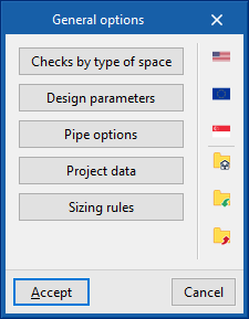
Within the "Installation" tab, in the "Project" group of the main toolbar, the "General options" of the project can be defined:

The following options are available:
- Checks by type of space
- Checks to be carried out on the fire hose reels
- Design parameters
- Pipe options
- Valves
- Project data
- Sizing rules
- Prescription options
By using the configuration import options available on the right-hand side of the "General options" panel, this data can be generated automatically for different national and international codes, such as the following:
 NFPA 13 and NFPA 14 (United States)
National Fire Protection Association. Standard for the Installation of Sprinkler Systems / Standard for the Installation of Standpipe and Hose Systems EN 12845:2016 (European Union)
Fixed firefighting systems - Automatic sprinkler systems - Design, installation and maintenance CP 52:2004 (Singapur)
Singapore Standard - Code of practice for automatic fire sprinkler system
For systems in the rest of the world or for specific analyses, the checks can be entered and configured manually in a customised way.
The other options in the right-hand column can be used to import and export the complete configuration of the "General options" panel to files on disk, as well as to select a file with initial values for the creation of a new job.
Details of the above-mentioned features are given below.
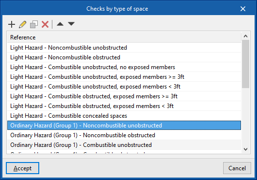
Checks by type of space
This section activates and configures the checks to be carried out for each type of space entered according to its risk.
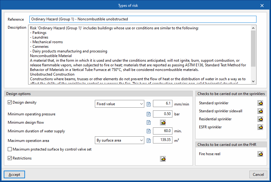
For each type of space, the program allows the following parameters to be defined:
- Reference
Reference of the type of space, according to its risk. - Description
Description of the type of space. - Design options
For each of the following options and checks, a configurable descriptive text can be entered in addition to the numerical value associated with them:- Design density (Fixed value/ Defined by points) (optional)
Amount of water discharged per unit time by the sprinkler installation over a given area. It can be expressed with a fixed value or by a curve that obtains the design density to be considered from the area of operation of the active sprinklers. - Minimum operating pressure
Minimum pressure to be achieved in sprinklers. - Minimum design flow
Minimum permissible flow rate to be provided by sprinklers. To be taken from the maximum obtained from the three equations shown:- Q = k * (Pmín)1/2 (optional)
Flow rate (Q) expressed as a function of the discharge factor (k), defined in the sprinkler type, and the minimum operating pressure at the sprinkler (Pmin). - Q = D * A (optional)
Flow rate (Q) expressed as a function of design density (D) and area of operation (A). - Fixed value (in units of volume/time) (optional)
This value is directly editable by the user.
- Q = k * (Pmín)1/2 (optional)
- Minimum duration of water supply (optional)
If the system is based on a tank, the tank shall be capable of supplying water for the minimum time set out in this section. - Maximum operation area (By surface area / By sprinklers)
Maximum value of the area of operation, expressed by surface area or by the number of sprinklers that are active. - Maximum protected surface by control valve set (optional)
If the installation has a control post, the area protected by the control post shall not exceed this value. - Restrictions
Sets installation restrictions, defining the type of response for each type of sprinkler. Sprinklers of different response types cannot be installed together, depending on whether or not the boxes at the bottom of the dialogue box are checked.- Type of sprinkler (Standard sprinkler / Standard sprinkler sidewall / Residential sprinkler / ESFR sprinkler / All types / Type of response (Standard / Rapid / All types)
- Allow for sprinklers with a different response to be installed (optional)
- Allow for the installation of "Residential sprinkler" with other types of sprinklers (optional)
- Design density (Fixed value/ Defined by points) (optional)
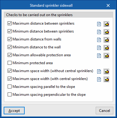
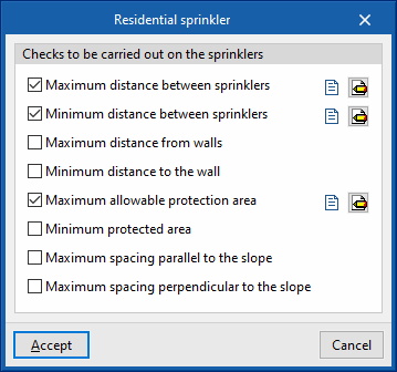
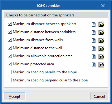
- Checks to be carried out on the sprinklers
The following checks can be activated and configured for the different sprinkler types: "Standard sprinkler", "Standard sprinkler sidewall", "Residential sprinkler", "ESFR sprinkler":- Maximum distance between sprinklers (Fixed value / Depending on the discharge density) (optional)
- Minimum distance between sprinklers (optional)
- Maximum distance from walls (Fixed value / Depending on the discharge density) (optional)
- Minimum distance to the wall (optional)
- Maximum allowable protection area (Fixed value / Depending on the discharge density) (optional)
- Minimum protected area (optional)
- Maximum space width (without central sprinklers) (optional) [only with "Standard sprinkler sidewall"]
- Maximum space width (with central sprinklers) (optional) [only with "Standard sprinkler sidewall"]
- Maximum spacing parallel to the slope (optional)
- Maximum spacing perpendicular to the slope (optional)
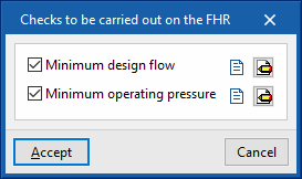
- Checks to be carried out on the FHR
The following checks can be activated and configured to be carried out on fire hose reels:- Minimum design flow
- Minimum operating pressure
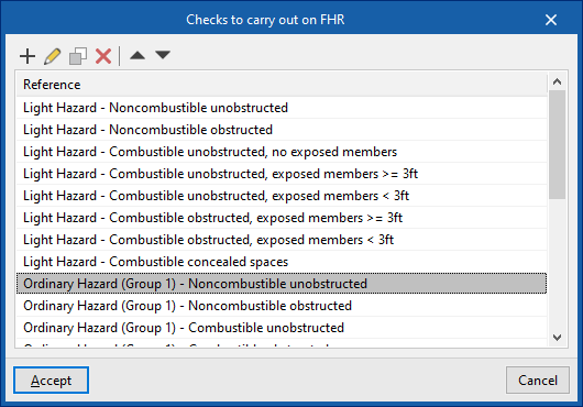
Checks to be carried out on the fire hose reels
In this section, the checks to be carried out on the fire hydrants equipped for each type of risk are activated and configured.
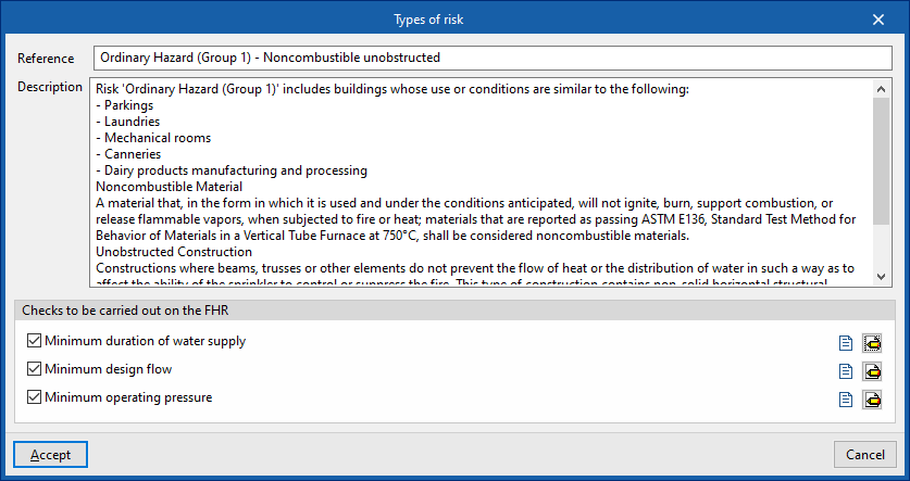
For each type of risk in the report, the program defines the following parameters:
- Reference
Reference of the type of risk. - Description
Description of the type of risk. - Checks to be carried out on the fire hose reels
The following checks can be activated and configured to be carried out on the fire hose reels:- Minimum duration of water supply
- Minimum design flow
- Minimum operating pressure
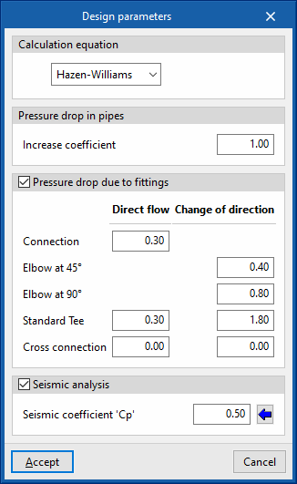
Design parameters
- Calculation equation
Selects the equation for calculating the pressure drop:- Hazen-Williams
The Hazen-Williams calculation method is one of the most widely used due to its simplicity of calculation, but it cannot be used with any liquid other than water. This is the default method selected. - Darcy-Weisbach
The Darcy-Weisbach calculation method is more accurate than the previous one, but more complex, due to the calculation of the friction factor. This method is required in certain specific cases by some standards, such as NFPA 13. The choice of this calculation method allows the following parameters to be set:- Specific gravity
Ratio of fluid density to water density at 4°C. - Relative viscosity
Ratio of the kinematic viscosity of the fluid to that of water at 20°C. - Precision
Convergence criterion used to indicate that the solution to the non-linear equation has not been found. The iterative calculation ends when the sum of all flow differences divided by the sum of all line flows is less than the number indicated in this section.
- Specific gravity
- Hazen-Williams
- Pressure drop in pipes
Inserts a safety coefficient which increases the pipe lengths to simulate pressure losses due to singular elements such as elbows, crosses, tees, valves, etc.- Increase coefficient
This value must be greater than the unit. For example, to represent a head loss increase of 15%, a value of 1.15 is entered.
- Increase coefficient
- Pressure drop due to fittings (optional)
By activating this option, fittings such as connections, elbows, tees or crosses are generated during the calculation according to the geometry of the network and can be displayed in the 3D representation of the system. Furthermore, in this section, the program can configure the head loss coefficient associated with the different types of fittings generated, both in the branch with direct flow and in the branch with change of direction, if applicable.- Connection (Direct flow)
- Elbow at 45º (Change of direction)
- Elbow at 90º (Change of direction)
- Standard Tee (Direct flow, Change of direction)
- Cross connection (Direct flow, Change of direction)
- Seismic analysis (optional)
By activating this option and setting the following parameter, users can enter and analyse seismic bracings in the installation using the options in the "Bracings" group of the main toolbar.- Seismic coefficient 'Cp'
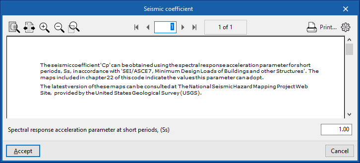
This can be entered directly or using the wizard on the right to obtain it from the "Spectral response acceleration parameter at short periods (Ss)", according to "SEI/ASCE 7, Minimum Design Loads of Buildings and other Structures".
- Seismic coefficient 'Cp'
Pipe options
- Checks
Activates and configures the following checks on the pipes:- Maximum velocity (optional)
Maximum velocity of the fluids permitted in pipes. - Maximum allowable pressure drop (optional)
Maximum allowable pressure drop ratio for any given pipe span, expressed as a percentage. If the pressure difference between the initial and final nodes is greater than the indicated value, a warning shall be displayed on the pipe warning that the span must be redesigned.
This option is used to quickly detect spans that, due to their dimensions, produce large head losses and therefore need to be redesigned. The default value is 40%.
- Maximum velocity (optional)
- Quantities
- Generate the support quantities (optional)
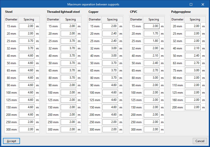
Activating this option automatically generates the measurement of the pipe supports from the geometry of the installation entered in the model. The option on the right configures this measurement by editing the "Maximum spacing between supports" for the different pipe materials and diameters.
- Generate the support quantities (optional)
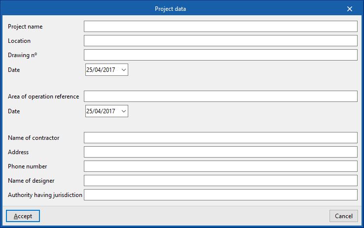
Project data
Incorporates the following project data into the program so that it can be used and displayed in the report composition:
- Project name
- Location
- Drawing reference / Date
- Area of operation reference / Date
- Name of contractor
- Address
- Name of designer
- Authority having jurisdiction
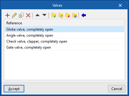
Valves
Defines types of valves. These elements can be entered in the model from the ‘’Valves‘’ option in the ‘’Distribution‘’ group of the main toolbar.
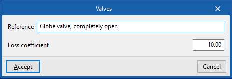
The data associated with each valve is as follows:
- Reference
Valve reference. - Loss coefficient
Pressure loss coefficient associated with the valve.
The wizard to the right of the top of the list can import ‘’Predefined valve types‘’ included in the program.
Sizing rules
Configures the design criteria used by the program by clicking on the "Design" option in the "Calculation" group of the main toolbar:
- Diameter / Sprinklers (optional)
The program will modify the diameter of the pipes according to the number of sprinklers it supplies.
Some diameters are only available for polypropylene pipes.
Prescription options
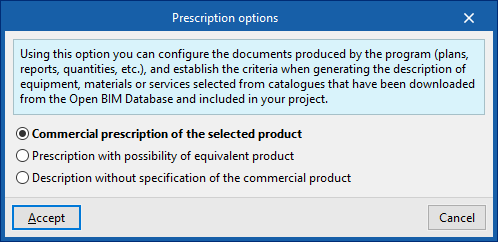
This option is used to configure the documents produced by the program (drawings, reports, quantities, etc.), establishing the criteria for generating the descriptions of the equipment, materials or services selected from the catalogues downloaded from the Open BIM Database and included in the project.
- Commercial prescription of the selected product
The description of the equipment, materials and services will prescribe the selected product exclusively. - Prescription with the possibility of an equivalent product
The description of the equipment, materials and services shall prescribe the selected product indicating the possibility of using an equivalent product. - Description without specification of the commercial product
The description of the equipment, materials and services shall not specify a particular commercial product.


