
Defining the general project options
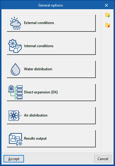
In the "Project" group of the main toolbar on the "Installation" tab, you can define the general options of the project:

The available options are as follows:
- External conditions
- Internal conditions
- Water distribution
- Direct expansion
- Air distribution
- Results output
These functions are detailed below.
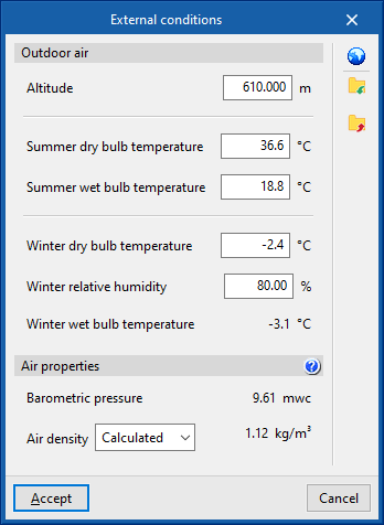
External conditions
Defines the external air conditions.
- Outdoor air
- Altitude (m)
- Dry-bulb temperature, summer (ºC)
- Wet-bulb temperature, summer (ºC)
- Dry-bulb temperature, winter (ºC)
- Relative humidity, winter (%)
- Wet-bulb temperature, winter (ºC)
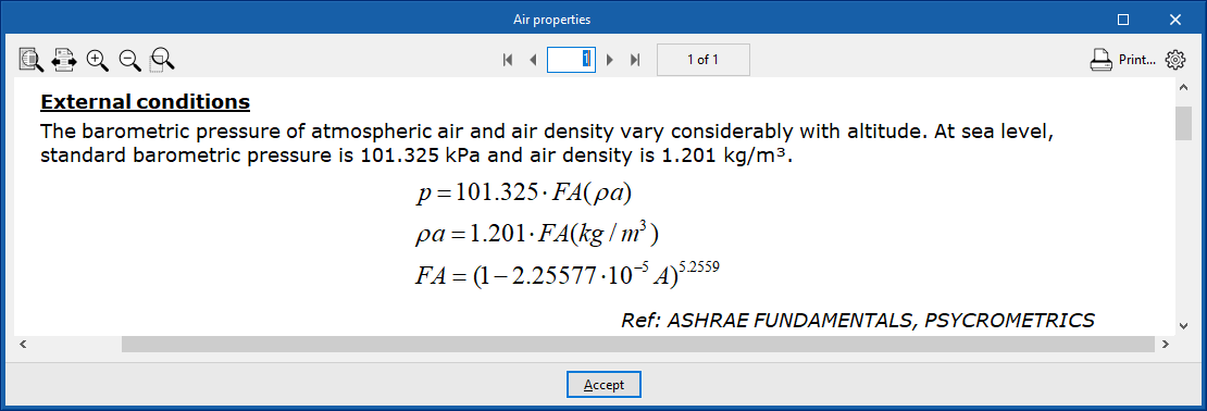
- Air properties
- Barometric pressure (mwc)
- Air density (Calculated/User-defined) (kg/m³)
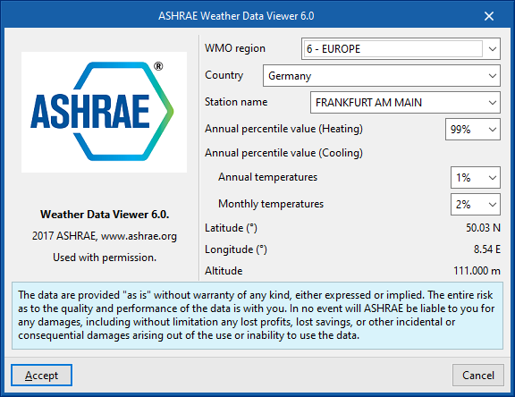
Climate data import
Outdoor condition data can be imported from the ASHRAE Weather Data Viewer 6.0 database using the button to the right of the "Outdoor conditions" window.
To import this data, the following parameters must be defined:
- WMO region
Defines the world region. - Country
Allows the country to be selected within the chosen region. - Station name
Allows the meteorological station to be selected within the chosen country.
From here, it is also possible to choose the percentile levels of the data to be imported:
- Annual percentile level (Heating)
Allows a level of 99.6% or 99% to be selected. - Annual percentile level (Cooling)
- Temperaturas anuales
Permite elegir un nivel de 0.4%, 1% o 2% para las temperaturas anuales. - Temperaturas mensuales
Permite elegir un nivel de 0.4%, 2% o 5% para las temperaturas mensuales.
- Temperaturas anuales
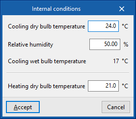
Internal conditions
Defines the indoor air conditions.
- Cooling dry-bulb temperature (ºC)
- Relative humidity (%)
- Cooling wet-bulb temperature (ºC)
- Heating dry-bulb temperature (ºC)
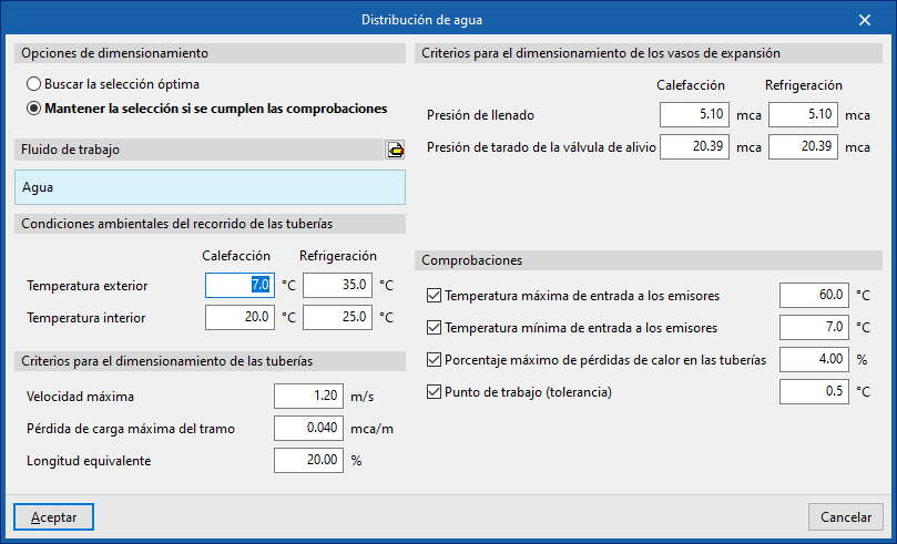
Water distribution
This section configures the sizing criteria for various elements of the water distribution system such as pipes and expansion vessels, and activates certain checks on them.
Design options
Allows the sizing process of the water distribution system elements to be adjusted:
- Search for the optimal selection
During the design process, the program will search for and select the smallest element in the series that meets all requirements. - Maintain the selection if checks are met
During the design process, the program will attempt to retain the element selected by the user. If the selected element meets the requirements, the program will not change it, even if there is a smaller one that also meets them. However, if the selected element does not comply, the program will replace it with the smallest element that does.
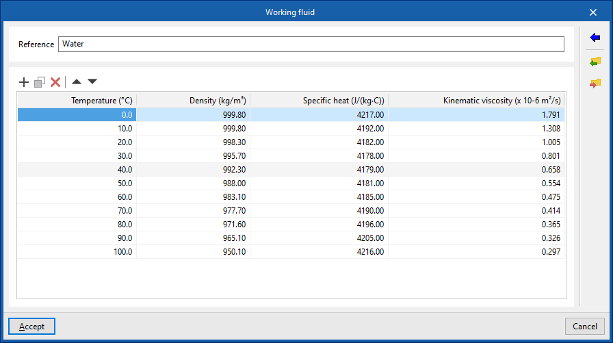
Working fluid
Defines the properties of the working fluid by reference and at different temperatures:
- Reference
- Working fluid properties table
- Temperature (ºC)
- Density (kg/m³)
- Specific heat (J/(kg·ºC))
- Kinematic viscosity (×10⁻⁶ m²/s)
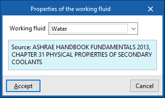
It is possible to import predefined values for water and for water with additives using the assistant to the right:
- Working fluid properties
- Working fluid (Water / Water with ethylene glycol / Water with propylene glycol)
Environmental conditions along the pipe route
- Outdoor temperature (ºC) (Heating / Cooling)
- Indoor temperature (ºC) (Heating / Cooling)
Pipe design criteria
- Maximum velocity (m/s)
- Maximum head loss per section (mwc/m)
- Equivalent length (%)
Expansion vessel design criteria
- Filling pressure (mwc) (Heating / Cooling)
- Relief valve setting pressure (mwc) (Heating / Cooling)
Checks
- Maximum inlet temperature to emitters (ºC) (optional)
- Minimum inlet temperature to emitters (ºC) (optional)
- Maximum heat loss percentage in pipes (%)
- Operating point (tolerance) (ºC)
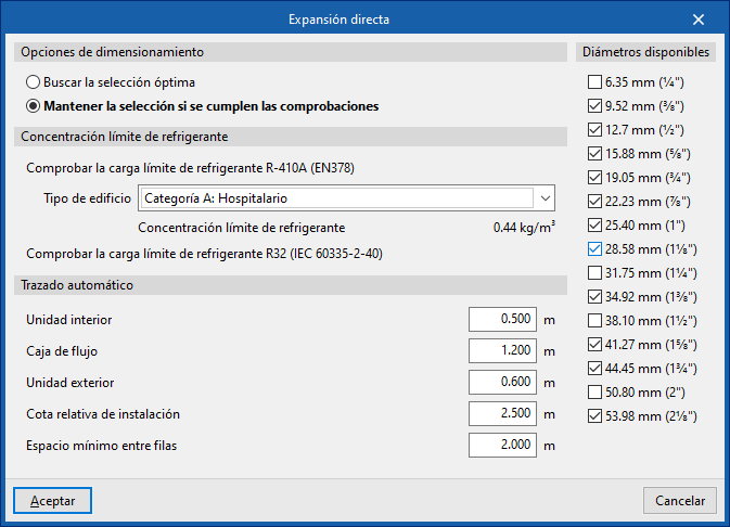
Direct expansion
Design options
Allows the design process of the direct expansion system elements to be adjusted:
- Search for the optimal selection
During the design process, the program will search for and select the smallest element in the series that meets all requirements. - Maintain the selection if checks are met
During the design process, the program will attempt to retain the element selected by the user. If the selected element meets the requirements, it will not be changed, even if there is a smaller one that also meets them. However, if it does not comply, the program will replace it with a suitable one.
Refrigerant charge limit concentration
This section allows the verification of the refrigerant charge limit.
To "Check the R-410A refrigerant charge limit (EN378)", select the "Building type" from the following:
- Category A: Hospital
- Category B: Residential, commercial, educational, public access
- Category C: Offices and administrative premises
- Category D: Industrial
Selecting a building type displays the associated "Refrigerant concentration limit".
It is also possible to "Check the R32 refrigerant charge limit (IEC60335-2-40)".
Automatic routing
Configures the distances used by the "Automatic routing (VRF)" option in the "Calculation" group.
- Indoor unit
- Flow box
- Outdoor unit
- Relative installation level
- Minimum spacing between rows
Available diameters
Allows you to define which refrigerant line diameters are available by activating or deactivating the corresponding boxes.
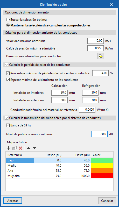
Air distribution
This section configures the design criteria for various air distribution system elements, such as ducts, and activates certain checks on them.
Design options
Allows the design process of the air distribution system elements to be adjusted:
- Search for the optimal selection
During the design process, the program will search for and select the smallest element in the series that meets all requirements. - Maintain the selection if checks are met
During the design process, the program will attempt to retain the element selected by the user. If it meets the requirements, it will not be changed. Otherwise, it will be replaced with a compliant one.
Duct design criteria
- Maximum allowable velocity (m/s)
- Maximum allowable pressure drop (Pa/m)
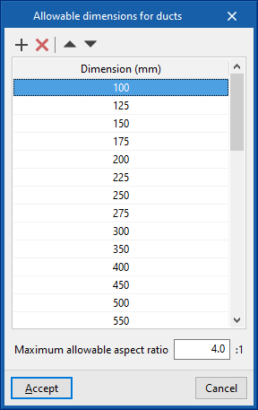
- Permissible duct dimensions
- Dimension (mm)
- Maximum allowable aspect ratio (n:1)
Calculate duct heat loss (optional)
Enables the thermal analysis of heat loss through air ducts when calculating or sizing the installation.
- Maximum percentage of heat losses in ducts (%)
- Minimum insulation thickness for ducts
- Defined for ducts in the following categories:
- Installed indoors (Heating, Cooling)
- Installed outdoors (Heating, Cooling)
- Further down, enter the "Thermal conductivity of reference material".
- Defined for ducts in the following categories:
Calculate airborne noise transmission through duct system
Enables acoustic calculation in air ducts when calculating or designing the installation.
- 63 Hz band (optional)
- Minimum sound power level
- Acoustic map
- Reference / From / To / Colour
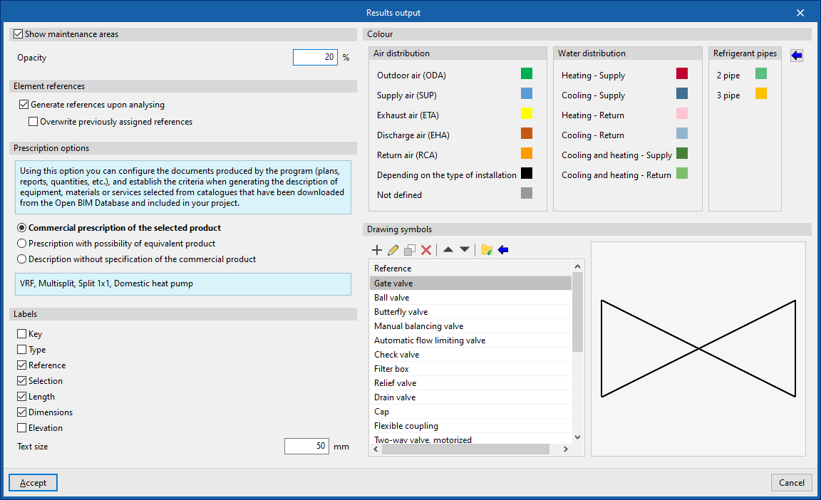
Results output
Allows you to configure different options related to the programme’s results output:
Show maintenance areas (optional)
Displays maintenance areas near equipment when this information is available.
- Opacity
Element references
Allows automatic generation of element references to be activated or deactivated.
- Generate references when calculating (optional)
- Overwrite previously assigned references (optional)
Specification options
Configures the documentation produced by the program (drawings, lists, measurements, etc.), establishing the criteria for generating descriptions of equipment, materials or services selected from the catalogues downloaded from Open BIM Database and included in the project.
- Commercial specification of the selected product
Descriptions will specify only the selected product. - Specification with equivalent product option
Descriptions will specify the selected product and indicate the possibility of using an equivalent. - Description without specifying a commercial product
LaDescriptions will not specify a particular commercial product.
Labels
Configures the information labels displayed over elements.
- Legend (optional)
- Type (optional)
- Reference (optional)
- Selection (optional)
- Length (optional)
- Dimensions (optional)
- Level (optional)
- Text size
- Colour
Colour
Allows modification of the display colour (on screen and in drawings) for elements of the following categories:
- Air distribution
- Outdoor air (ODA)
- Supply air (SUP)
- Extraction air (ETA)
- Exhaust air (EHA)
- Return air (RCA)
- According to the type of installation
- Undefined
- Water distribution
- Heating - Supply
- Cooling - Supply
- Heating - Return
- Cooling - Return
- Cooling and heating - Supply
- Cooling and heating - Return
- Refrigeration lines
- 2 pipes
- 3 pipes
The button on the right restores the "Default values".
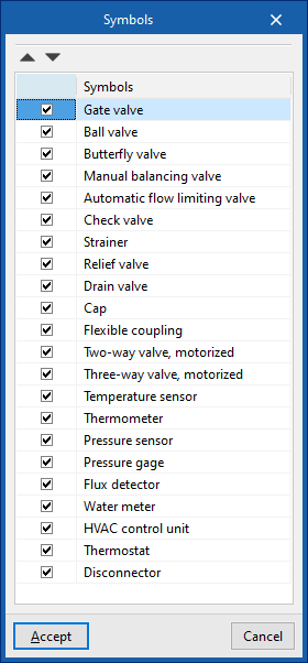
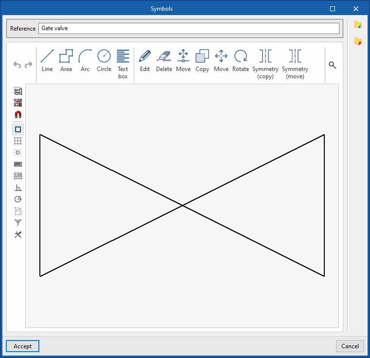
Symbols for drawings
Create symbols for different elements in the drawing using a graphic editor where you can insert lines, areas, arcs, circles and text boxes.
The program also offers the possibility of importing a series of predefined symbols using the wizard in the top toolbar.
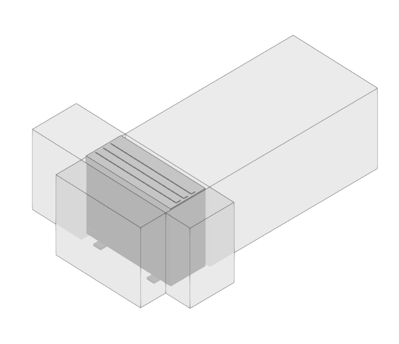
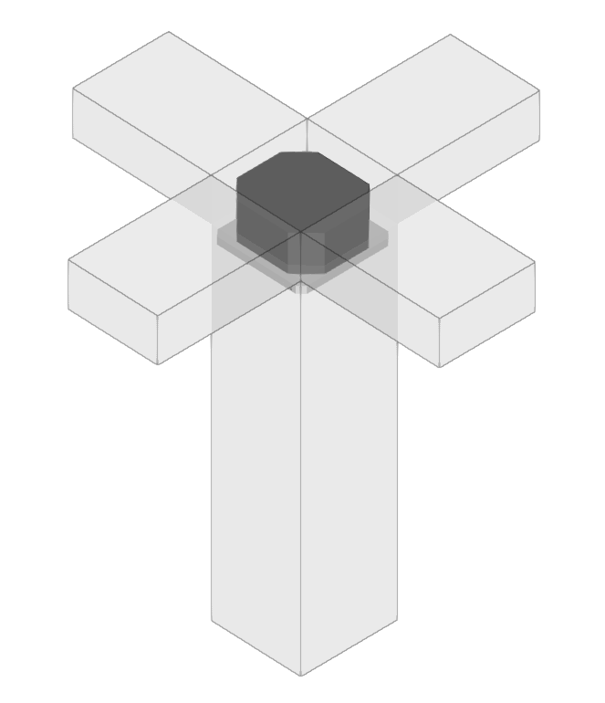
Maintenance areas for various units