Entering installation elements
In the "Installation" group of the main toolbar, the following elements can be defined and entered:

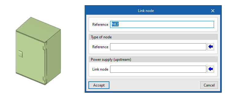
Link nodes
Enter a link node in the model after specifying the following parameters:
- Reference
- Type of node
- Reference
- Power supply (upstream)
- Link node
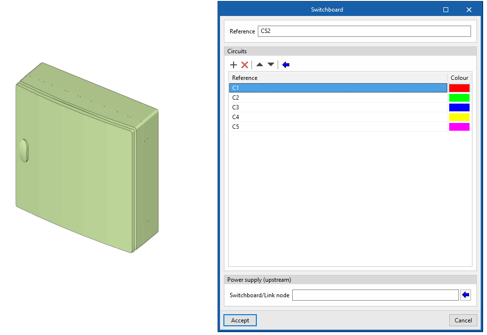
Switchboards
Enters a switchboard or sub-switchboard in the model after specifying the following parameters:
- Reference
- Circuits
- Reference
- Colour
- Power supply (upstream)
- Switchboard/Link node
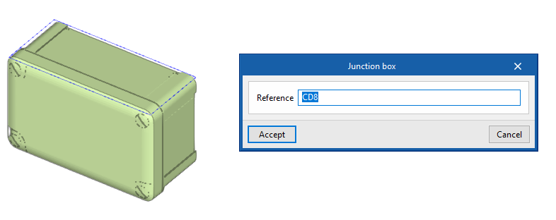
Junction box
Enters a junction box in the model after specifying the following parameters:
- Reference
Then it is possible to automatically route the conduits from a junction box to the selected receivers with the "Generate branches" option.
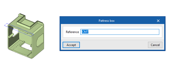
Pattress box
Enters a pattress box into the model after specifying the following parameters:
- Reference
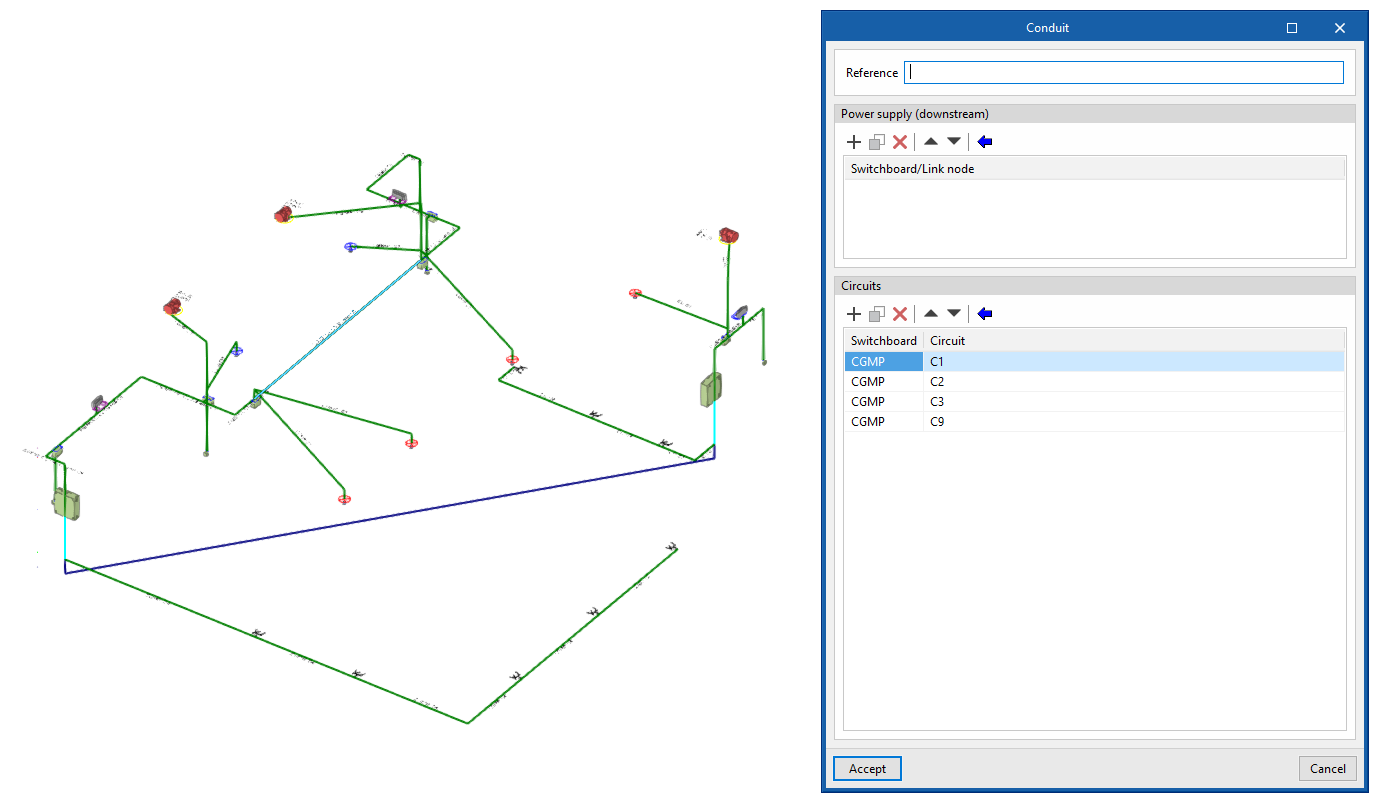
Conduits
Enters conduits in the model after specifying the following parameters:
- Reference
- Power supply (downstream)
- Switchboard/Link node
- Circuits
- Switchboard/Circuit
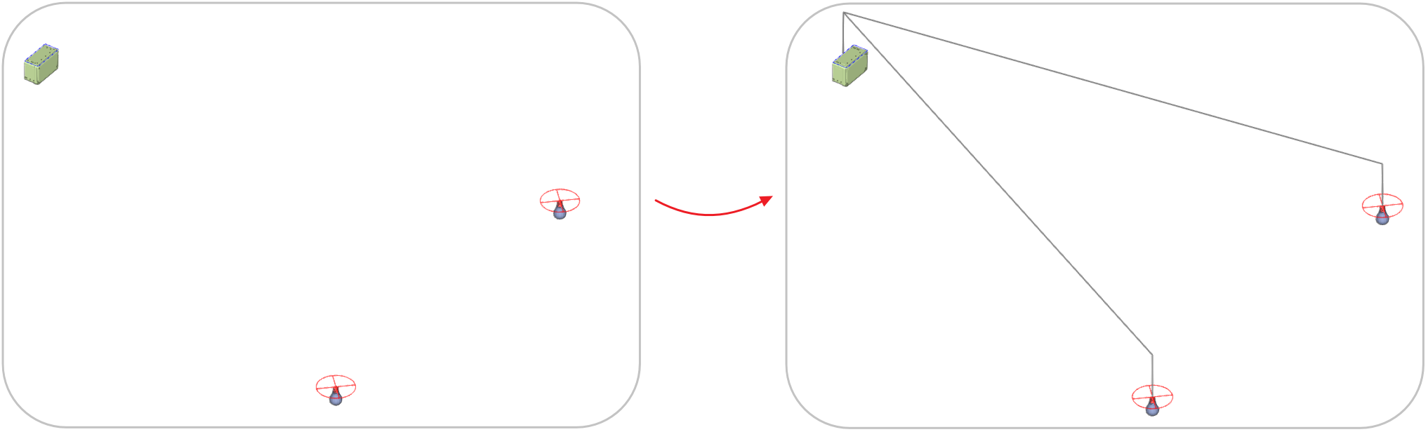
Generate branches
Generates the path of the conduits connecting a junction box to the selected receivers.
Generate conductors
This generates the information on the circuits inside the conduits and the switchboards or link nodes they feed according to the distribution entered graphically in the model, replacing all the previously assigned conductors.
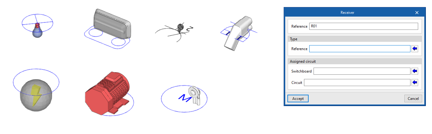
Receivers
Enter receivers freely in the model after specifying the following parameters:
- Reference
- Type
- Type reference
- Assigned circuit
- Switchboard
- Circuit
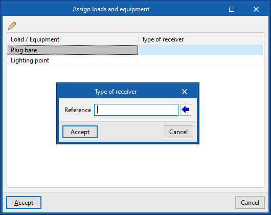
Assign receivers
Automatically assigns receivers to the loads and equipment read from the BIM project according to the specifications indicated. It displays a table where a "Type of receiver" can be associated with each "Load/Equipment".
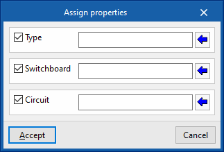
Assign properties
Assigns the following properties to the selected receivers:
- Type
- Switchboard
- Circuit
This option allows mass modification of the properties of the desired receivers without the need to edit them one by one.
Sequence of entering elements
The elements in the installation can be defined in the following sequence:
- Receiver layout
The receivers are placed in the "Work area" in two ways:- Entering them freely via the "Receiver" option.
- Using the tool to "Assign receivers" to the loads and equipment read from the BIM project.
- Switchboard layout
When creating the "Switchboards" for the installation, the electrical "Circuits" that feed each of the receivers are defined, in addition to the "Power supply (upstream)", either another switchboard or an installation link node. - Assigning properties to receivers
After creating the panels and circuits, they are assigned to the receivers by editing them or via the "Assign properties" tool. - Entering conduits
When the "Conduits" are entered, the element they feed is defined, in the case of switchboards or link nodes, and the "Circuits" located in them. Then, they are drawn by connecting the different elements. - Entering junction boxes and pattress boxes (optional)
The distribution can be detailed by entering "Junction boxes" and "Pattress boxes", which can be linked to the rest of the installation by means of "Conduits". - Generating branches and conductors (optional)
As additional tools, the program has several automatic features:- "Generate branches": generates the path of conduits between a junction box and the selected receivers.
- "Generate conductors": identifies and generates the circuits inside each conduit, and the switchboards or link nodes that it feeds, depending on the distribution entered.
- Entering the feeder (optional)
The model can be completed by entering the feeder. To do so:- The layout of the "Link nodes", such as protection boxes and meter centralisation, is indicated.
- These elements are then connected to each other and the switchboards using "Conduits".