Inserting elements
In the "Project" tab, under the "Elements" section of the main toolbar, you can define and enter the following elements:

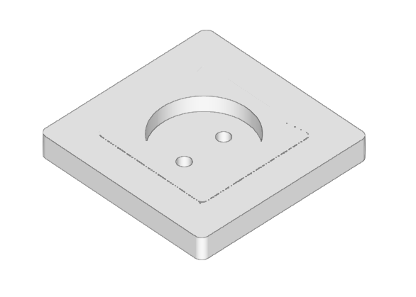
When you add installation elements to the model, they are displayed with their actual dimensions, symbols and reference labels. You can add elements to any view of the model, whether 3D or 2D, such as floor plans or elevations. The elements added to the model will appear in the tables accessible via the "Added elements" option in the "Project" section.
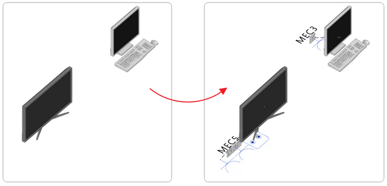
Generate outlets
The program automatically generates an assignment of the necessary power and antenna outlets for equipment imported from the BIM model, in accordance with the settings specified under "Processing of the equipment of the BIM model" within the "General options" section of the "Project" group.
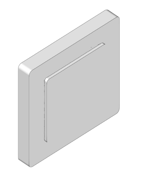
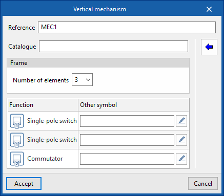
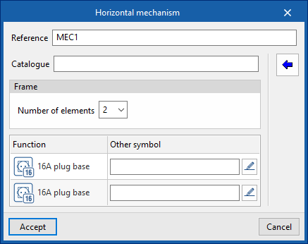
Vertical mechanism / Horizontal mechanism
Inserts an electrical mechanism into the model in a vertical or horizontal position, respectively. This requires the following parameters to be defined:
- Reference
- Catalogue
The "Select from catalogue" button on the right allows you to import items from manufacturer catalogues that have been previously downloaded via the "Catalogues" option in the "Project" section. - Frame
- Number of elements (1, 2, 3, 4, 5)
- Reference (if you used the "Select from catalogue" option)
- Configuration of each element:
- Function
Defines the function of the element. - Another symbol
Selects and uses a specific symbol that has been previously defined in the "Special symbols" tab, within the "Symbols for drawings" section, which can be accessed via the "General options" in the "Project" group.
- Function
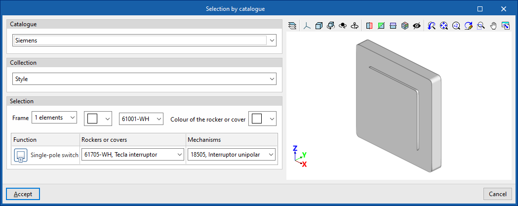
Select from the catalogue
When selecting a mechanism from the catalogue, you must specify the following parameters:
- Catalogue
- Collection
- Selection
- Frame (number of elements, frame colour, reference number, key or cover colour)
- Function
- Rockers and covers
- Mechanisms
- Frame (number of elements, frame colour, reference number, key or cover colour)
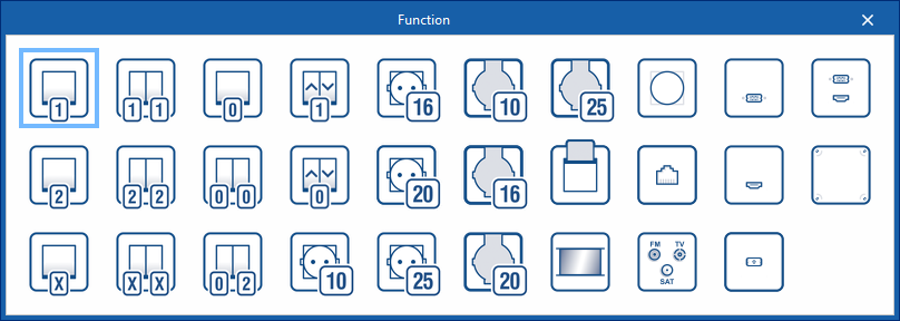
Function selection
The functions available for each element are as follows:
- Single-pole switch
- Switch
- Crossroads
- Double single-pole switch
- Double switch
- Double cross-breeding
- Push button
- Double push-button
- Push-button switch
- Roller shutter switch
- Roller shutter button
- 10A socket outlet
- 16A socket
- 20A socket outlet
- 25A socket outlet
- 10A waterproof socket
- 16A waterproof socket
- 20A waterproof socket
- 25A waterproof socket
- Card switch
- Motion detector
- Dimmer switch
- Telephone socket
- Satellite, TV, FM
- USB
- HDMI
- Optical fibre
- USB to HDMI
- Empty box
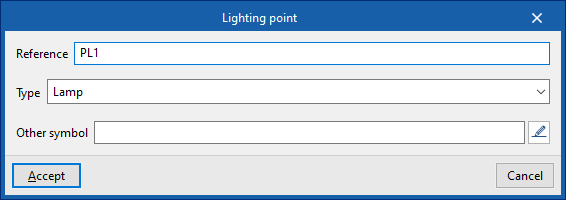
Lighting point
Adds a lighting point to the model. It requires the following parameters to be defined:
- Reference
- Type
- Lamp
- Ceiling spotlight
- Wall-mounted spotlight
- Socket for an incandescent, mercury vapour or similar lamp, either wall-mounted or suspended from the ceiling
- Socket for an incandescent, mercury vapour or similar lamp, either wall-mounted or suspended
- Socket for an incandescent, mercury vapour or similar lamp, recessed into the ceiling
- Socket for an incandescent, mercury vapour or similar lamp, recessed into the wall
- Single-tube fluorescent light
- Two-tube fluorescent light fitting
- Another symbol
Selects and uses a specific symbol that has been previously defined in the "Special symbols" tab, within the "Symbols for drawings" section, which can be accessed via the "General options" in the "Project" group.
Light points can be connected to lighting control units via connecting cables to form lighting circuits.
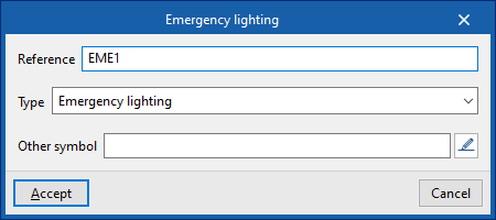
Emergency lighting
Adds an emergency light to the model. It requires the following parameters to be defined:
- Reference
- Type
- Emergency light
- Emergency light (fluorescent)
- Another symbol
Selects and uses a specific symbol that has been previously defined in the "Special symbols" tab, within the "Symbols for drawings" section, which can be accessed via the "General options" in the "Project" group.
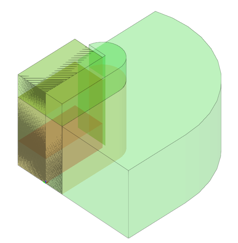
Volume
Enters a protection volume into the model. It requires the following parameters to be defined:
- Reference
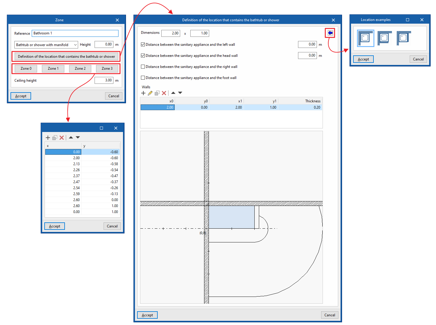
Enters the reference number for the protected volume. - Bathtub or shower with manifold or Shower without manifold
Selects the type of bathroom fixture. - Height
Defines the height of the sanitary fixture (only for "Bathtub or shower with drain"). - Definition of the location that contains the bathtub or shower
- Dimensions (H x W)
Enters the floor plan dimensions of the sanitary fixture. - Site examples
Imports the following site examples:- Bathtub or shower in corner
- Bathtub or shower in corner with fixed wall
- Distance between the sanitary fixture and the wall on the left, at the head end, on the right or at the foot
end
Defines walls at a specific distance from the sanitary fixture on all four sides in plan view. This information is generated automatically if you use the data import function from the "Installation examples" option.
- Walls
Inserts fixed walls in any position by specifying the following parameters. This information is generated automatically if you use the data import function under the "Site examples" option- x0, y0 (start point)
- x1, y1 (end point)
- Thickness
- Dimensions (H x W)
- Volume 0, Volume 1, Volume 2, Volume 3
Allows you to view or edit the ‘x’ and ‘y’ coordinates on the site plan for the specified protection volumes. This information is generated automatically if you use the data import function from the ‘Site Examples’ option. - Ceiling height
Defines the height of the room’s ceiling from the floor.