Introduction
CYPELEC Electrical Mechanisms is a program for the architectural modelling of terminal elements in electrical and telecommunications systems, such as switches, sockets, and audiovisual and telephony connectors.
It can also check the points of use per room and the permitted installation of electrical equipment in bathtub and shower electrical zones.
Workflows supported by the program
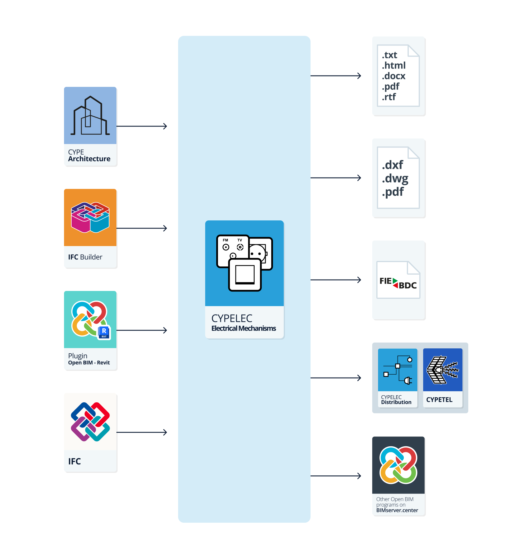
As CYPELEC Electrical Mechanisms is an Open BIM tool and is connected to the BIMserver.center platform, it offers different workflow options.
Data entry
Free modelling / with templates
- Defining the elements in the system by entering them freely in CYPELEC Electrical Mechanisms.
- Defining the elements in the system in CYPELEC Electrical Mechanisms based on DXF/DWG, DWF templates or images (.jpeg, .jpg, .bmp, .wmf).
Importing BIM models
If the CYPELEC Electrical Mechanisms project is linked to a BIM project on the BIMserver.center platform, the following actions can be carried out:
- Importing the model with the building geometry. This allows users to generate the building’s floor plan and to enter the system’s elements based on this geometry:
- Importing models designed in CYPE Architecture.
- Importing models designed in IFC Builder.
- Importing models in IFC format with IFC Uploader (generated by CAD/BIM programs such as Allplan, Archicad and others).
- Importación de modelos diseñados en Autodesk Revit con el Plugin Open BIM - Revit.
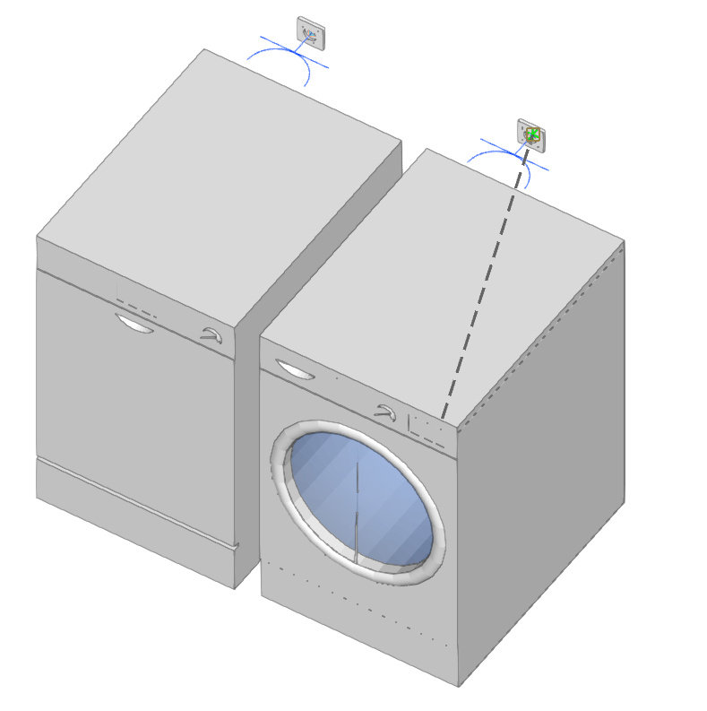
- Importing the position of home appliances to be used in the automatic electrical outlet generation process in CYPELEC Electrical Mechanisms:
- Importing home appliance models from CYPE Architecture.
- Importing the geometry of the sanitary appliances to be used in the process of automatic generation of electrical zones in CYPELEC Electrical Mechanisms:
- Importing sanitary appliance models from CYPE Architecture.
Salida de datos
- Exporting drawings to DXF, DWG and PDF formats.
- Exporting the bill of quantities to FIEBDC-3 format.
- Exporting the information generated with CYPELEC Electrical Mechanisms to the BIMserver.center platform using IFC and GLTF formats. This can be viewed by authorised project participants. The information generated by CYPELEC Electrical Mechanisms can be used by the following programs:
- CYPELEC Distribution
Modelling the circuit and load distribution of the system. - CYPETEL Systems
Designing telecommunications systems in buildings.
- CYPELEC Distribution
Work environment
The CYPELEC Electrical Mechanisms interface has two tabs with different work environments: "Project" and "Bill of quantities". Both environments are similar to those in other CYPE programs and have a system of dockable windows that can be customised to adapt the workspace to the project's needs.

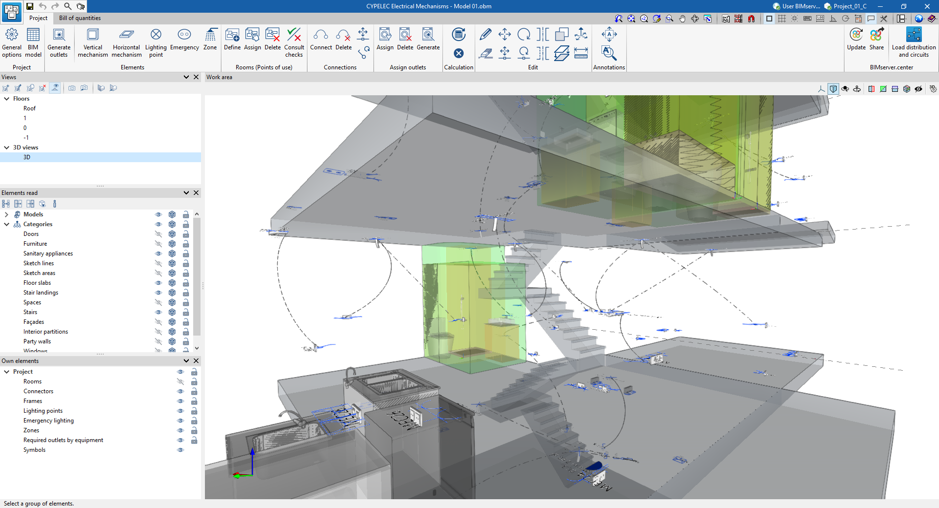
"Project" tab
When starting, the tab activated by default is the "Project" tab. This tab presents a work environment that allows the system design to be carried out quickly and easily, both in a 3D view and in any type of 2D view (such as floor plans and elevations). This way, the elements can be entered into the system using the most appropriate view at any given time.
The "Project" tab displays the following:
- a top toolbar where users will find the tools to manage the project options, enter and edit the elements in the system, rooms and connections, and carry out the analysis and checking of the system;
- the modelling area on the right-hand side of the screen, where all the elements of the project are entered, edited and displayed;
- and, on the left-hand side, several panels with tools for defining the project views and managing the visibility of the elements read from the BIM model and the own elements entered in CYPELEC Electrical Mechanisms.
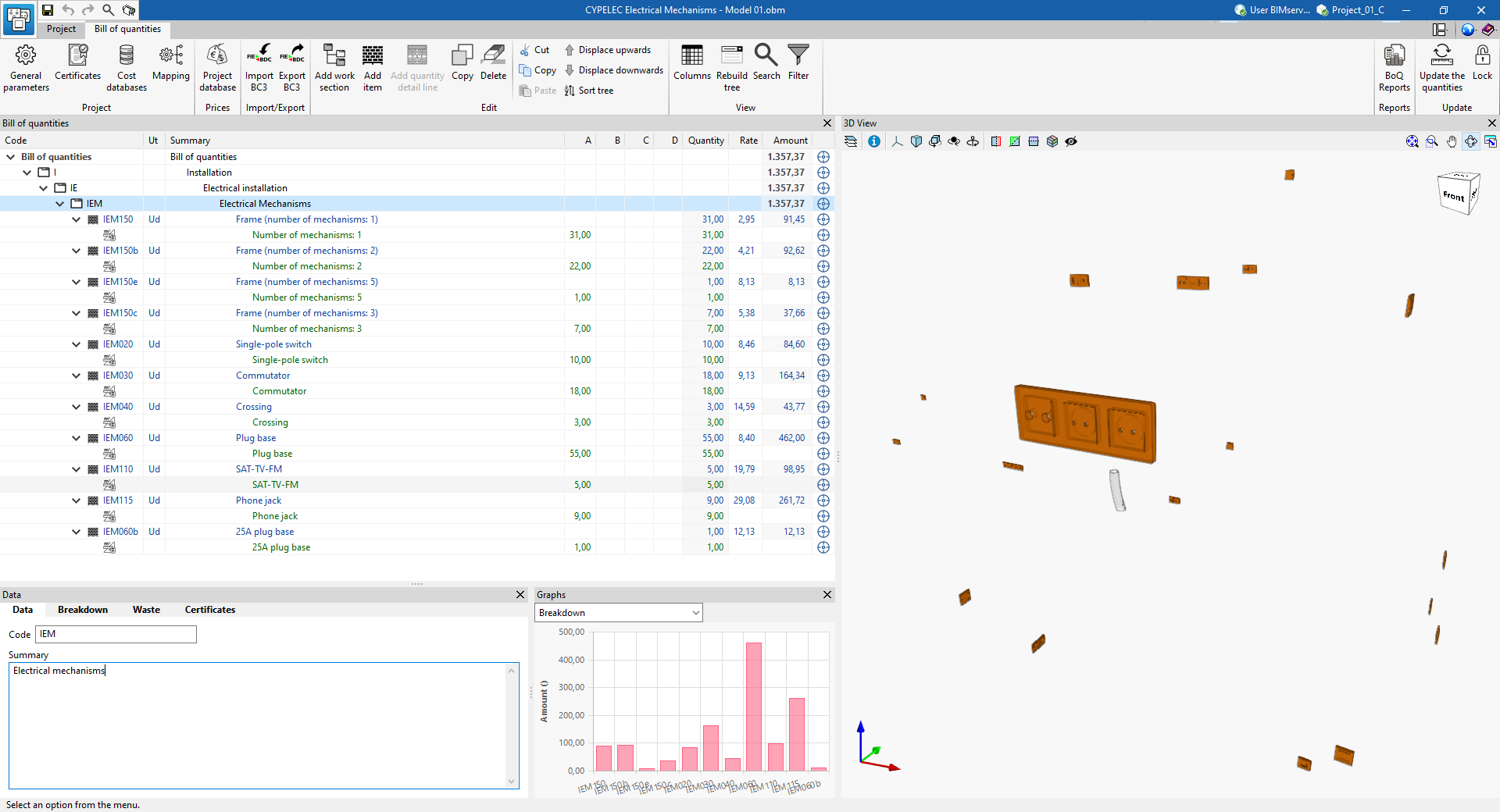
"Bill of quantities" tab
On the other hand, the "Bill of quantities" tab allows users to manage the bill of quantities of the elements in the system that have been entered, and includes the following:
- a top toolbar where the tools for creating and editing the bill of quantities are located, as well as the tools for managing and creating reports;
- a graphic window with its own toolbar, located on the right-hand side, where the different elements in the job can be displayed;
- and a specific area for structuring the bill of quantities, on the left-hand side.
Data input and output sequence for modelling terminal elements of electrical and telecommunication installations
The terminal elements of the electrical and telecommunication installations can be modelled in the program using the following input and output sequence:
- Creating a new job (from "File", "New").
- (Optional) Linking to BIMserver.centre and, in the import wizard, defining codes, importing catalogues and reading and classifying spaces read from the BIM model.
- (Optional) Revising and configuring general options (from "Project, "General options").
- (Optional) Revising and configuring manufacturers' catalogues (from "Project", "Catalogues").
- Placing of terminal elements of the electrical and telecommunication installations in the work area. This can be done in two ways:
- Generating the outlets automatically from the equipment (such as electrical appliances and television sets) read from the BIM model ("Elements" group, "Generate outlets" option).
- Entering the terminal elements manually ( other options in the "Elements" group: mechanisms, light points, emergency, etc.).
- (Optional) Defining and placing the protection volumes (from "Elements", "Volume").
- (Optional) If the rooms have not been read and classified from the spaces of the BIM model in the import wizard, the rooms must be defined and assigned manually ("Rooms (Point of use)" group, "Define" and "Assign" options).
- (Optional) Managing the assignment of outlets to the elements of the BIM model. This can be done in several ways:
- If the automatic generation of outlets ("Elements", "Generate outlets") has been used, the assignment will have already been done automatically.
- For manually entered elements, you can either perform a manual assignment ("Assign outlets", "Assign") or generate the outlet assignment ("Assign outlets", "Assign").
- Entering connections between the terminal elements and mechanisms entered (from "Connections", "Connect").
- Analysing and checking the model ("Analysis" group).
- (Optional) Consulting checks on the spaces ("Rooms" group (Use points), "Consult checks" option).
- (Optional) Managing and generating the bill of quantities ("Bill of quantities" tab).
- Obtaining reports and drawings (from "File", "Reports/Drawings").
- Exporting to BIMserver.center (from "BIMserver.center", "Share").
Creating a new job, linking to a project and importing data
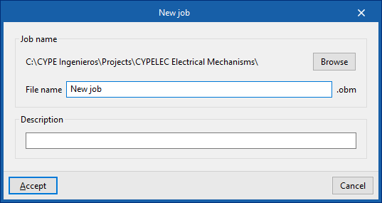
When you launch the app and click on “New”, you are given the option to create a "New project". After entering the "File name" and "Description", the project can then be added to an existing project on BIMserver.center.
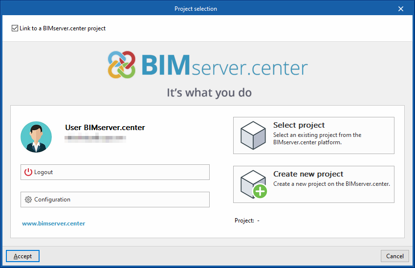
This is done in the "Project selection" window, which offers the following options:
- On the left-hand side, you can sign in using a BIMserver.center account.
- On the right, use the "Select project" option to choose an existing project. You also have the option to "Create a new project". In that case, the project you create will be visible on BIMserver.center from that point onwards.
- You have the option to start the project without linking it to the BIMserver.center platform. To do this, simply uncheck the box labelled "Link to a BIMserver.center project", which is located in the top-left corner.
Once the new project has been created, you will be taken to the program’s main interface, after going through the import wizard, if applicable. At any point thereafter, whilst working on the project, you can share or import project files via the “BIMserver.center” panel, located in the top-right-hand corner of the main interface.
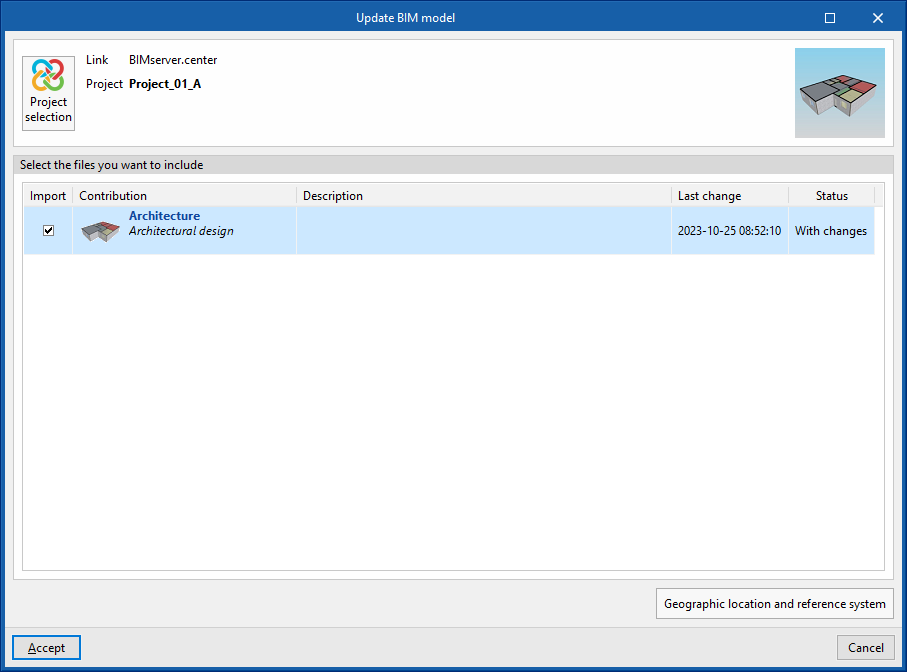
Importing BIM models
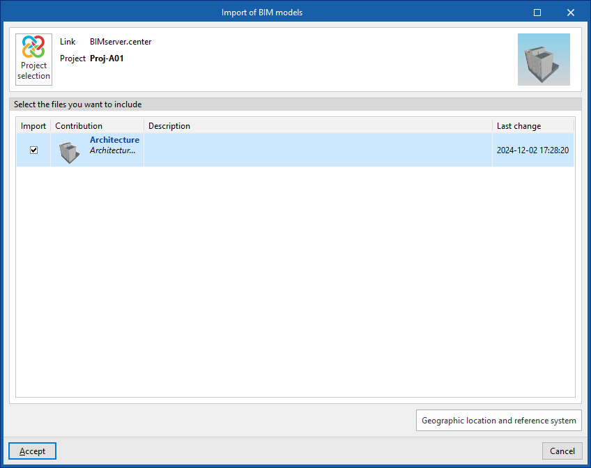
When creating a new project and selecting a project hosted on the BIMserver.center platform via "Select project", the "Import BIM models" window appears, displaying the files contained in that project in IFC format.
The app allows you to include one or more of the existing models in that project. To do this, tick the "Import" box and confirm.
When you access the interface, the graphical window will display the imported models. Furthermore, if this information is available, the floor plans required for developing the plant model will be imported and created.
Setup assistant: selecting codes, downloading catalogues and classifying venues
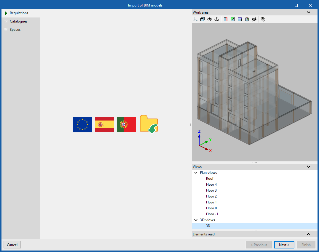
The program then opens the "Import BIM models" wizard, which consists of the following steps:
- In the first step, you can select the applicable codes from those available for different countries and regions, or from a file containing this information that has been previously saved to disk. This automatically imports the checks defined in the regulations or in the file.
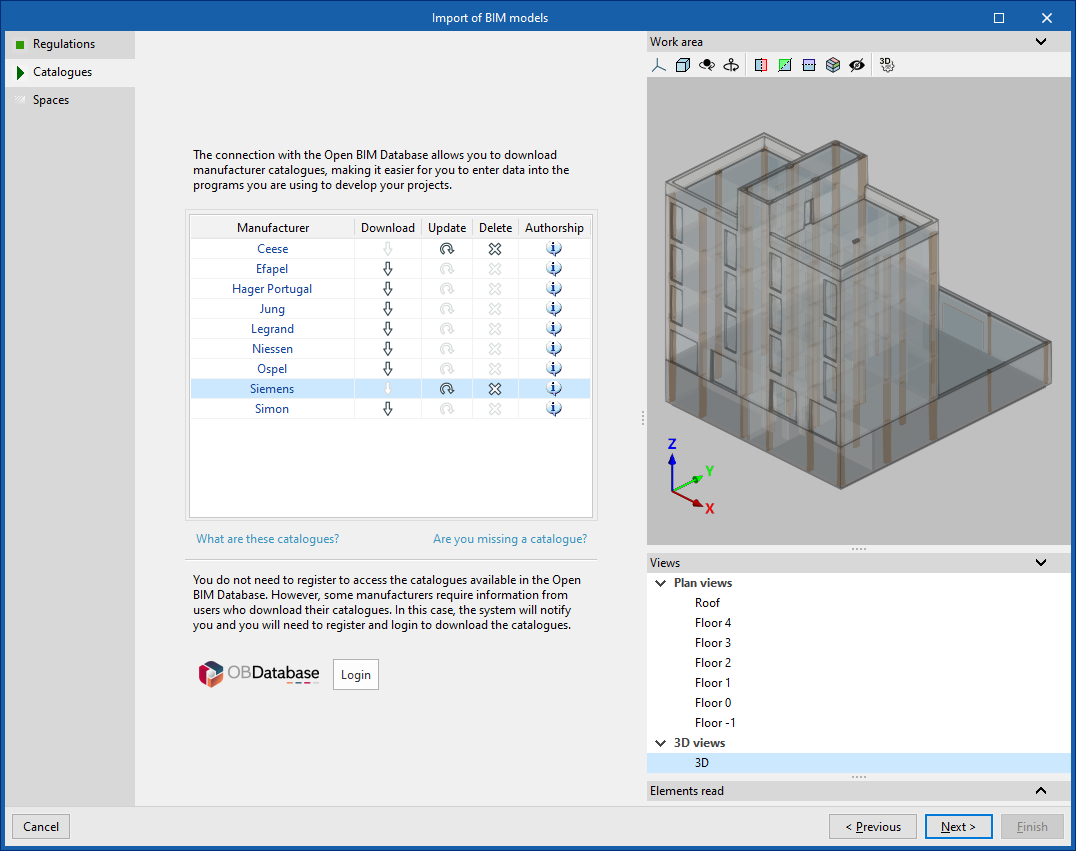
- In the next step, you can establish a connection to the Open BIM Database to download and manage manufacturer catalogues. These catalogues will be available when you add installation elements.
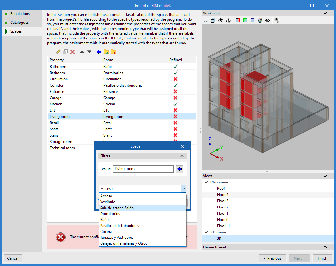
- Finally, in the last step, you can set up the automatic classification of the spaces read from the project’s IFC file according to the specific room types required by the program.
To do this, you must add entries to the assignment table. For each entry, the spaces to be classified are filtered by specifying their property values; by editing these, you can select the room type specific to the program that you wish to assign to them.
It is also possible to use the wizard in the top toolbar to import all spaces read from the IFC file in bulk based on the desired property, thereby generating an entry in the table for each group of spaces with the same property.
On the right, the program allows you to view the layout of the selected spaces in the model.
Spaces that are not to be calculated must be removed from this classification table.
The program will assign the selected room type to all areas read from the IFC file that have the value indicated in the displayed property and will generate their geometry; it will then incorporate them into the model view.
It is necessary to assign a type to all elements in the list. To do this, the program displays the "Defined" column, where spaces filtered by a specific "Property" that have been assigned a "Room" type are marked in green, and those that have not yet been assigned a type are marked in red.
The imported models will then be displayed in the workspace, along with the rooms assigned to the spaces that have been scanned and categorised, where applicable.
Defining the project characteristics
In the "Project" tab, in the "Project" group of the main toolbar, the following project data can be defined:

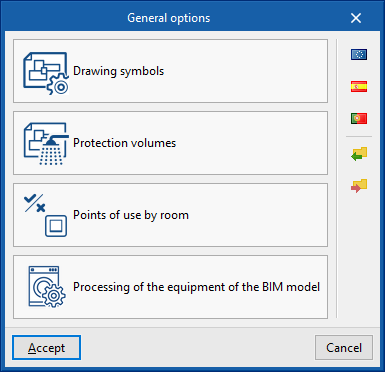
General options
Allows users to define the general options of the system or to import them from the following standard specifications:
Options
- Drawing symbols
- Electrical zones
- Points of use by room
- Processing of the equipment of the BIM model
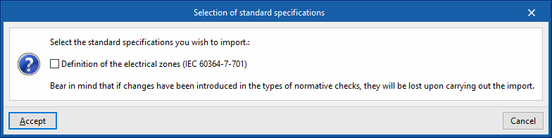
Selection of standard specifications
- Europe
- Definition of the electrical zones (IEC 60364-7-701)
- Spain
- Definition of the electrical zones (IEC 60364-7-701)
- Points of use in home indoor installations (REBT, ITC-BT-25)
- Portugal
- Definition of the electrical zones (RTIEBT, parte 7 / Seccão 701)
- Points of use in home indoor installations
Details of the above-mentioned facilities are given below.
Drawing symbols
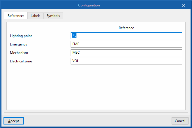
The "Configuration" window is used to define the symbols to be used in the system drawings. It has three tabs:
- References
Allows users to configure the reference text of the following elements:- Lighting point
- Emergency
- Mechanism
- Electrical zone
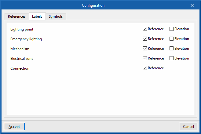
- Labels
Activates or deactivates the information that appears in the element labels:- Lighting point (reference, elevation)
- Emergency lighting (reference, elevation)
- Mechanism (reference, elevation)
- Electrical zone (reference, elevation)
- Connection (reference)
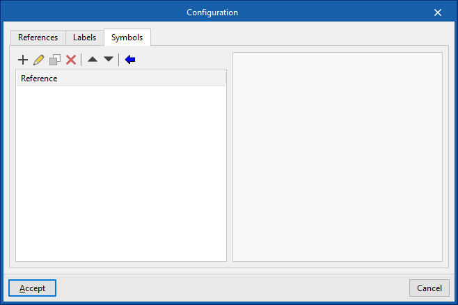
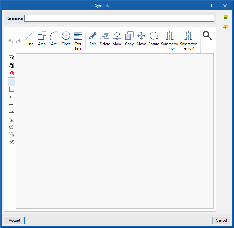
- Symbols
Allows the elements' symbols to be designed manually or to be imported from files on disk:- Designing symbols using lines, areas, arcs, circles and text boxes.
- Importing symbols from DXF/DWG and DWF files
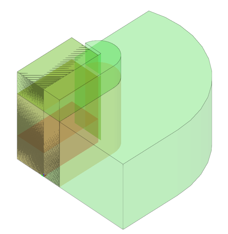
Electrical zones
- Checks on electrical zones (optional)
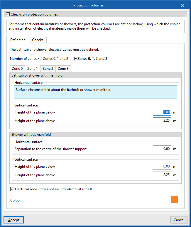
Allows users to activate and detail the checks carried out by the program on the electrical zones, as well as the number of zones to be considered and the geometry of the surfaces surrounding them.
It features the following tabs: - Definition
Defines the number and geometry of the surfaces defining the electrical zones in bathtubs and showers.- Number of zones
Specifies the number of zones to be considered in the project.
- Zone 0, Zone 1, Zone 2 and Zone 3
Defines the geometry of the horizontal and vertical surfaces that surround each of these zones, both for bathtubs or showers with and without manifolds, as well as their colour.
- Number of zones
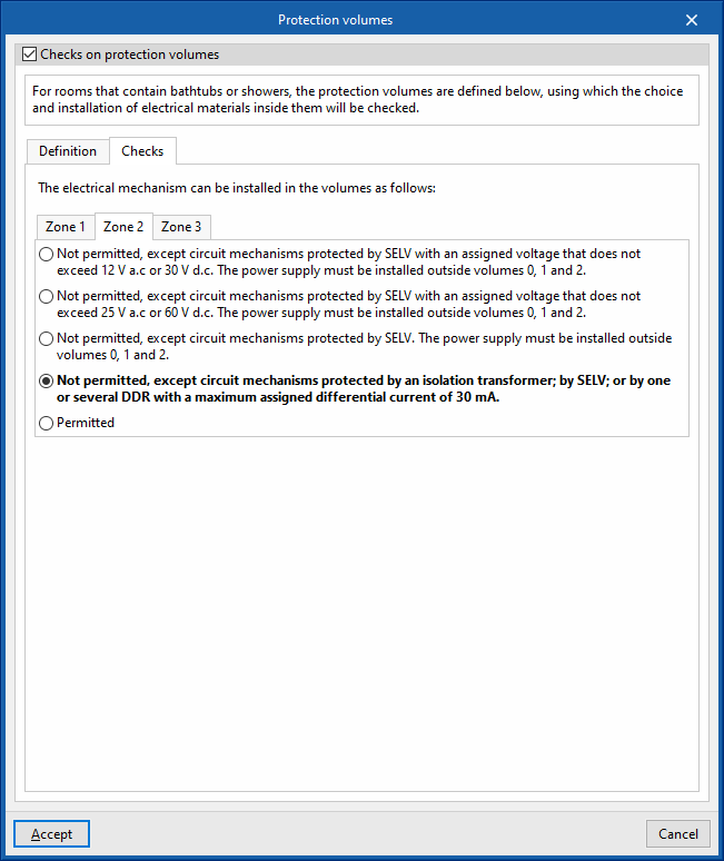
- Checks
Controls whether or not the installation of electrical equipment is permitted in the different electrical zones according to their characteristics.
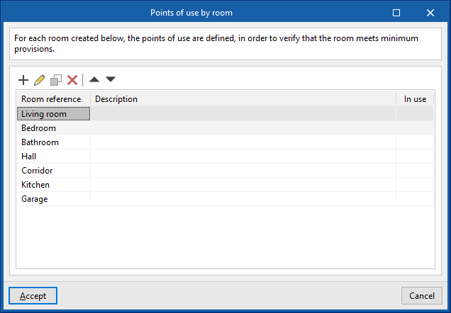
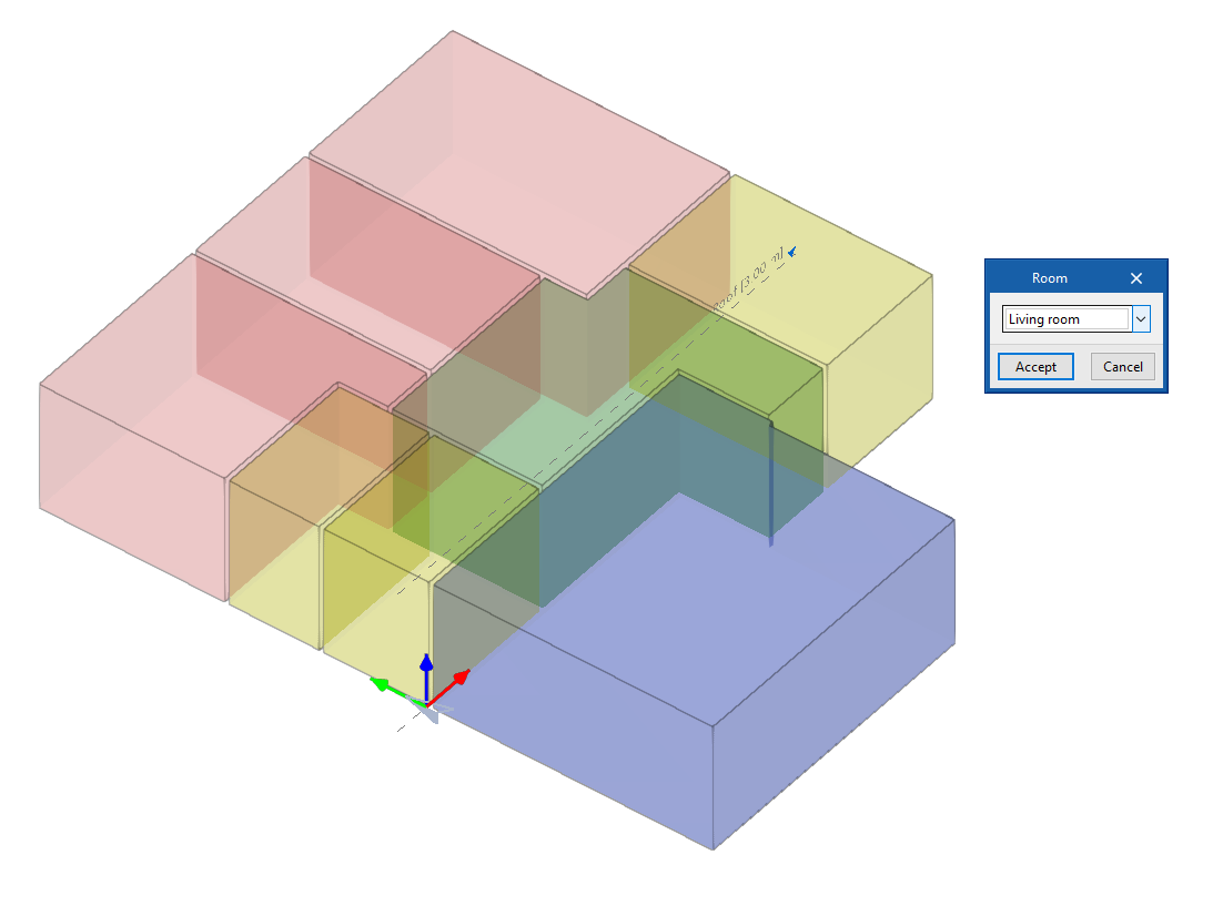
Points of use by room
Allows users to create rooms and define the minimum number of points of use in each of them, to check that the room meets the minimum requirements.
- Room reference
- Description
- Colour
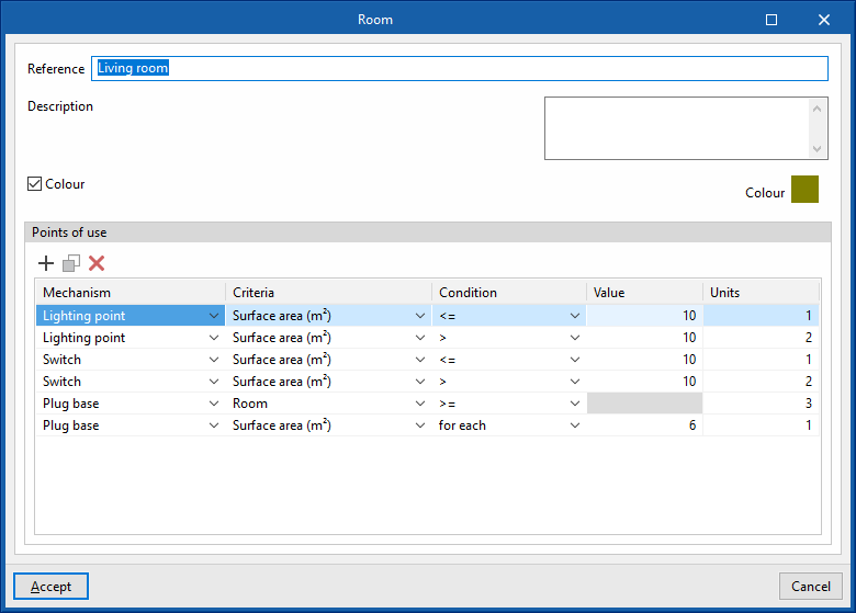
- Points of use
Table defining the minimum number of points of use for each type to be used in the room according to different conditions. The following parameters are indicated in each line:- Mechanism (switch, push button, lighting point, plug base, 25A plug base)
- Criteria
- Condition (>, >=, =, <=, <)
- Value
- Units
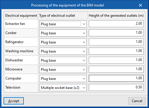
Processing of the equipment of the BIM model
Allows users to set the automatic generation of electrical outlets from the equipment read from the BIM model, which is performed by the program using the "Generate outlets" option from the main toolbar in the "Project" tab.
- Electrical equipment
Extractor fan, cooker, refrigerator, washing machine, dishwasher, microwave, computer and television - Type of electrical outlet
Plug base, 25A plug base, multiple socket base (x2) and multiple socket base (x3) - Height of the generated outlets
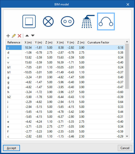
Elements entered
Allows users to consult and modify the data of the elements entered in the model through a series of tables that contain the following information:
- Frames: reference, X, Y, Z, angle
- Lighting points: reference, X, Y, Z, angle
- Emergency lighting: reference, X, Y, Z, angle
- Zones: reference, X, Y, Z, angle
- Connections: reference; X, Y, Z (coordinates of the initial point); X, Y, Z (coordinates of the end point); curvature factor
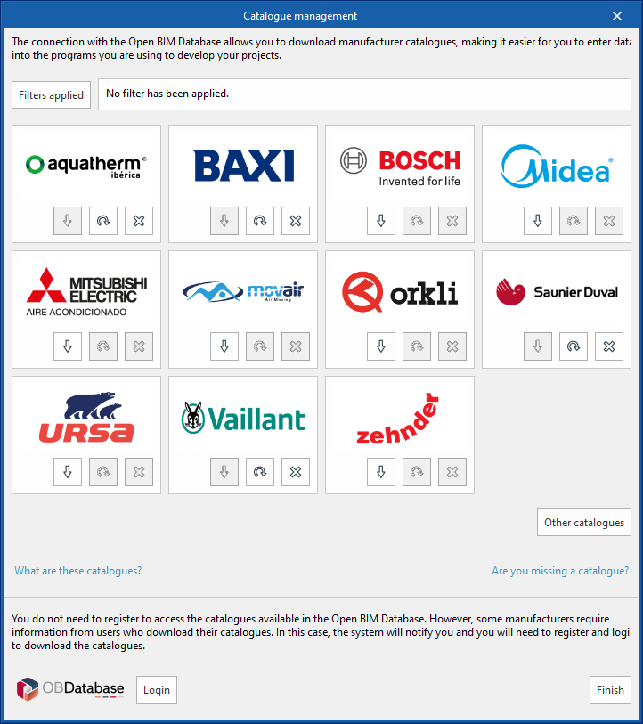
Catalogues
This allows manufacturers' catalogues to be downloaded using the connection to the Open BIM Database, making it easier to enter data into the program for project development.
Clicking on this option opens a window with the available manufacturer catalogues.
Using the "Filters applied" option, filters can be applied by element "Category", "Language" and "Country" so that only manufacturers offering product catalogues with these characteristics are displayed.
Catalogue download
The following options are shown for each manufacturer:
- Download
Downloads the manufacturer's catalogue. The products in the catalogue will be available in the project. - Update
Updates the selected manufacturer's catalogue to the latest version, deleting the version downloaded in the project. - Delete
Deletes the selected manufacturer's catalogue. The products in the catalogue will no longer be available in the project.
Connection to Open BIM Database
At the bottom of this dialogue box, the program allows users to log in with their Open BIM Database account and password.
Inserting elements
In the "Project" tab, under the "Elements" section of the main toolbar, you can define and enter the following elements:

When you add installation elements to the model, they are displayed with their actual dimensions, symbols and reference labels. You can add elements to any view of the model, whether 3D or 2D, such as floor plans or elevations. The elements added to the model will appear in the tables accessible via the "Added elements" option in the "Project" section.
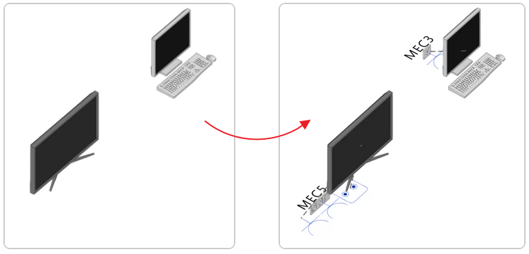
Generate outlets
The program automatically generates an assignment of the necessary power and antenna outlets for equipment imported from the BIM model, in accordance with the settings specified under "Processing of the equipment of the BIM model" within the "General options" section of the "Project" group.
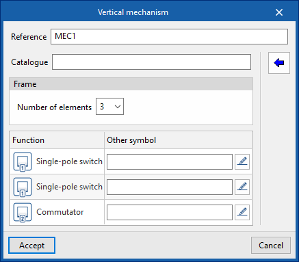
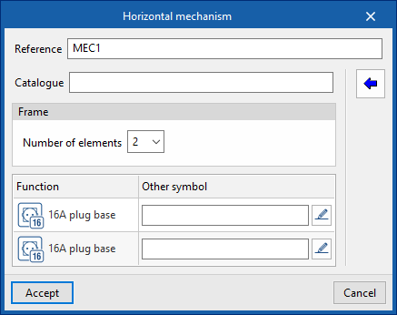
Vertical mechanism / Horizontal mechanism
Inserts an electrical mechanism into the model in a vertical or horizontal position, respectively. This requires the following parameters to be defined:
- Reference
- Catalogue
The "Select from catalogue" button on the right allows you to import items from manufacturer catalogues that have been previously downloaded via the "Catalogues" option in the "Project" section. - Frame
- Number of elements (1, 2, 3, 4, 5)
- Reference (if you used the "Select from catalogue" option)
- Configuration of each element:
- Function
Defines the function of the element. - Another symbol
Selects and uses a specific symbol that has been previously defined in the "Special symbols" tab, within the "Symbols for drawings" section, which can be accessed via the "General options" in the "Project" group.
- Function
Select from the catalogue
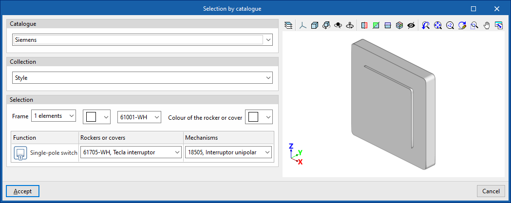
When selecting a mechanism from the catalogue, you must specify the following parameters:
- Catalogue
- Collection
- Selection
- Frame (number of elements, frame colour, reference number, key or cover colour)
- Function
- Rockers and covers
- Mechanisms
- Frame (number of elements, frame colour, reference number, key or cover colour)
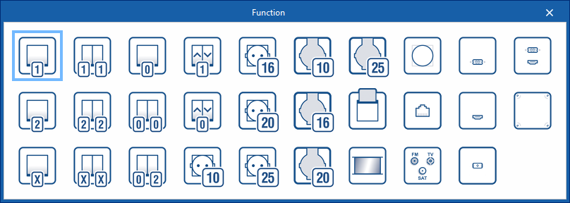
Function selection
The functions available for each element are as follows:
- Single-pole switch
- Switch
- Crossroads
- Double single-pole switch
- Double switch
- Double cross-breeding
- Push button
- Double push-button
- Push-button switch
- Roller shutter switch
- Roller shutter button
- 10A socket outlet
- 16A socket
- 20A socket outlet
- 25A socket outlet
- 10A waterproof socket
- 16A waterproof socket
- 20A waterproof socket
- 25A waterproof socket
- Card switch
- Motion detector
- Dimmer switch
- Telephone socket
- Satellite, TV, FM
- USB
- HDMI
- Optical fibre
- USB to HDMI
- Empty box
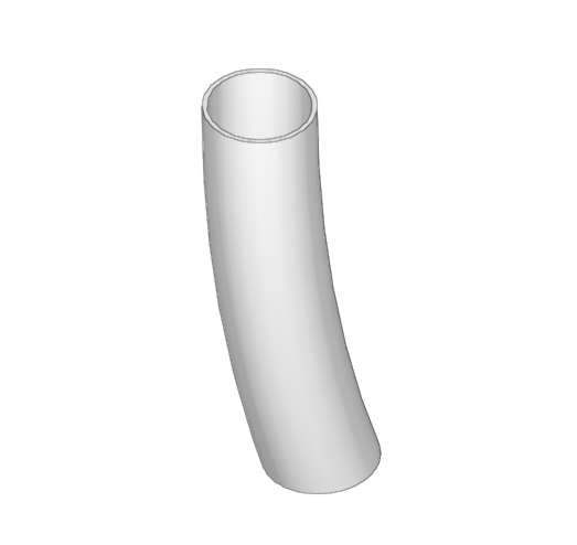
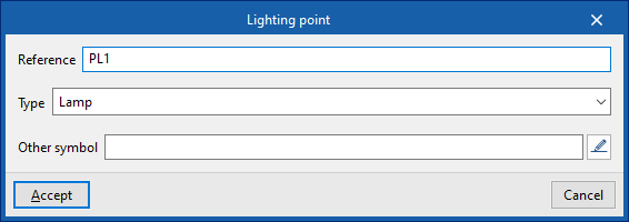
Lighting point
Adds a lighting point to the model. It requires the following parameters to be defined:
- Reference
- Type
- Lamp
- Ceiling spotlight
- Wall-mounted spotlight
- Socket for an incandescent, mercury vapour or similar lamp, either wall-mounted or suspended from the ceiling
- Socket for an incandescent, mercury vapour or similar lamp, either wall-mounted or suspended
- Socket for an incandescent, mercury vapour or similar lamp, recessed into the ceiling
- Socket for an incandescent, mercury vapour or similar lamp, recessed into the wall
- Single-tube fluorescent light
- Two-tube fluorescent light fitting
- Another symbol
Selects and uses a specific symbol that has been previously defined in the "Special symbols" tab, within the "Symbols for drawings" section, which can be accessed via the "General options" in the "Project" group.
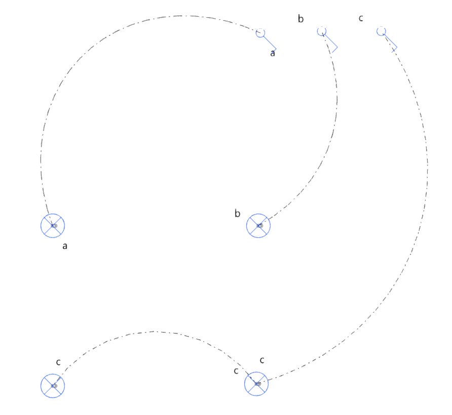
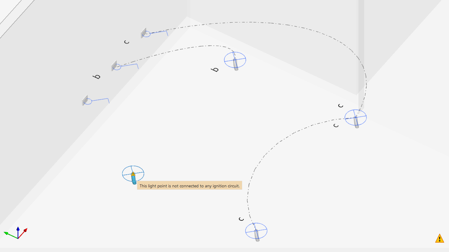
Light points can be connected to lighting control units via connecting cables to form lighting circuits.
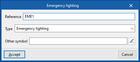
Emergency lighting
Adds an emergency light to the model. It requires the following parameters to be defined:
- Reference
- Type
- Emergency light
- Emergency light (fluorescent)
- Another symbol
Selects and uses a specific symbol that has been previously defined in the "Special symbols" tab, within the "Symbols for drawings" section, which can be accessed via the "General options" in the "Project" group.
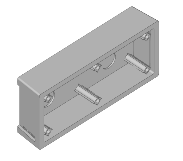
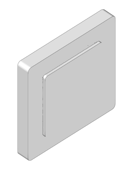
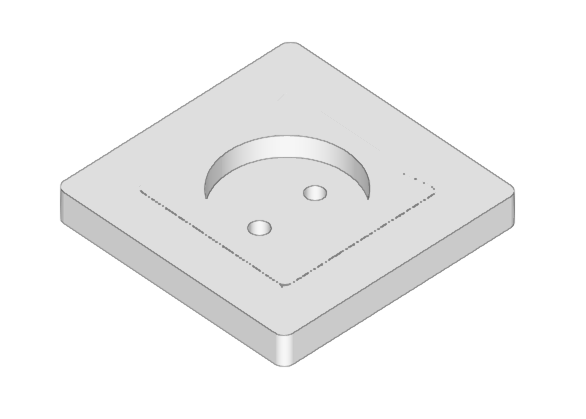
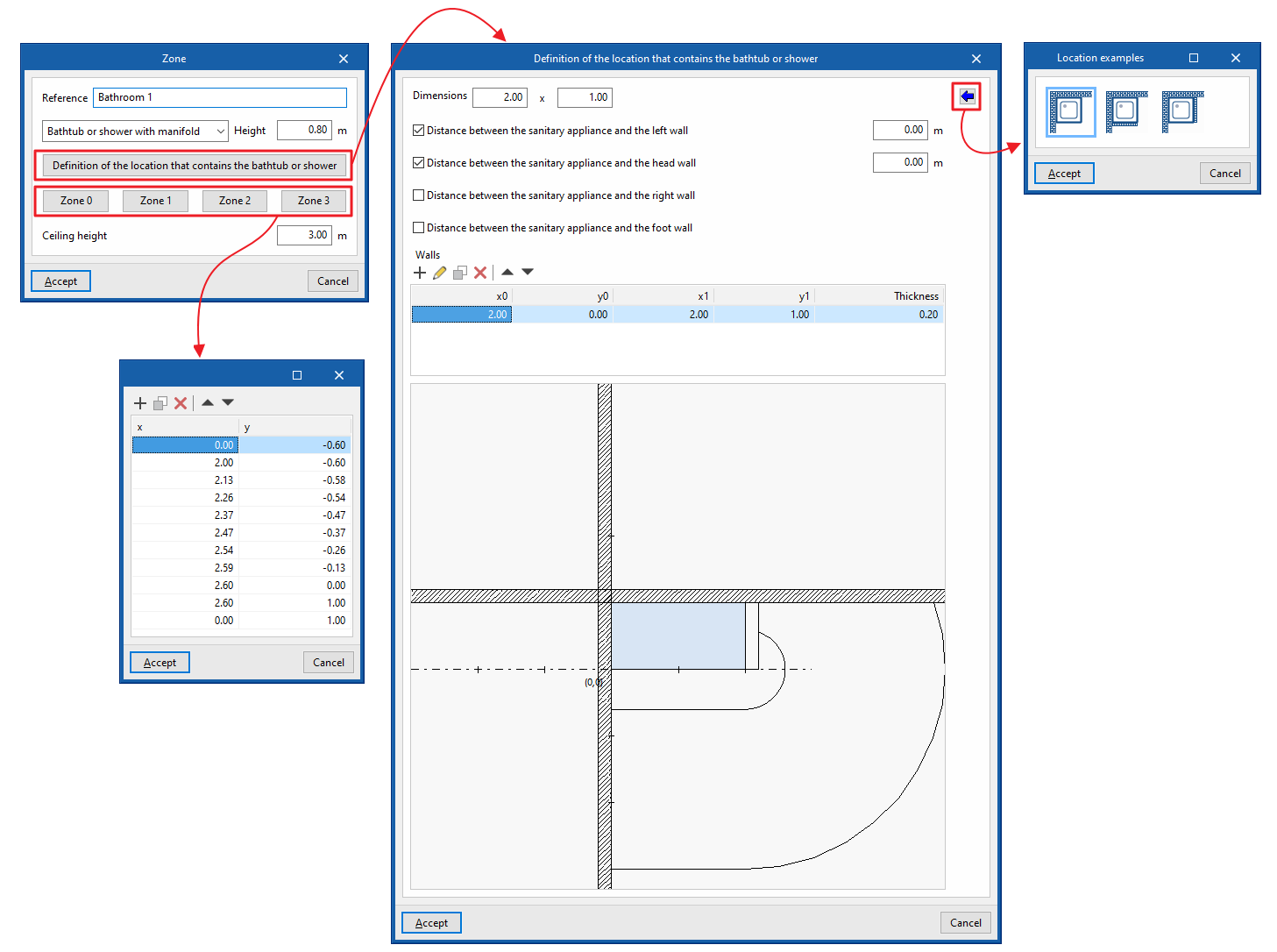
Volume
Enters a protection volume into the model. It requires the following parameters to be defined:
- Reference
Enters the reference number for the protected volume. - Bathtub or shower with manifold or Shower without manifold
Selects the type of bathroom fixture. - Height
Defines the height of the sanitary fixture (only for "Bathtub or shower with drain"). - Definition of the location that contains the bathtub or shower
- Dimensions (H x W)
Enters the floor plan dimensions of the sanitary fixture. - Site examples
Imports the following site examples:- Bathtub or shower in corner
- Bathtub or shower in corner with fixed wall
- Distance between the sanitary fixture and the wall on the left, at the head end, on the right or at the foot
end
Defines walls at a specific distance from the sanitary fixture on all four sides in plan view. This information is generated automatically if you use the data import function from the "Installation examples" option.
- Walls
Inserts fixed walls in any position by specifying the following parameters. This information is generated automatically if you use the data import function under the "Site examples" option- x0, y0 (start point)
- x1, y1 (end point)
- Thickness
- Dimensions (H x W)
- Volume 0, Volume 1, Volume 2, Volume 3
Allows you to view or edit the ‘x’ and ‘y’ coordinates on the site plan for the specified protection volumes. This information is generated automatically if you use the data import function from the ‘Site Examples’ option. - Ceiling height
Defines the height of the room’s ceiling from the floor.
Defining rooms and points of use
Within the "Project" tab, in the "Rooms (Points of use)" group of the main toolbar, the following options can be used:

These options allow the program to perform checks related to the number of points of use in the rooms that make up the building.
Define
Allows users to select a room from those defined in "Points of use by room" under "General options" and assign it to a space from the model read from the BIM project.
Assign
Allows users to modify the assignment of a room to a space by selecting one of the rooms previously defined in the project.
Delete
Allows users to remove the assignment of a room to a space from the model.
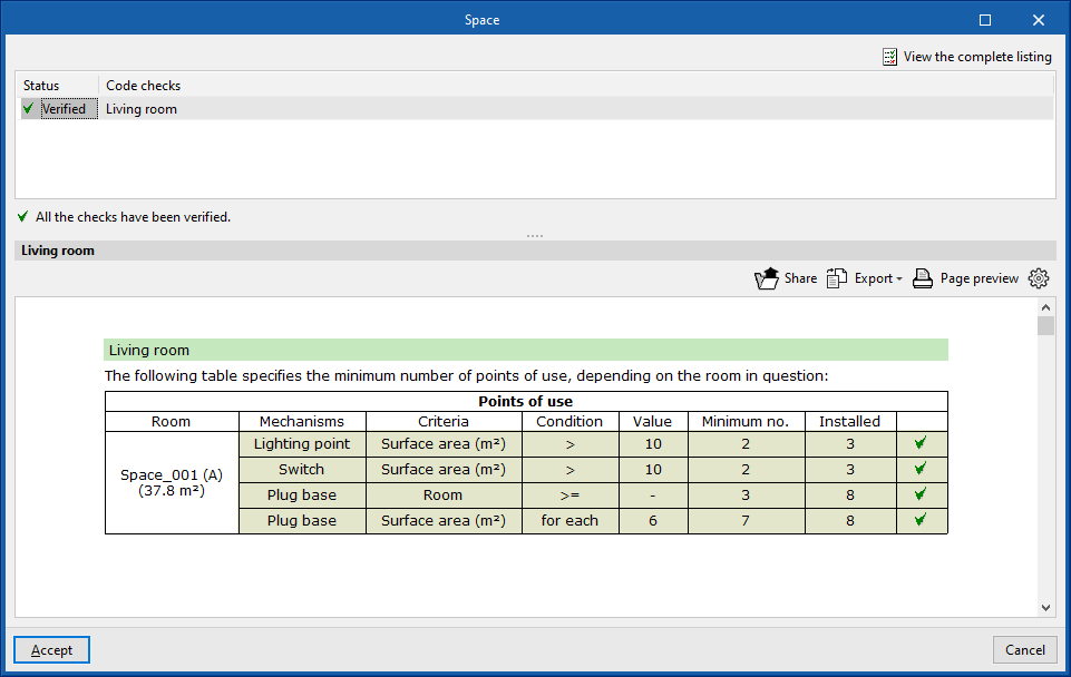
Consult checks
After selecting a room, the program displays the checklist for compliance with the criteria of the points of use defined for that room in a dialogue box.
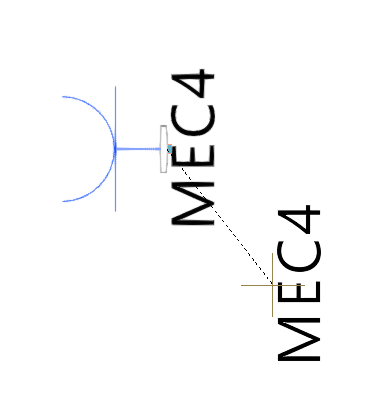
Entering connections
Within the "Project" tab, in the "Connections" group of the main toolbar, the following operations can be carried out:

Connect
Enters connections between two elements of the system, indicating the start point, end point and the curvature of the connection line.
Delete
Deletes one or more previously entered connection line(s).
Move
Moves the start point or end point of a previously entered connection line.
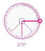
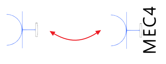
Rotate
Rotates the graphical representation of the electrical mechanisms entered on the plan.
Assigning outlets
When reading a BIM project, CYPELEC Electrical Mechanisms makes it possible to import electrical equipment included in the architectural model. The program will warn users of the need to provide the required service for this equipment. To do this, the following options can be used in the "Project" tab, in the "Assign outlets" group of the main toolbar:

Assign
Manually assigns CYPELEC Electrical Mechanisms electrical outlets or antennas to the devices imported from the BIM model. First, the device is selected and then the outlet is assigned.
Delete
Deletes the assignment of an outlet to the electrical equipment.
Generate
Automatically assigns nearby unused outlets to electrical equipment with unassigned outlets. The program will select the one that best suits the service and proximity of the outlets available.
"Calculation" group in the main toolbar
Within the "Project" tab, in the "Calculation" group of the main toolbar, the following options are available:

Calculation
Checks whether the elements of the installation are correctly entered and whether the parameters that have been entered are within the ranges defined in the calculation options.
Show/Hide incidents
If this option is activated, the elements where an error has occurred will be highlighted. Hovering the mouse cursor over these elements will display the message describing the error.
Editing tools
Within the "Project" tab, in the "Edit" group of the main toolbar, you will find the main tools for editing the model. Some of these tools are common to other CYPE programs.

The main tool area of this group allows the following operations to be carried out:
| Edit | Edits the parametric properties of the selected element in the model. | |
| Delete | Deletes a previously entered element. | |
| Move a group of elements | Moves a group of elements. | |
| Move | Moves an element or a node in an element. | |
| Rotate a group of elements | Rotates a group of elements. | |
| Rotate | Rotates an element about the "x", "y" or "z" axis. | |
| Symmetry (copy) | Copies a selection of elements with symmetry with respect to a vertical plane defined by two points. | |
| Symmetry (move) | Moves a selection of elements with symmetry about a vertical plane defined by two points. | |
| Copy | Creates a copy of one or more elements. | |
| Copy onto another floor plan | Creates a copy of one or more elements on another floor plan. | |
| Modify height position | Modifies the height position of an element by specifying a relative displacement or absolute elevation. | |
| Measure lengths on plan | Measures lengths between defined points on the model. If a closed contour is selected, it also indicates the area. |
Managing annotations
Within the "Project" tab, in the "Annotations" group of the main toolbar, the following options can be found:

Move tag
Moves the element tags of the installation.
Show/Hide tag
Activates or deactivates the visibility of the element tags in the installation.
Results output
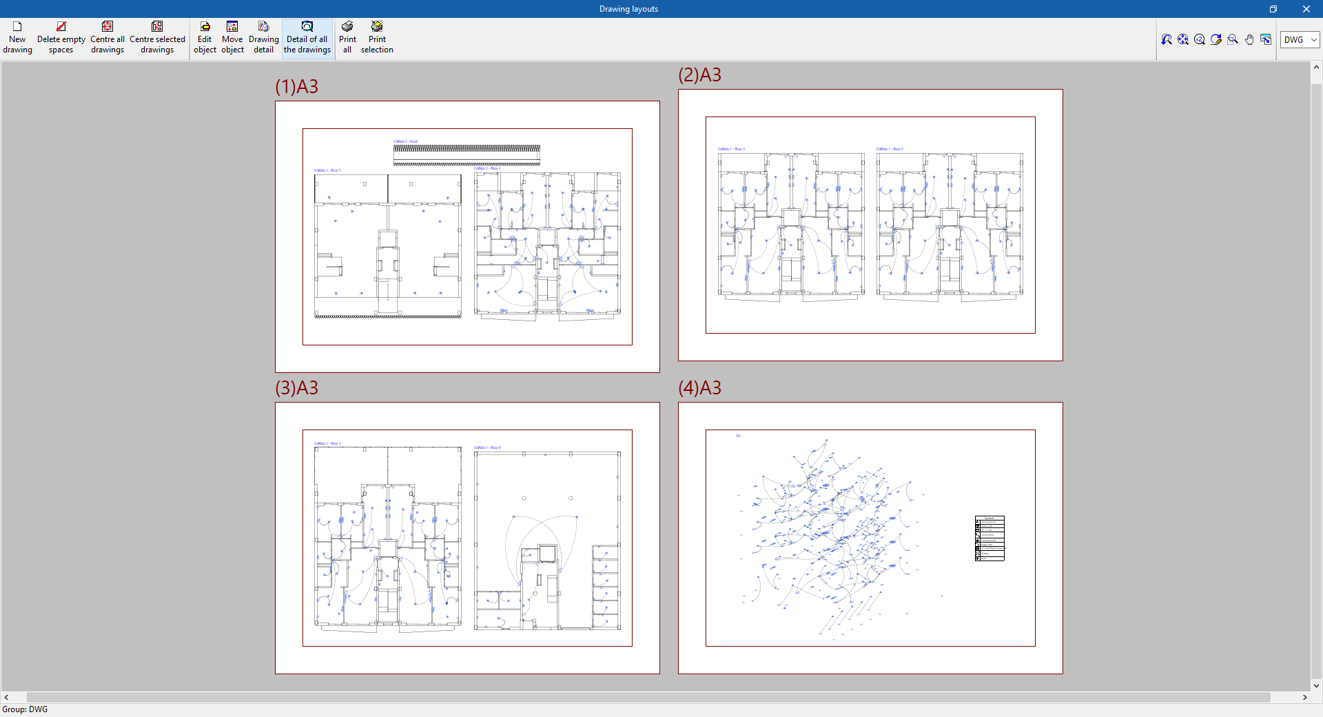
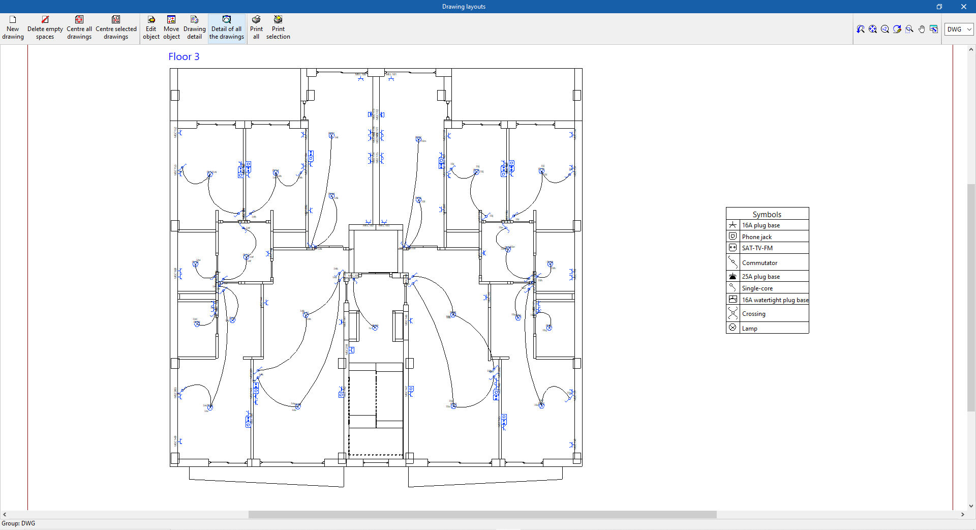
Drawings in DWG, DXF or PDF format
The program allows users to print the drawings of the job on any peripheral device configured on the computer, or to create DWG, DXF or PDF files.
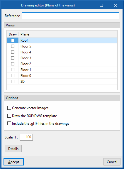
The following options can be configured when editing the drawing:
- Views to be drawn
- Options
- Generate vector images
- Draw the DXF/DWG template
- Include the .glTF files in the drawings
- Scale
Results in the "Bill of quantities" tab
If the work is completed in the "Bill of quantities" tab, CYPELEC Electrical Mechanisms allows the following documents to be obtained:
- Exporting the bill of quantities in FIEBDC-3 format (BC3)
- Bill of quantities reports (in HTML, PDF, TXT, RTF or DOCX format)
IFC and GLTF files supported by BIMserver.center
When the project is exported to the BIMserver.center platform, an IFC file and a 3D model in GLTF format are automatically exported for the integration of the model of the electrical mechanisms, connections and other elements of the system in the Open BIM project, allowing it to be visualised:
- on the online platform;
- in the BIMserver.center app for iOS and Android;
- in virtual reality and augmented reality;
- in other CYPE programs.
Integration into the BIMserver.center platform
Many of CYPE's programs are connected to the BIMserver.center platform and allow collaborative work to be carried out via the exchange of files in formats based on open standards.
Please note that, to work on BIMserver.center, users can register on the platform free of charge and create a profile.
When accessing a program connected to the platform, the program connects to a project in BIMserver.center. This way, the files of the projects that have been developed collaboratively in BIMserver.center are kept up to date.

| More information: |
|---|
| For further details related to using CYPE software via the BIMserver.center platform, please click on this link. |
Options available in CYPELEC Electrical Mechanisms
In the "BIMserver.center" group of the main toolbar, users will find the features needed to use CYPELEC Electrical Mechanisms together with other BIMserver.center tools:

Update
Allows users to update the information in the models previously imported into the project or import new models.
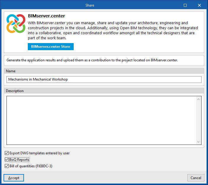
Share
Allows users to export the model information developed with CYPELEC Electrical Mechanisms to BIMserver.center to share with other users, including its three-dimensional representation and the facility system drawings.
During the export process, users can define information related to the identification of the files to be exported and the types of files that are generated:
- Name
- Description
- Export DWG templates entered by the user (optional)
- BoQ reports (optional)
- Bill of quantities (FIEBDC-3) (optional)
Direct connection to other programs
CYPELEC Electrical Mechanisms includes an option for directly connecting to Open BIM tools which allows users to continue their work. With this option, the CYPELEC Electrical Mechanisms BIM model can be sent to the following programs:
- CYPELEC Distribution
This program can import the location of the lighting points and electrical mechanisms from CYPELEC Electrical Mechanisms to carry out the distribution of loads and circuits. - CYPETEL Systems
This program can read the telecommunication mechanisms entered in CYPELEC Electrical Mechanisms and their spatial position for the definition of the necessary outlets.