Defining the project characteristics
In the "Project" tab, in the "Project" group of the main toolbar, the following project data can be defined:

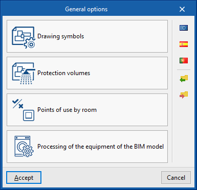
General options
Allows users to define the general options of the system or to import them from the following standard specifications:
Options
- Drawing symbols
- Electrical zones
- Points of use by room
- Processing of the equipment of the BIM model
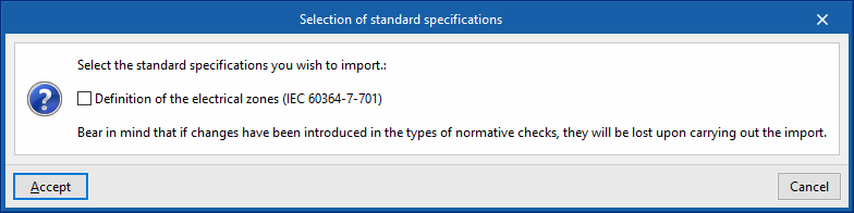
Selection of standard specifications
- Europe
- Definition of the electrical zones (IEC 60364-7-701)
- Spain
- Definition of the electrical zones (IEC 60364-7-701)
- Points of use in home indoor installations (REBT, ITC-BT-25)
- Portugal
- Definition of the electrical zones (RTIEBT, parte 7 / Seccão 701)
- Points of use in home indoor installations
Details of the above-mentioned facilities are given below.
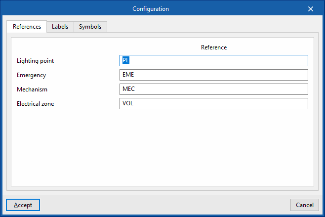
Drawing symbols
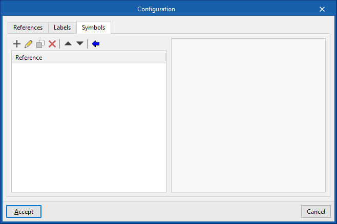
The "Configuration" window is used to define the symbols to be used in the system drawings. It has three tabs:
- References
Allows users to configure the reference text of the following elements:- Lighting point
- Emergency
- Mechanism
- Electrical zone
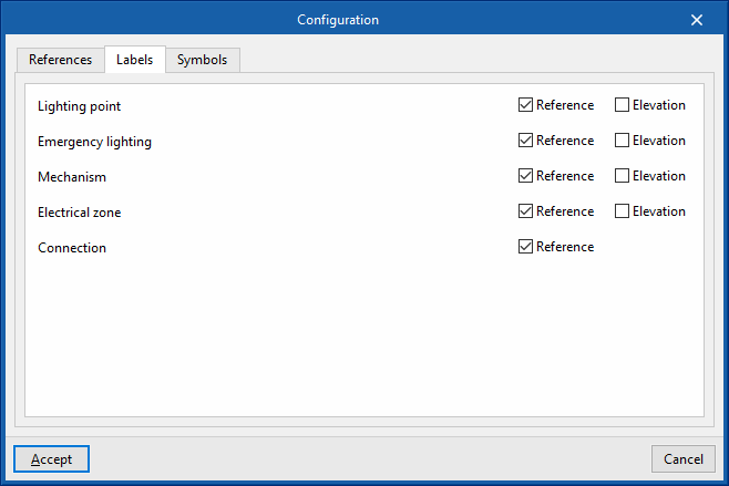
- Labels
Activates or deactivates the information that appears in the element labels:- Lighting point (reference, elevation)
- Emergency lighting (reference, elevation)
- Mechanism (reference, elevation)
- Electrical zone (reference, elevation)
- Connection (reference)
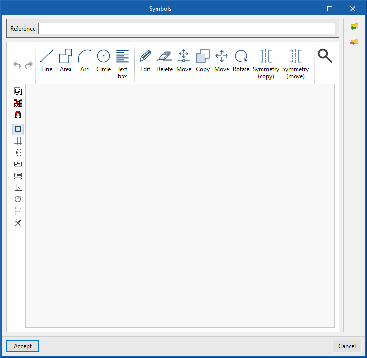
- Symbols
Allows the elements' symbols to be designed manually or to be imported from files on disk:- Designing symbols using lines, areas, arcs, circles and text boxes.
- Importing symbols from DXF/DWG and DWF files
Electrical zones
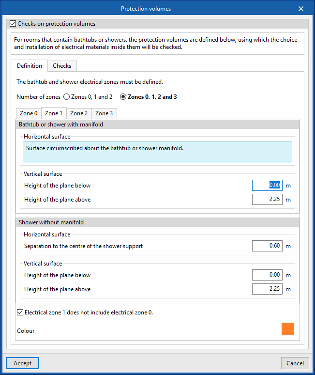
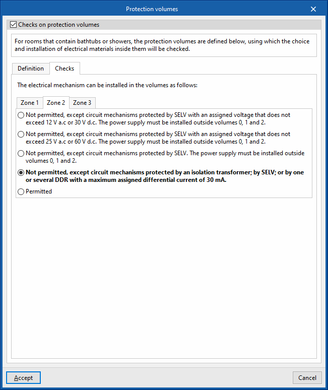
- Checks on electrical zones (optional)
Allows users to activate and detail the checks carried out by the program on the electrical zones, as well as the number of zones to be considered and the geometry of the surfaces surrounding them.
It features the following tabs: - Definition
Defines the number and geometry of the surfaces defining the electrical zones in bathtubs and showers.- Number of zones
Specifies the number of zones to be considered in the project.
- Zone 0, Zone 1, Zone 2 and Zone 3
Defines the geometry of the horizontal and vertical surfaces that surround each of these zones, both for bathtubs or showers with and without manifolds, as well as their colour.
- Number of zones
- Checks
Controls whether or not the installation of electrical equipment is permitted in the different electrical zones according to their characteristics.
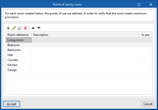
Points of use by room
Allows users to create rooms and define the minimum number of points of use in each of them, to check that the room meets the minimum requirements.
- Room reference
- Description
- Colour
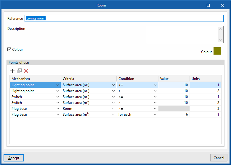
- Points of use
Table defining the minimum number of points of use for each type to be used in the room according to different conditions. The following parameters are indicated in each line:- Mechanism (switch, push button, lighting point, plug base, 25A plug base)
- Criteria
- Condition (>, >=, =, <=, <)
- Value
- Units
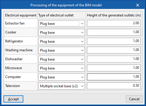
Processing of the equipment of the BIM model
Allows users to set the automatic generation of electrical outlets from the equipment read from the BIM model, which is performed by the program using the "Generate outlets" option from the main toolbar in the "Project" tab.
- Electrical equipment
Extractor fan, cooker, refrigerator, washing machine, dishwasher, microwave, computer and television - Type of electrical outlet
Plug base, 25A plug base, multiple socket base (x2) and multiple socket base (x3) - Height of the generated outlets
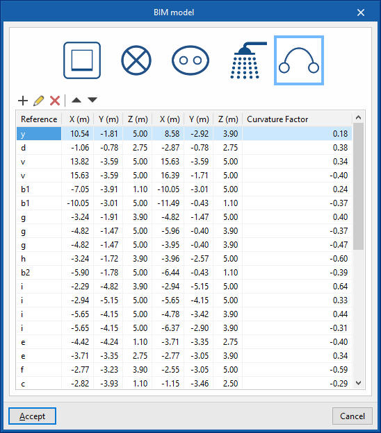
Elements entered
Allows users to consult and modify the data of the elements entered in the model through a series of tables that contain the following information:
- Frames: reference, X, Y, Z, angle
- Lighting points: reference, X, Y, Z, angle
- Emergency lighting: reference, X, Y, Z, angle
- Zones: reference, X, Y, Z, angle
- Connections: reference; X, Y, Z (coordinates of the initial point); X, Y, Z (coordinates of the end point); curvature factor
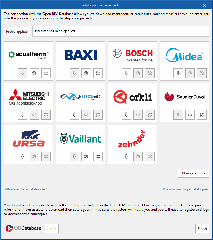
Catalogues
This allows manufacturers' catalogues to be downloaded using the connection to the Open BIM Database, making it easier to enter data into the program for project development.
Clicking on this option opens a window with the available manufacturer catalogues.
Using the "Filters applied" option, filters can be applied by element "Category", "Language" and "Country" so that only manufacturers offering product catalogues with these characteristics are displayed.
Catalogue download
The following options are shown for each manufacturer:
- Download
Downloads the manufacturer's catalogue. The products in the catalogue will be available in the project. - Update
Updates the selected manufacturer's catalogue to the latest version, deleting the version downloaded in the project. - Delete
Deletes the selected manufacturer's catalogue. The products in the catalogue will no longer be available in the project.
Connection to Open BIM Database
At the bottom of this dialogue box, the program allows users to log in with their Open BIM Database account and password.