Entering drainage areas in the water evacuation system
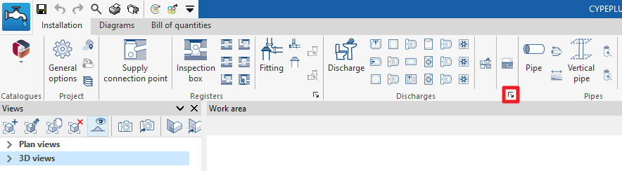
In the "Installation" tab of the "Sanitary Systems" tab, in the "Discharges" group of the main toolbar, there are options for entering the discharges in the evacuation system:

Drainage area
Inserts a drainage area in the water evacuation system, both for wastewater and rainwater.
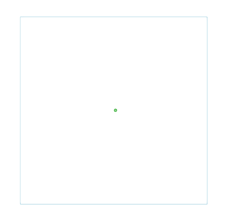
Drainage areas are defined by drawing their polygonal outline in the model. Subsequently, elements such as drains, drainage pipes, gutters or longitudinal drains are entered to collect the flow associated with the projected area of the drainage areas on which they are located. It is also possible to modify the "Rainfall intensity" from the corresponding option in the "Project" group.
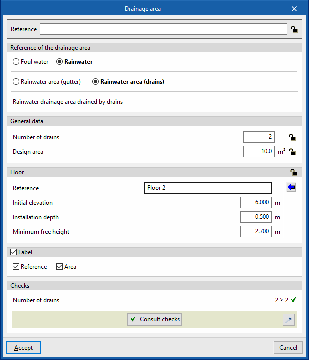
When entering or editing a drainage area, the following parameters can be configured. Some parameters only appear if the "Simplified entry" option, which can be found in the "Design options" of the "General options", is kept deactivated:
- Reference
Element reference. This value can be locked or unlocked. If unlocked, the program will create or modify the reference when updating results. - Discharge reference
Selects the type of discharge by its reference. These types can be created and edited in “Discharges” in the "Design and check options to be carried out" section in the "General options" of the "Project" group. - General data
- Number of drains (Lock/Unlock)
Defines the number of sinks associated with the drainage area. This only appears if the "Check the number of drains in accordance with table values" box in the selected drainage area type is checked. If this value is unlocked, the program can modify it when updating results, taking the data from the drains located in the model over the drainage area. - Design area (Lock/Unlock)
Defines the design area. If this value is unlocked, the program can modify it when updating results, taking the data from the area of the polygonal contour drawn on the model.
- Number of drains (Lock/Unlock)
- Floor (Lock/Unlock)
Defines the floor data assigned to the element. This section only appears when editing a previously entered element. If this section is unlocked, the program can modify this data, which is generated according to the layout of the element in the model. Using the wizard available on the right, the data of a floor plan defined in the "Floor plans" section of the "Project" group can be imported.- Reference
- Initial elevation
- Installation depth
- Minimum free height
- Label (optional)
Manages the information visible in the element's label.- Reference (optional)
- Area (optional)
- Consult checks
Consults and lists the checks carried out on the element, if defined in the selected drainage area type. - Design
This feature, accessed by clicking on the button in the bottom right-hand corner, is used to automatically design the parameters considered in the drainage area editing panel so that they comply with the defined checks.
These options are the same as those available in the section "Design and check options to be carried out", which is accessed from the "General options" of the "Project" group.