Entering drainage areas in the water evacuation system
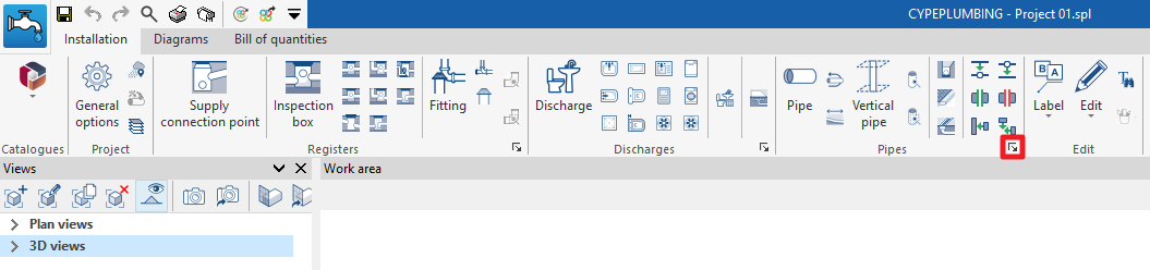
In the "Installation" tab of the "Sanitary Systems" tab, in the "Pipes" group of the main toolbar, there are options for inserting drainage pipes, gutters and longitudinal drains into the drainage system:

The drainage pipes, gutters and longitudinal drains allow the collection of the flow associated with the design area of the drainage areas where they are located, which are entered using the "Drainage area" option in the "Discharges" group. A drainage area must be entered for each drainage pipe, gutter or longitudinal drain type element in the model.
Drainage pipe
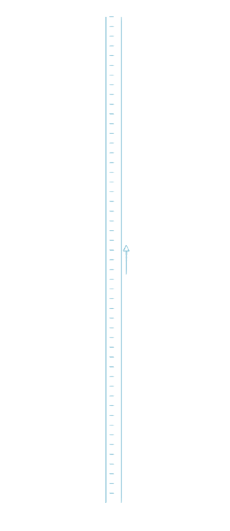
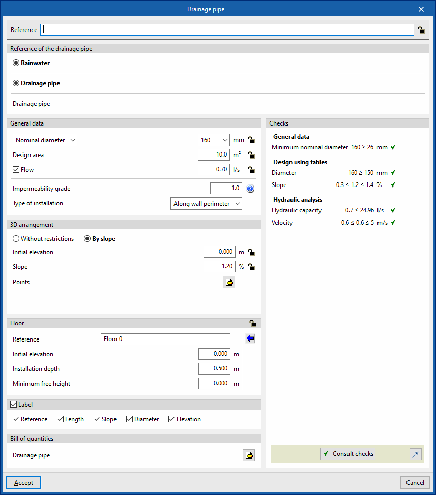
Inserts a drainage pipe in the water evacuation system.
When entering or editing a drainage pipe, the following parameters can be configured. Some parameters only appear if the "Simplified entry" option, which can be found in the "Design options" of the "General options", is kept deactivated:
- Reference
Element reference. This value can be locked or unlocked. If unlocked, the program will create or modify the reference when updating results. - Drainage pipe reference
Selects the type of drainage pipe by its reference. These types can be created and edited in “Drainage pipes” in the "Design and check options to be carried out" section in the "General options" of the "Project" group. - General data
Defines the element's general data. Some of these values can be locked or unlocked. If a value is locked, it is not modified when updating the results and remains unchanged.- Nominal diameter / External diameter / Internal diameter (Lock/Unlock)
Selects and defines the diameter of the drainage pipe. - Design area (Lock/Unlock)
Defines the design area associated with the drainage pipe. This option only appears if the "Discharge values defined in drainage units" checkbox is activated in the "Design options" of the "General options". If this value is unlocked, the program can modify it when updating results, taking the data from the projected area value of the drainage area where the drainage pipe is located. - Flow (optional) (Lock/Unlock)
Defines the flow rate of the drainage pipe and enables the "Hydraulic analysis" checks. - Impermeability grade
Used to define the impermeability grade in order to carry out the design of the element using tables. The program has an aid on the right which allows users to consult the minimum degree of impermeability required for walls and floors depending on the presence of water and the permeability coefficient of the ground. This option only appears if the "Minimum nominal diameter" checkbox is activated for the type of drainage pipe selected. - Type of installation (Underground / Along wall perimeter)
Selects whether the drainage pipe is laid under the floor or on the perimeter of a wall to be able to carry out the design of the element by means of tables. This option only appears if the "Minimum nominal diameter" checkbox is activated in the type of drainage pipe selected.
- Nominal diameter / External diameter / Internal diameter (Lock/Unlock)
- 3D layout
Defines the 3D layout of the element. This section only appears when editing a previously entered element. - Floor (Lock/Unlock)
Defines the floor data assigned to the element. This section only appears when editing a previously entered element. If this section is unlocked, the program can modify this data, which is generated according to the layout of the element in the model. Using the wizard available on the right, the data of a floor plan defined in the "Floor plans" section of the "Project" group can be imported.- Reference
- Initial elevation
- Installation depth
- Minimum free height
- Label (optional)
Manages the information visible in the element's label.- Reference (optional)
- Length (optional)
- Slope (optional)
- Diameter (optional)
- Elevation (optional)
- Bill of quantities
Controls the generation of the element's bill of quantities using filters.- Drainage pipe
- Consult checks
Consults and lists the checks carried out on the element, if defined in the selected drainage area type. - Design
This feature, accessed by clicking on the button in the bottom right-hand corner, is used to automatically design the parameters considered in the drainage area editing panel so that they comply with the defined checks.
Gutter
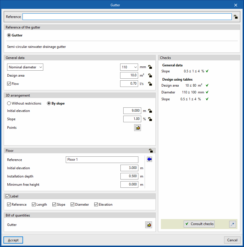
Inserts a gutter into the water evacuation system.
When entering or editing a gutter, the following parameters can be configured. Some parameters only appear if the "Simplified entry" option, which can be found in the "Design options" of the "General options", is deactivated:
- Reference
Element reference. This value can be locked or unlocked. If unlocked, the program will create or modify the reference when updating results. - Gutter reference
Selects the type of gutter by its reference. These types can be created and edited in “Gutters” in the "Design and check options to be carried out" section in the "General options" of the "Project" group. - General data
Defines the element's general data. Some of these values can be locked or unlocked. If a value is locked, it is not modified when updating the results and remains unchanged.- Nominal diameter / External diameter / Internal diameter (Lock/Unlock)
Selects and defines the diameter of the gutter. - Drainage units (Lock/Unlock)
Defines the number of drainage units associated with the gutter. This option only appears if the "Discharge values defined in drainage units" checkbox is activated in the "Design options" of the "General options" is activated and if "Drainage units" is selected in the "Dimensioning by tables" table, under "Analysis methods to use", in the selected gutter type. If this value is unlocked, the program can modify it when updating results, taking the data from the projected area value of the drainage area where the gutter is located. - Design area (Lock/Unlock)
Defines the design area associated with the gutter. This option only appears if the "Discharge values defined in drainage units" checkbox is activated in the "Design options" of the "General options" is activated and if "Drainage units" is selected in the "Dimensioning by tables" table, under "Analysis methods to use", in the selected gutter type. If this value is unlocked, the program can modify it when updating results, taking the data from the projected area value of the drainage area where the gutter is located. - Flow (optional) (Lock/Unlock)
Defines the flow rate of the gutter.
- Nominal diameter / External diameter / Internal diameter (Lock/Unlock)
- 3D layout (Lock/Unlock)
Defines the 3D layout of the element. This section only appears when editing a previously entered element.- Without restrictions
Directly enters the absolute X, Y and Z spatial coordinates of the points on the polygonal line defining the axis of the element. - By slope
Defines the 3D layout of the element by entering the on plan coordinates of the points through which it passes, the initial coordinate of the first point and the slope of the element. If the values for initial elevation and slope are unlocked, the program can adjust them when updating results.- Initial elevation (Lock/Unlock)
Defines the initial elevation of the element. - Slope (Lock/Unlock)
Defines the slope of the element. - Points
Defines the absolute X and Y plan coordinates of the points on the polygonal line defining the axis of the element.
- Initial elevation (Lock/Unlock)
- Without restrictions
- Floor (Lock/Unlock)
Defines the floor data assigned to the element. This section only appears when editing a previously entered element. If this section is unlocked, the program can modify this data, which is generated according to the layout of the element in the model. Using the wizard available on the right, the data of a floor plan defined in the "Floor plans" section of the "Project" group can be imported.- Reference
- Initial elevation
- Installation depth
- Minimum free height
- Label (optional)
Manages the information visible in the element's label.- Reference (optional)
- Length (optional)
- Slope (optional)
- Diameter (optional)
- Elevation (optional)
- Bill of quantities
Controls the generation of the element's bill of quantities using filters.- Gutter
- Consult checks
Consults and lists the checks carried out on the element, if defined in the selected drainage area type. - Design
This feature, accessed by clicking on the button in the bottom right-hand corner, is used to automatically design the parameters considered in the gutter editing panel so that they comply with the defined checks.

Longitudinal drain
Inserts a longitudinal drain in the water evacuation system.
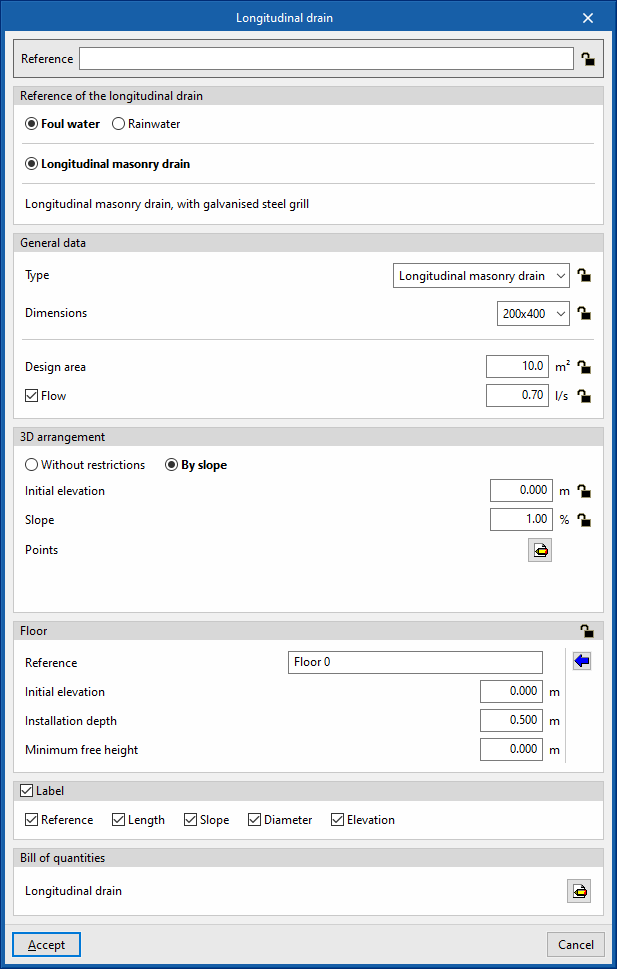
When entering or editing a longitudinal drain, the following parameters can be configured. Some parameters only appear if the "Simplified entry" option found in the "Design options" of the "General options" is kept deactivated:
- Reference
Element reference. This value can be locked or unlocked. If unlocked, the program will create or modify the reference when updating results. - Longitudinal drain reference
Selects the type of longitudinal drain by its reference. These types can be created and edited in “Gutters” in the "Design and check options to be carried out" section in the "General options" of the "Project" group. - General data
Defines the element's general data. Some of these values can be locked or unlocked. If a value is locked, it is not modified when updating the results and remains unchanged.- Type (Lock/Unlock)
Selects the type of material corresponding to the longitudinal drain. These materials can be created and edited in the "Longitudinal drains catalogue", in the "Material and equipment selection" section of the "General options" of the "Project" group. - Dimensions (Lock/Unlock)
Selects the dimensions of the longitudinal drain from those available in the type selected in the previous section. - Design area (Lock/Unlock)
Defines the design area associated with the longitudinal drain. This option only appears if the "Discharge values defined in drainage units" checkbox, found in the "Design options" of the "General options", is activated. If this value is unlocked, the program can modify it when updating results, taking the data from the design area value of the drainage area where the longitudinal drain is located. - Flow (optional) (Lock/Unlock)
Defines the flow rate of the longitudinal drain.
- Type (Lock/Unlock)
- 3D layout (Lock/Unlock)
Defines the 3D layout of the element. This section only appears when editing a previously entered element.- Without restrictions
Directly enters the absolute X, Y and Z spatial coordinates of the points on the polygonal line defining the axis of the element. - By slope
Defines the 3D layout of the element by entering the on plan coordinates of the points through which it passes, the initial coordinate of the first point and the slope of the element. If the values for initial elevation and slope are unlocked, the program can adjust them when updating results.- Initial elevation (Lock/Unlock)
Defines the initial elevation of the element. - Slope (Lock/Unlock)
Defines the slope of the element. - Points
Defines the absolute X and Y plan coordinates of the points on the polygonal line defining the axis of the element..
- Initial elevation (Lock/Unlock)
- Without restrictions
- Floor (Lock/Unlock)
Defines the floor data assigned to the element. This section only appears when editing a previously entered element. If this section is unlocked, the program can modify this data, which is generated according to the layout of the element in the model. Using the wizard available on the right, the data of a floor plan defined in the "Floor plans" section of the "Project" group can be imported.- Reference
- Initial elevation
- Installation depth
- Minimum free height
- Label (optional)
Manages the information visible in the element's label.- Reference (optional)
- Length (optional)
- Slope (optional)
- Diameter (optional)
- Elevation (optional)
- Bill of quantities
Controls the generation of the element's bill of quantities using filters.- Longitudinal drain
These options are the same as those available in the section "Design and check options to be carried out", which is accessed from the "General options" of the "Project" group.