Automatic generation of the layout of the water supply system
The program includes several features that automatically lay out the pipes of different parts of the water supply system in the "Water Systems" tab. The geometry proposed after the automatic layout generation process can be subsequently adjusted and modified to adapt it to the needs of the project.
Options in the "Generation" group
The options for the automatic generation of the pipe layout can be found in the new "Generation" group in the "Installation" tab:

The tools available are shown in increasing order of complexity and are as follows:
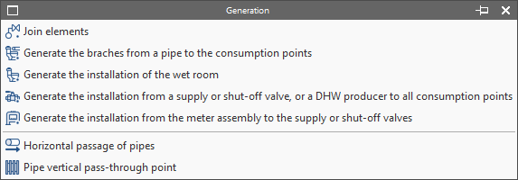
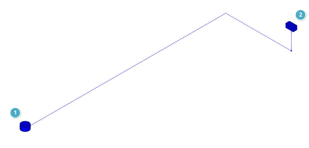
Join elements
Generates a pipe between two selected elements in the model.
- Examples:
- Generation of the pipe between the "Supply connection point" (1) and the "Meter pre-installation" or general building tap (2).
- Generation of the pipe between the "Meter pre-installation" and the "Shut-off valve" (in single valve installations) or the "Battery of meters" (in multi-subscriber installations).
Generate the branches from a pipe to the consumption points
Generates the individual branches from a controlled pipe route (which must be previously entered in the desired position) to the selected consumptions.
- Use sequence:
- Manual layout of the consumptions (1).
- Manual entry of the main supply pipe (2) following the geometry desired by the user.
- Selection of the manually entered pipe and the consumptions. As a result, the branches are automatically generated.
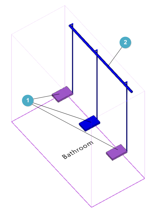
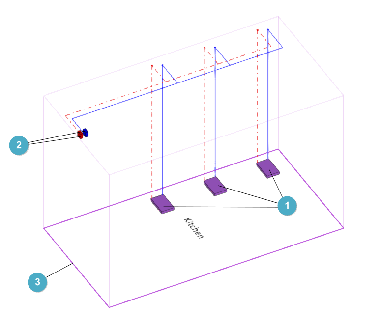
Generate the installation of the wet room
Generates the water supply system in the selected space, including the individual pipes and branches up to all the consumptions. When using this option, the "Properties - Space" panel that appears allows users to "Modify the configuration" of the space in which the system will be generated. If it is not modified, the configuration assigned to the type of the space from "General options" will be used.
- Use sequence:
- Manual layout of wet room consumption (1).
- Manual layout of wet room valves (2).
- Selection of the space (3). As a result, the installation is automatically generated.
| Note: |
|---|
| Taps and consumptions must be located inside the volume of the wet room space. |
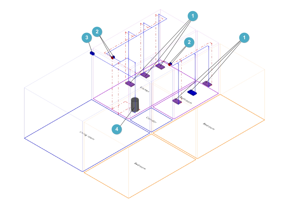
Generate the installation from a supply or shut-off valve, or a DHW producer to all consumption points
Generates the pipes from the shut-off valve or selected DHW producer to the previously entered consumptions.
- Use sequence:
- Manual layout of the consumptions (1).
- Manual layout of wet room valves (2).
- Manual layout of the shut-off valve (3).
- Manual layout of the DHW producer equipment (4).
- Selection of the shut-off valve / DHW producer. As a result, the pipe network is automatically generated from the wet room valves to the consumers. Each shut-off valve can be selected first to generate the cold water system and then the DHW generator can be selected to generate the domestic hot water system.
The program allows users to preview the result of the generation by passing the pointer over each of the elements mentioned above. By clicking on them, the generation is performed.
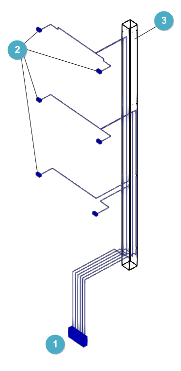
Generate the installation from the meter assembly to the supply or shut-off valves
Generates the pipes from the selected meter assembly to the previously entered shut-off valves.
- Use sequence:
- Manual layout of the "Meter assembly" (1).
- Manual layout of shut-off valves (2).
- Layout of a "vertical passage" of pipes (3).
- Selection of the meter assembly and the vertical passage. As a result, the pipes to the valves are automatically generated.
| Note: |
|---|
| The geometry of the "Vertical passage" of pipes must overlap with the space where the "Meter assembly" is positioned. Several "Elements" must be defined in the configuration of the passage equal to the number of shut-off valves set in the model. |
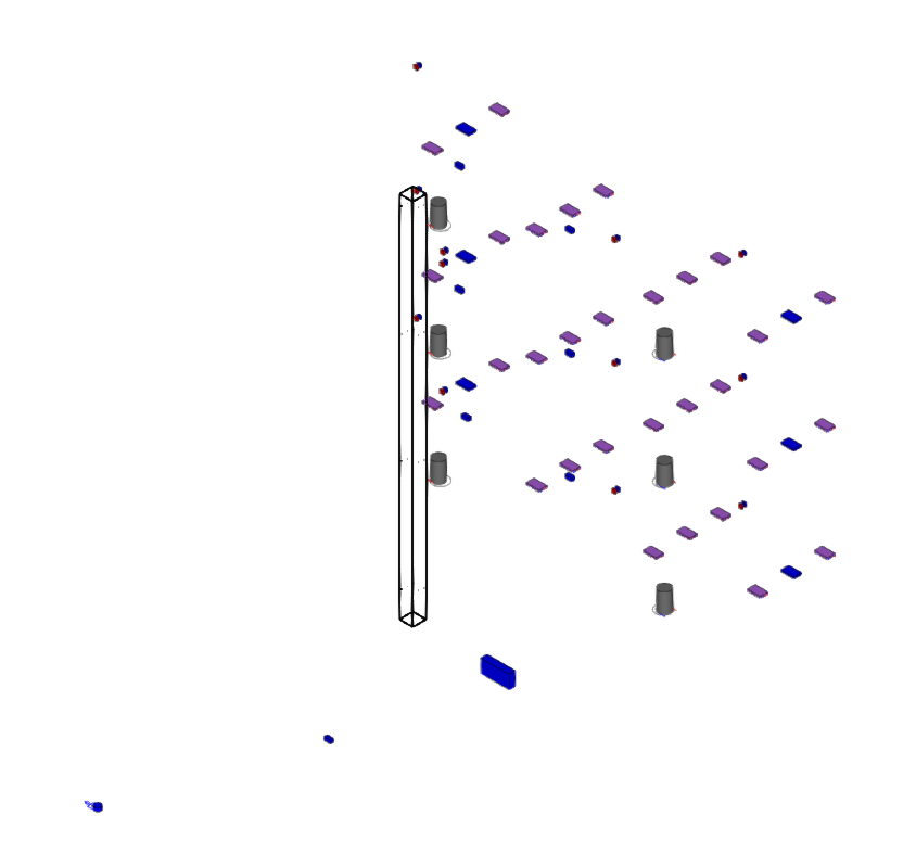
Before generation, the consumptions can be entered manually in their position or they can be generated by reading the BIM model, if it has information on the sanitary appliances. The rest of the elements necessary for the generation (main piping, shut-off valves, DHW production equipment, etc.) must be entered manually in the space before using the options mentioned above.
Initial starting point:
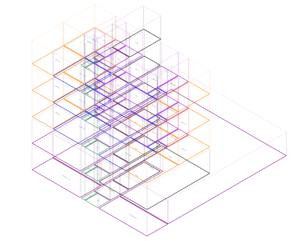
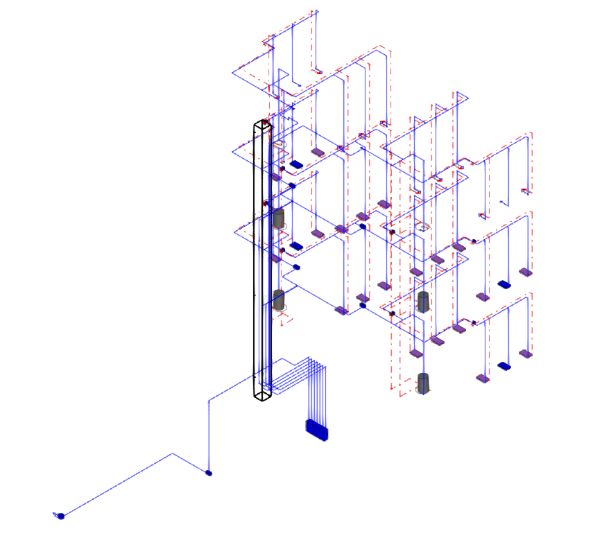
Result after generation processes:
Automatic layout control
Doors
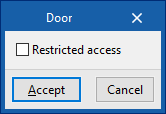
The program uses the doors read from the BIM model to generate the pipe layout.
The editing of the doors ("Edit" option in the "Edit" group) can activate the "Restricted passage" checkbox, which will prevent the generation of the path through the doors.
Pipe passages
Pipes can be forced to pass through certain regions of the model entered using the following options in the "Generation" menu:
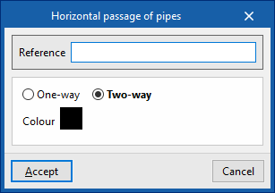
- Horizontal passage of pipes
The position of the horizontal passage of the pipes created in the generation process can be indicated or forced. This element can be placed between two spaces or between a shaft (vertical pipe passage) and a space. When entering a horizontal pipe passage, the following data must be entered:- Reference
Reference of the passage. - One-way / Two-way
Indicates if the pipe passage can be considered in one direction or in both directions. - Colour
Representation colour.
- Reference
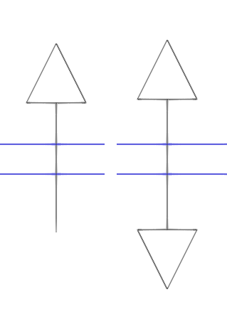
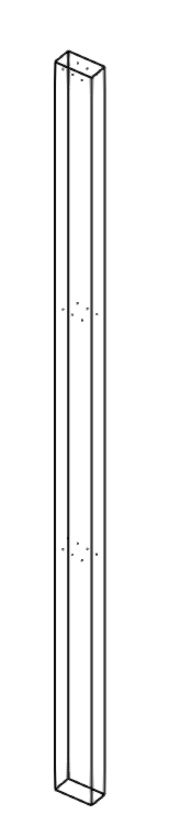
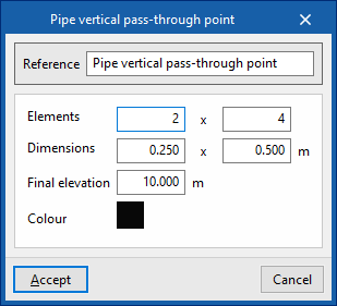
- Pipe vertical pass-through point
The position of the vertical pass-through point of the pipes created in the generation process can be indicated or forced. The insertion of a vertical pipe pitch can be complemented by the insertion of several horizontal pipe passages at the outgoing and incoming pipe entry points of the shaft on each floor. When inserting a vertical pipe pass-through point, the following data must be entered:- Reference
Passage reference. - Elements (m x n)
Number of available riser positions in the vertical pass-through point. - Dimensions (a x b)
On plan dimensions of the vertical pipe pass-through point. - Final elevation
Final elevation of the vertical pipe pass-through point in absolute coordinates. - Colour
Representation colour.
- Reference
These options simulate shafts or facility system passages in the model. If there are horizontal or vertical passages, the program will try to use their position to generate the pipe layout by passing through them instead of using the position of the doors.
| Note: |
|---|
| An example of use can be given in the design of a system that is laid through the floor of two rooms (for this purpose, the "Through floor" option must be checked in its type configuration). For pipes to pass from one room to the other directly, instead of looking for the position of the door, a "Horizontal pipe passage" can be entered in the area where the partition between the two rooms is located. |
Space configuration for automatic pipe layout purposes
The program can read the spaces from the BIM model and their configuration for the automatic generation of pipes in the process of creating a new job or through the corresponding options in the "Project" group.
First, the space types must be created in CYPEPLUMBING and then assigned to the spaces read from the BIM model.
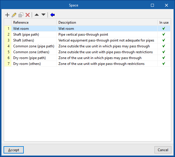
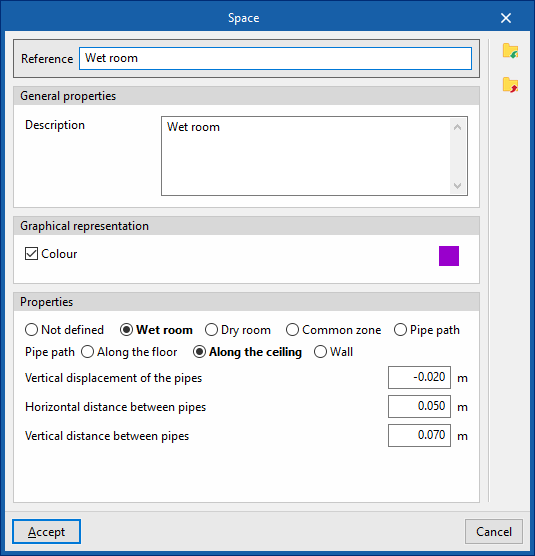
Creating space types
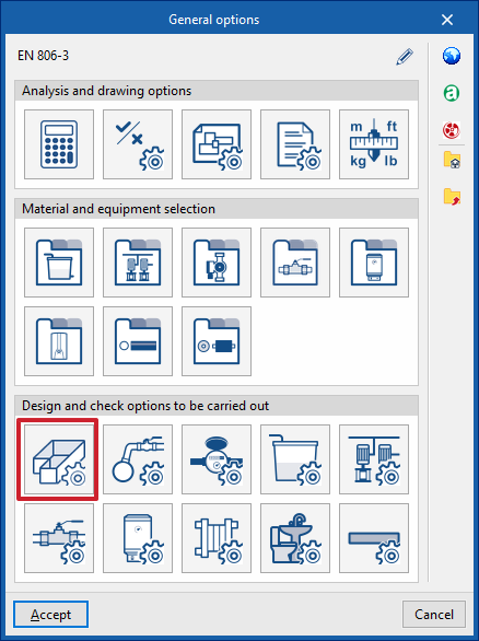
The creation of types of enclosures available in CYPEPLUMBING is carried out in the process of creating a new building or through the "General options" option and accessing "Spaces" This allows the program to indicate the reference, colour and properties of each type.
| Note: |
|---|
| As examples of space types to be defined, together with the options to be marked in their configuration, the following are listed: 1. Wet room (e.g. bathroom, kitchen, etc.): type "Wet room". 2. Shaft through which pipes can pass: "Pipe passage" type. 3. Shaft or opening through which pipes cannot pass (e.g. lift): "Common zone" type, "Restricted access" box activated. 4. Common zone where pipes can pass through (e.g. general circulation areas of the building): "Common zone" type. 5. Common area through which pipes cannot pass (e.g. stairs): "Common zone" type, "Restricted access" box activated. 6. Dry space that is part of a use unit in which pipes can pass through (e.g. corridor leading to the kitchen): "Dry room" type. 7. Dry room which is part of a unit of use through which no pipes can pass (e.g. bedroom): "‘Dry room" type, "Restricted passage" checkbox activated. |
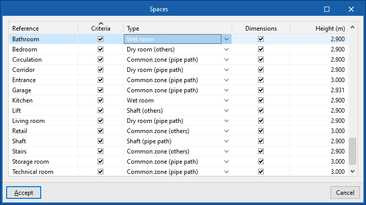
Assigning types to spaces read from the BIM model
Assigning the types of spaces created for the spaces read from the BIM model is done when the work is created or through the "Spaces" option in the "Project" group.
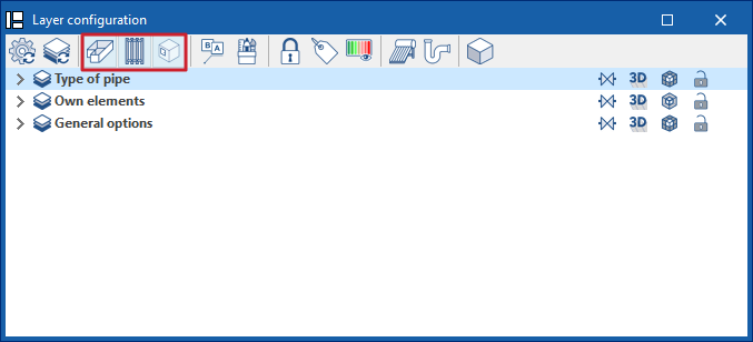
Related options in the "Layer configuration" panel
The toolbar of the "Layer configuration" panel offers specific options to control the display of spaces, shafts or pipe passages and doors or openings.