Tree of project elements in the thermal model
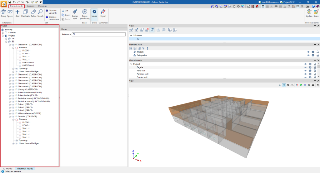
The project element tree describes the structure and organisation of all the elements that make up the thermal model of the building, which will be used in the thermal load analysis and incorporates their geometrical data.
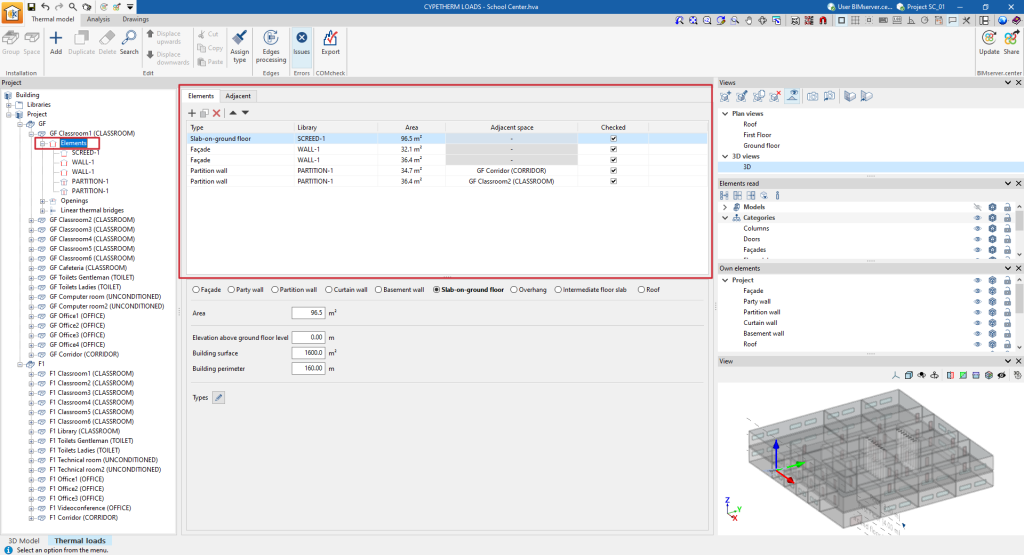
The management of elements of the building thermal model is carried out in the lower tab "Thermal loads", within the upper tab "Thermal model" and, in the "Project" definition area, in the "Project" tree located by default on the left-hand side.
The parameters of the elements arranged in this tree, including the spaces, building elements and linear thermal bridges, can be imported from the information of the different types of elements previously created in the libraries.
Generating the thermal model
The thermal model of the building can be generated in several ways:
- If the building has been drawn directly in the "3D model" tab, by clicking on the "Thermal model" option, the program switches to the "Thermal loads" tab and generates the thermal model of the building in this tab, including the tree of project elements.
- If the building has been drawn in other applications and the model information has been shared to a BIMserver.center project, the program can import it and generate the thermal model in the process of creating a new building or updating the project information.
Tools in "Installation": groups and spaces
The "Installation" group in the top toolbar can be used to manually enter groups and spaces. These elements are added to the project tree under the selected level. Thus, if the "Project" level is selected, the program creates a group or a space at the next level down.

These options are equivalent to the following, which appear in the context menu that appears when right-clicking on a level in the element tree: "Add (Groups)" and "Add (Spaces)".
Groups
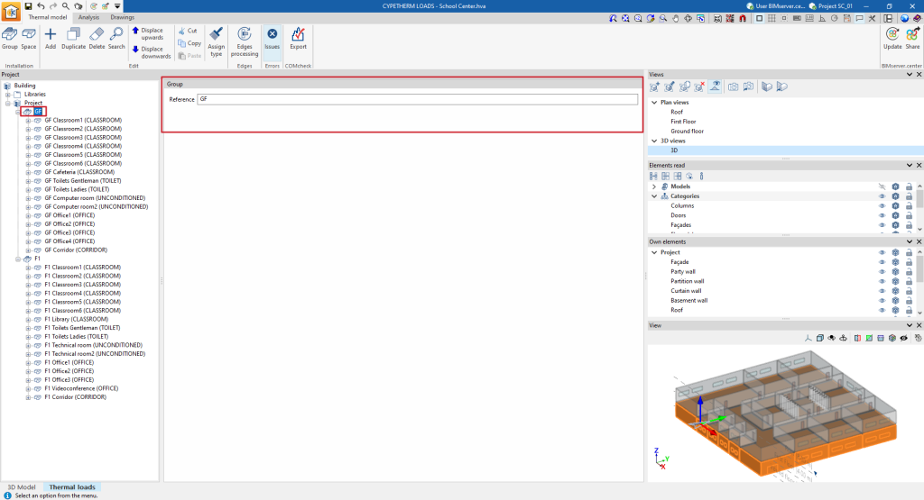
The "Group" option allows users to add a group in the project tree. Groups are groupings of spaces or other groups and the only data required is their reference:
- Reference
Group reference.
Spaces
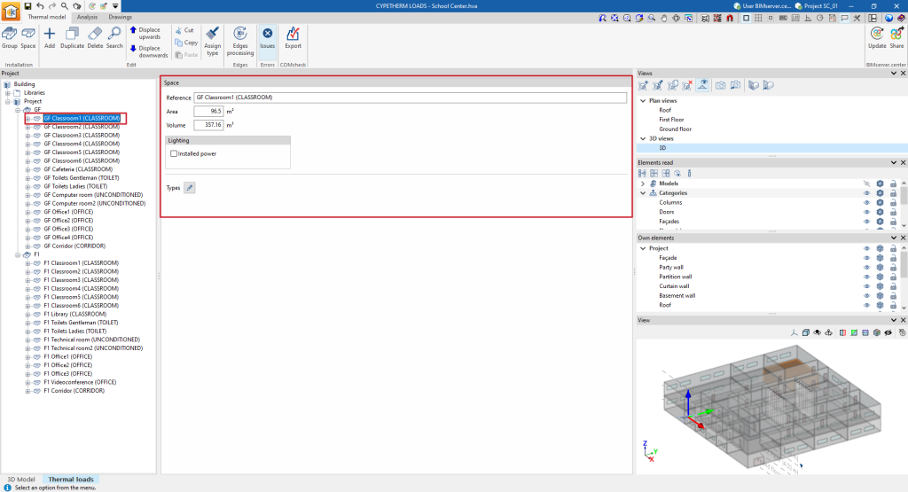
The "Spaces" option allows you to add a space in the project tree, either within a group or under the "Project" level. When adding a space, the program requires the following characteristics to be defined:
- Reference
Space reference. - Area
Floor area of the space. - Volume
Air volume of the space. - Lighting
The value of installed lighting power in each space can be taken from the BIM lighting design model included in the BIMserver.center project.- Installed power (optional)
The value of installed lighting power in each space can be taken from the BIM lighting design model included in the BIMserver.center project.
- Installed power (optional)
- Type
Directly edits of the parameters describing the space. A type already configured in the space libraries can be loaded using the button in the top right corner, which opens the "Import" window, where the desired type can be selected.
Elements
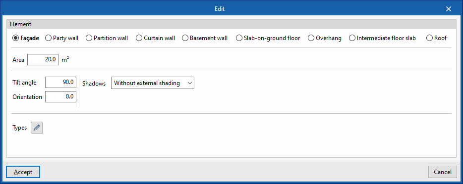
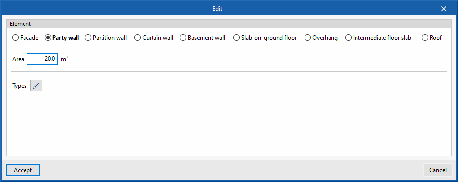
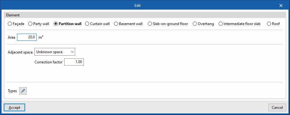
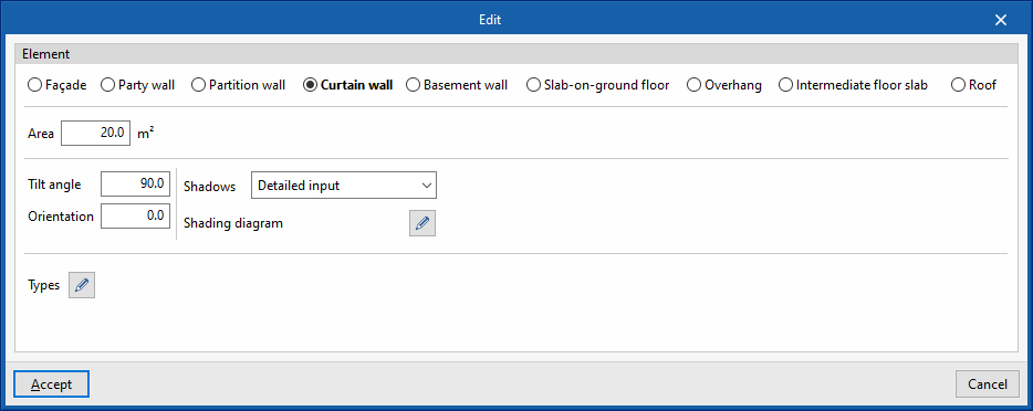
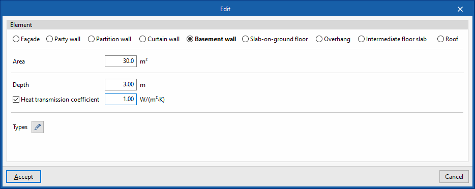
The elements are each of the façades, party walls, partition walls, curtain walls, basement walls, slab-on-ground floors, overhangs, floor slabs between floors and roofs that make up the geometry of a space.
To add elements, the "Add (Elements)" option in the context menu that appears when right-clicking on an ‘Elements’ level, located below the level of any space, can be used.
The data required by the program when entering each of the above-mentioned types of elements are as follows:
- Façade
- Area
- Tilt angle
- Orientation
- Shadows
- Without external shading
- Simplified input
- Constant shade percentage
- Detailed input
- Shading diagram
- Types
- Partition wall
- Area
- Adjacent space
- Unknown space
- Correction factor
- Adjacent space
- Select space
- Adiabatic element
- Unknown space
- Types
- Curtain wall
- Area
- Tilt angle
- Orientation
- Shadows
- Without external shading
- Simplified input
- Constant shade percentage
- Detailed input
- Shading diagram
- Types
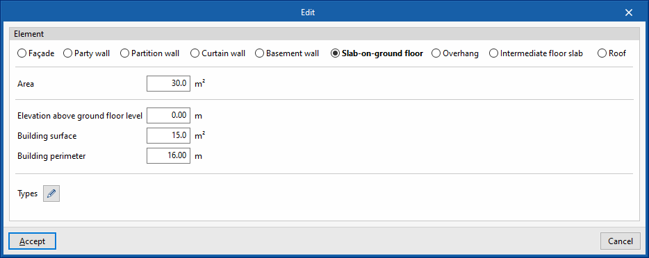
- Slab-on-ground floor
- Area
- Elevation above ground floor level
- Building surface
- Building perimeter
- Types
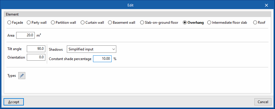
- Overhang
- Area
- Tilt angle
- Orientation
- Shadows
- Without external shading
- Simplified input
- Constant shade percentage
- Detailed input
- Shading diagram
- Types
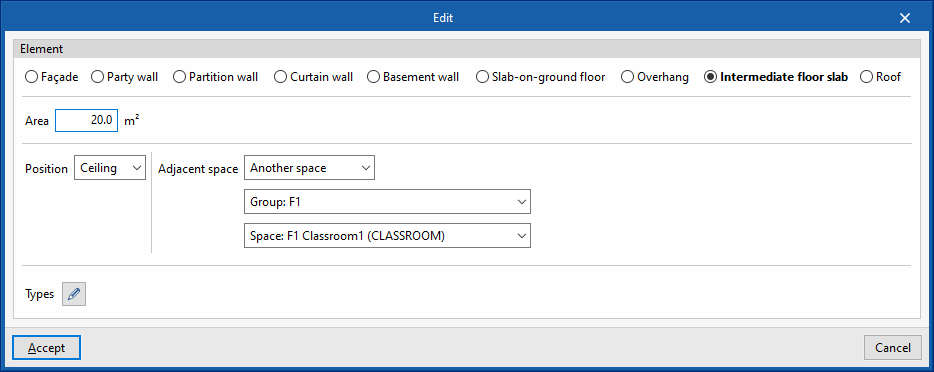
- Intermediate floor slab
- Area
- Position (Floor/Roof)
- Adjacent space
- Unknown space
- Correction factor
- Adjacent space
- Select space
- Adiabatic element
- Unknown space
- Types
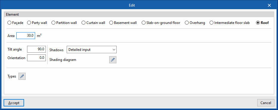
- Roof
- Area
- Tilt angle
- Orientation
- Shadows
- Without external shading
- Simplified input
- Constant shade percentage
- Detailed input
- Shading diagram
- Types
The elements in each space are listed in a table with the following information:
- Type
Type of element. - Library
Reference of the assigned library type. - Area
Element area. - Adjacent space
Reference of the adjacent space (in partition walls and slabs between floors). - Checked
By ticking the box in this column, the item is indicated as checked. - Warnings
Warnings on each element.
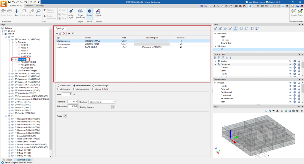
Openings
The openings that define the program in each space include doors, windows and skylights, both exterior and interior.
To add openings, you can use the "Add (Openings)" option in the context menu that appears when you right-click on an "Openings" level, located below the level of any space.
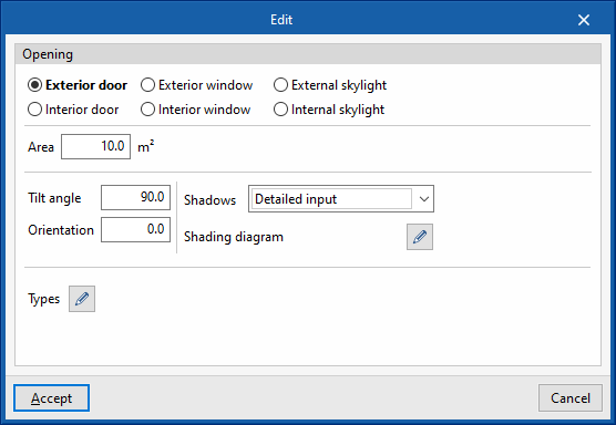
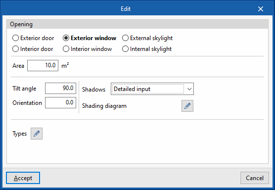
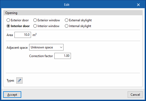
The data required by the program when entering each of the above-mentioned opening types are as follows:
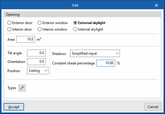
- Exterior door / Exterior window
- Area
- Tilt angle
- Orientation
- Shadows
- Without external shading
- Simplified input
- Constant shade percentage
- Detailed input
- Shading diagram
- Types
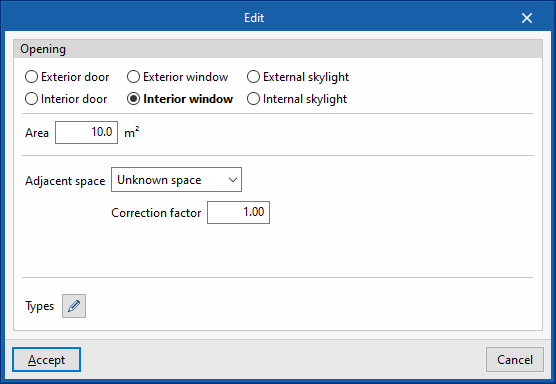
- Interior door / Interior window
- Area
- Adjacent space
- Unknown space
- Correction factor
- Adjacent space
- Select space
- Adiabatic element
- Unknown space
- Types
- External skylight
- Area
- Tilt angle
- Orientation
- Position /Floor / Roof)
- Shadows
- Without external shading
- Simplified input
- Constant shade percentage
- Detailed input
- Shading diagram
- Types
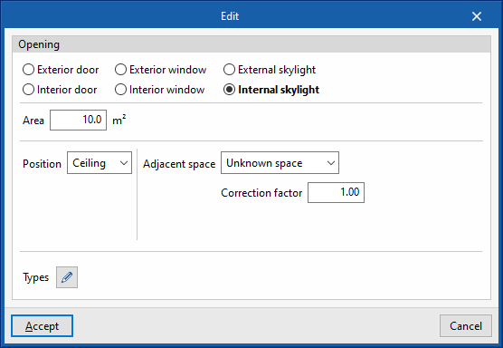
- Internal skylight
- Area
- Position (Floor / Roof)
- Adjacent space
- Unknown space
- Correction factor
- Adjacent space
- Select space
- Adiabatic element
- Unknown space
- Types
The openings in each space are listed in a table with the following information:
- Type
Type of openings. - Library
Reference of the assigned library type. - Area
Opening area. - Recinto colindante
Reference of the adjacent space (in interior openings). - By ticking the box in this column, it is indicated that the opening is checked.
- Warnings
Warnings on each opening.
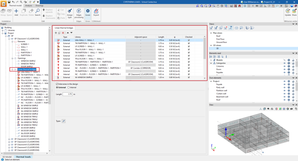
Linear thermal bridges
El programa permite definir los puentes térmicos lineales asociados a cada recinto.
To add openings, the "Add (Linear thermal bridges)" option can be used from the context menu that appears when right-clicking on a "Linear thermal bridges" level, located below the level of any space.
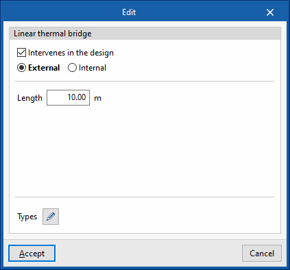
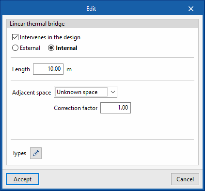
The data required by the program when entering the individual linear thermal bridges is as follows:
- Linear thermal bridges
- Intervenes in the design (optional)
- External / Internal
- Adjacent space
- Unknown space
- Correction factor
- Adjacent space
- Select space
- Adiabatic element
- Unknown space
- Length
- Types
The linear thermal bridges of each space are listed in a table with the following information:
- Type
Linear thermal bridge type (External / Internal). - Library
Reference of the assigned library type. - Adjacent space
Reference of the adjacent space (in interior linear thermal bridges). - Length
Linear thermal bridge length. - ψ
Linear thermal transmittance. - Checked
By ticking the box in this column, it is indicated that the linear thermal bridge is checked. - Warnings
Warnings on each linear thermal bridge.
Tools in the "Edit" group
The following tools in the "Edit" group in the top toolbar of the "Thermal model" tab are used to modify the element tree of the project:

- Add
Adds an item at the selected tree level. - Duplicate
Duplicates the selected item. - Delete
Deletes the selected item. - Search
Searches for an item by entering its reference text. - Displace upwards / Displace downwards
Changes the position of the selected item in the tree. - Cut / Copy / Paste
Cuts, copies and pastes elements on the desired lines. - Assign type
This tool is used to assign types from one element to others in the model view. To do this, click on the element the information is to be taken from. The program will highlight the elements assigned to the same type in orange, and the elements assigned to different types in yellow. When clicking on the latter, the type of the first element will be assigned to them.
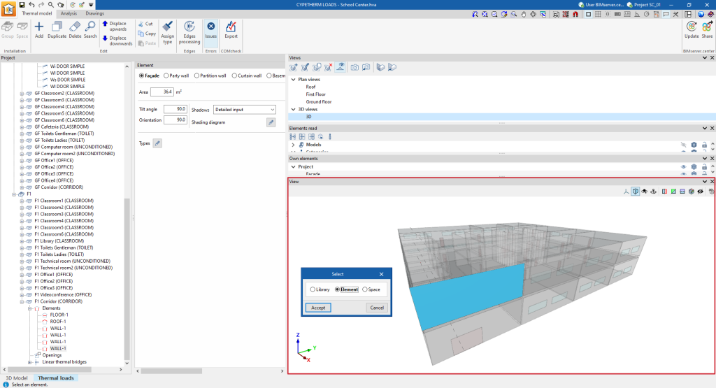
Selecting elements in the model view
The model view in the "‘Thermal model" tab at the bottom right shows and illuminates the selected tree elements. Furthermore, by clicking on the view itself, users can select the elements in the tree, the type they are assigned to in the library, or the space where they are located.

