
Hollow core slabs
With the "Hollow core slabs" module, CYPECAD analyses and designs hollow core floor slabs.
These are joist floor slabs discretised by bars every 40 cm. The geometrical characteristics and their resistance properties are defined in a slab characteristics sheet, which can be entered to create a library of lightweight slabs.
They can be analysed approximately according to the construction process by modifying the fixity at the edge according to a simplified method.
Entering hollow core slabs
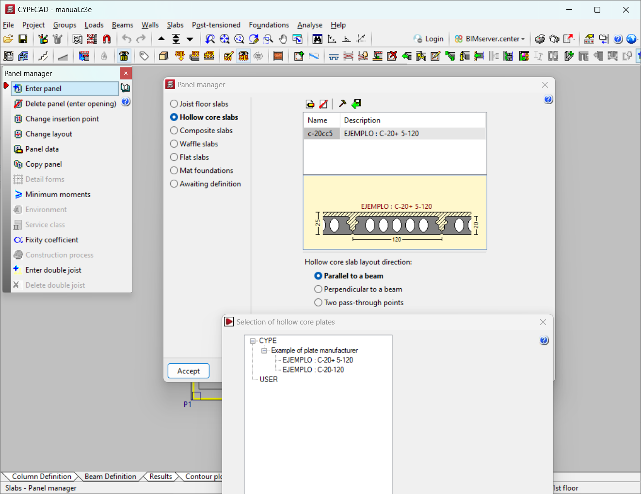
To select the "Hollow core slab" type, click on the "Layer" menu and then on "Panel manager". Here, the "Enter panel" option opens the "Panel management" window, in which the "Hollow core slabs" can be selected.
The following data must be defined when entering "Hollow core slab" type panels:
- Import from library
The type of slab must be selected from those available in the library or a new one must be defined. The library can also be edited from "Edit library", or the element selected from the list can be edited from "Edit".
- Hollow core slab layout direction
Three options are available: "Parallel to a beam", "Perpendicular to a beam" and "Two pass-through points".
Defining hollow core slabs
To define a hollow core slab, whether it is a hollow core plate, ribbed slab or any type of slab in any section, its geometrical data and mechanical characteristics must be defined.
The data contained in the data-sheet can be taken directly from the manufacturers, or the values can be entered for a specific panel that is to be prefabricated or built on-site. The data requested by the program includes the following:
- Reference
To identify the sheet using eight digits. - Descripción
The name of the plate. - Total depth of floor slab
The total depth of the plate plus the compression layer, if any. - Width of the plate
The width of the plate. - Compression layer thickness
The thickness of the compression layer, if any. - Minimum width of the plate
Is the smallest value that can be obtained by longitudinal trimming of a standard plate, as a result of the dimensions of the panel when it reaches an edge, normally a special plate being smaller in width than the standard plate. The width obtained from the latter special plate is between the standard value or width of the plate and this minimum width. - Self weight
This is the weight per square metre of the complete floor slab. - Concrete volume
This is the volume of the concrete in the filling of voids, joints between slabs and compression layer, if any. By default, it adopts the volume of the compression layer. - Minimum and maximum bearing
When the plate is deviated from the normal plate to the support, at each edge of the plate the delivery is different and can vary between minimum and maximum. If the maximum value is exceeded, the plate is chamfered. - Lateral bearing
This is the value that can overlap the plate laterally with a support parallel or slightly deviated from the longitudinal direction of the plate. - Plate concrete
This is informative data to show which materials were used to analyse the strength data of the section. - Layer and joint concrete
Same as above. - Top reinforcement steel
Same as above.
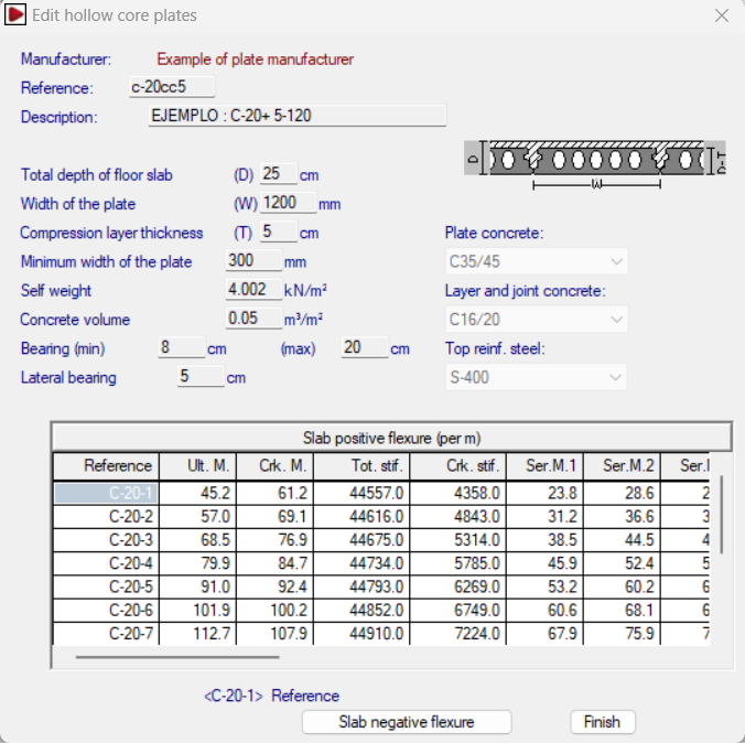
The strength data of the section is defined below:
- Slab positive flexure
This is the data of the slab with the joint filling concrete and the compression layer, if any.- Reference
- Ultimate moment
It is the maximum (ultimate) resisted moment. - Cracked moment
For the deflection calculation by Branson's equation. - Total stiffness
The total stiffness of the plate-concrete composite section is used to form the stiffness matrix of the bars in which the slab is discretised. - Cracked stiffness
For the deflection calculation by Branson's equation. - Service moment
Moment resisting class in prestressed concrete, which is not the same as the environment. The equivalence is as follows:- Environment I = Class III (Structures in building interiors or low humidity outdoor environments)
- Environment II = Class II (Structures in normal non-aggressive exteriors, or in contact with normal water or ordinary ground)
- Environment III = Class I (Structures in aggressive industrial or marine atmosphere, or in contact with aggressive soils or saline or slightly acidic water).
- Ultimate shear
Ultimate shear resisted by the total section. A distinction is made according to whether the design moment is greater or less than the decompression moment (Mg), resulting in two columns of data.
- Slab negative flexure
- Diameter / Diameter / Spacing
Two columns of diameters are specified, which allows a combination of two different diameters at a given spacing. With this amount distributed in the negative moment zone, the mechanical characteristics of the section are specified in each row. - Ultimate moment of section
The negative moment resisted by the section for a given reinforcement. - Cracked moment
For the deflection calculation by Branson's equation. - Total stiffness
For the deflection calculation by Branson's equation. - Cracked stiffness
For the deflection calculation by Branson's equation. - Ultimate shear
Shear resisted by the section for the given reinforcement.
- Diameter / Diameter / Spacing
En "Datos de paño" se puede seleccionar el ambiente, así como los coeficientes de empotramiento en bordes y los momentos mínimos para cada tipo de tramo, extremo, intermedio, aislado o vuelo.
Analysis process used
More information on the analysis process used can be found in the "Hollow core slabs" section in the CYPECAD calculations manual.
Results output
The following information is available:
- Moment and shear envelopes of the selected strip of the slab and averaged per metre width.
- Type of plate selected by analysis.
- The top reinforcement of negative reinforcement in supports, specifying the number, diameter, spacing and lengths of the bars, according to the views.
- Deflection information.
- Analysis errors, including moment, shear, deflection and environmental errors.
- The "Forces in hollow core slabs", "Hollow core plate quantities" and "Hollow core plate reinforcement quantities" reports.
The type of plate can be modified, as well as the negative reinforcement.
User license
For CYPECAD to be able to analyse and design hollow core slabs, the user license must include the "Hollow core slabs" module in addition to CYPECAD.
Other features
To be able to access other features offered by the program, there are several modules which can be found on the "CYPECAD modules" page.