Entering architectural elements
The following options can be found in the "Architecture" group in the main toolbar:

With these options, the building elements and structural elements of the building can be entered, depending on what is required for the subsequent analyses.
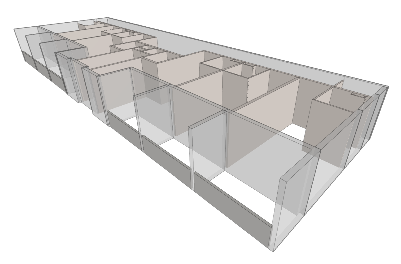
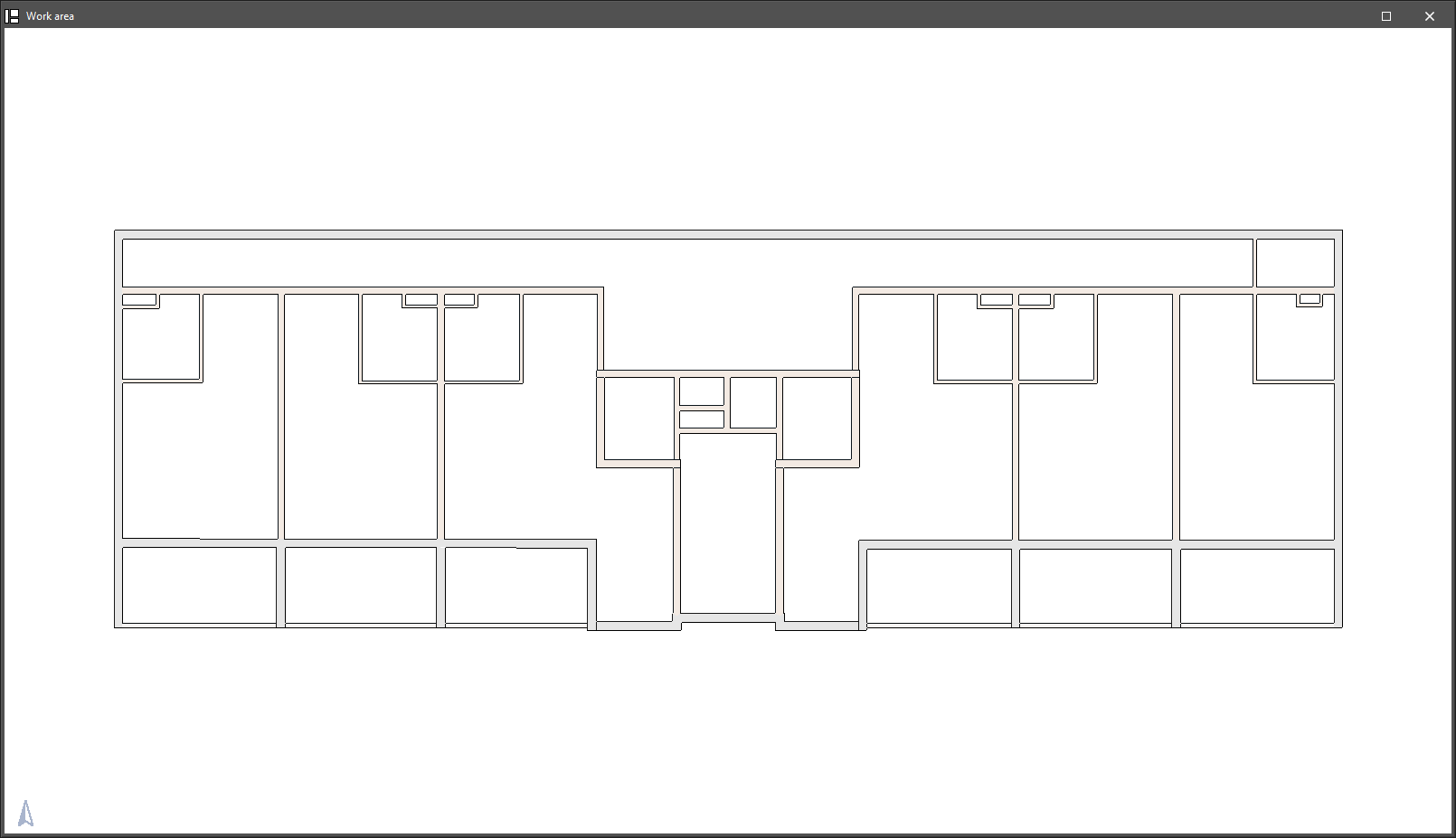
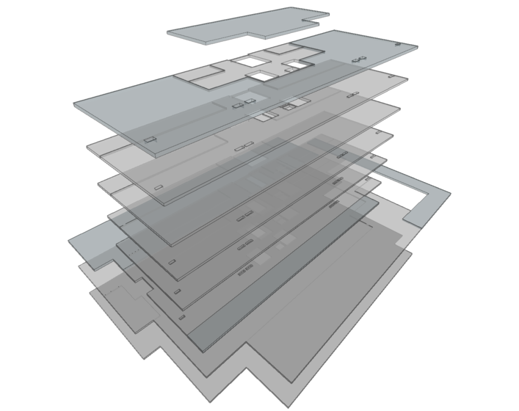
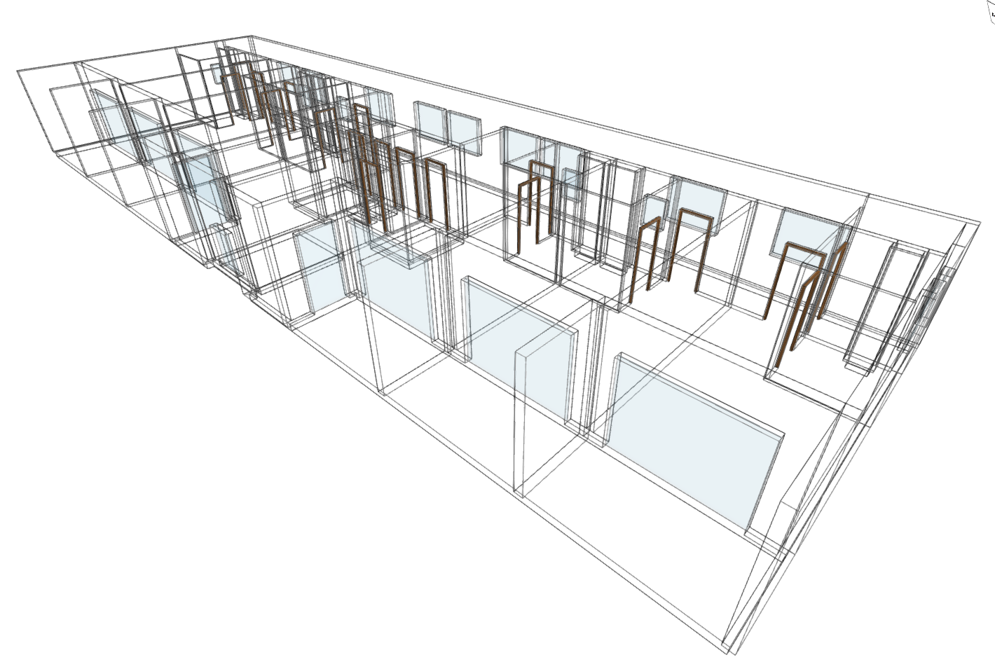
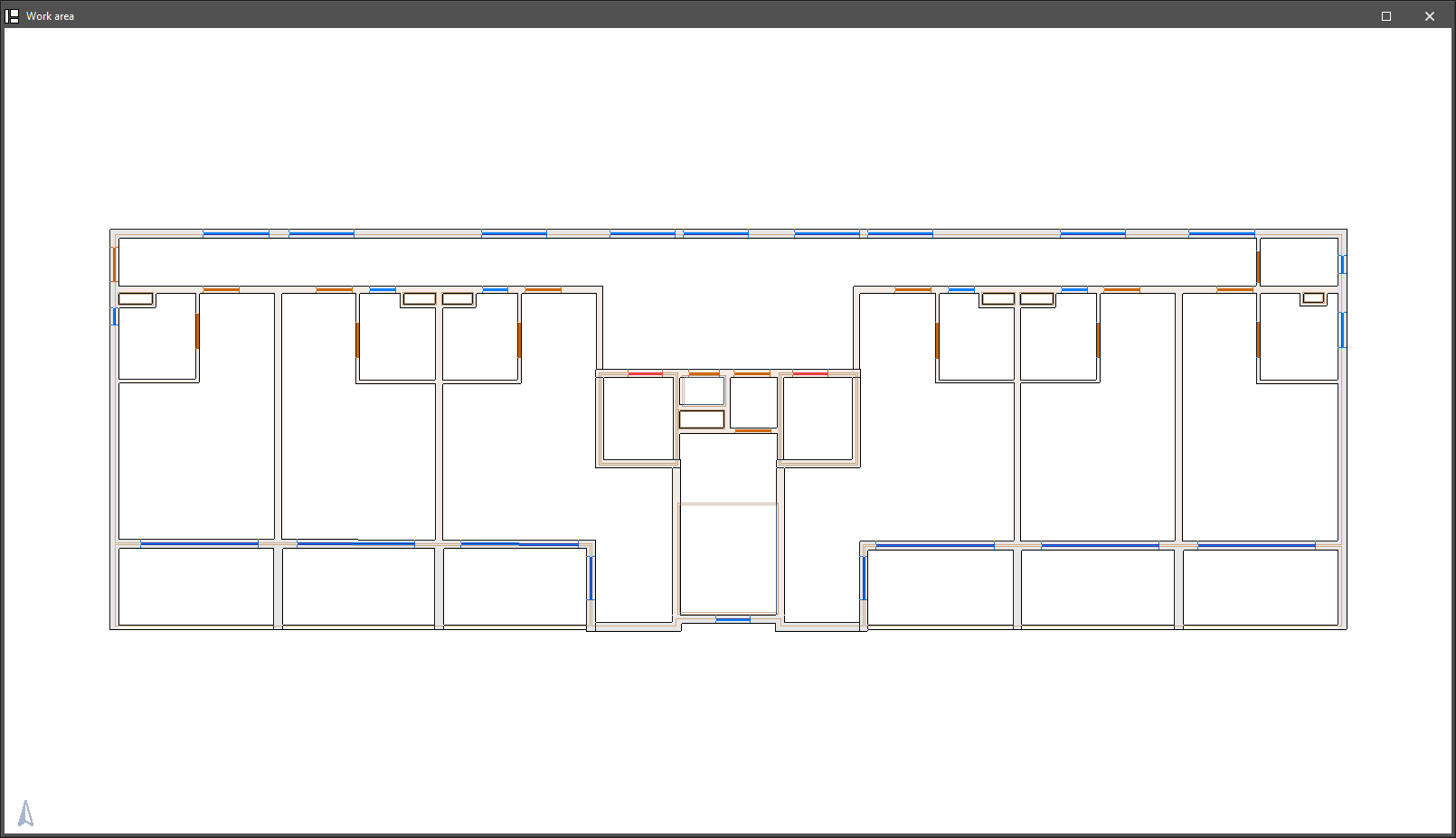
Modelling is carried out floor by floor in a 2D workspace, using 3D elements. The 3D view of the building can be displayed at any time, allowing the modelling process to be controlled.
Building modelling in IFC Builder can be done from scratch, with or without the help of templates or drawings in DXF, DWG, JPEG or BMP format. The use of these templates speeds up manual data entry.
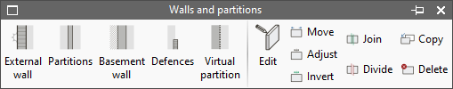
Walls and partitions
The "Walls and partitions" menu allows users to enter and edit elements of vertical geometry in the model, such as façades, party walls, partition walls, basement walls, defences and virtual partitions.
The types of walls and partitions available are the following:
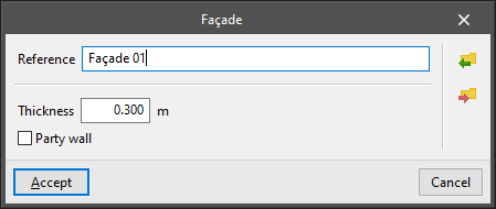
- Façade
Vertical separation element between a building space and the external environment or, if it is a party wall, between a building space and the space belonging to other buildings. The following parameters are defined for each type of façade:- Reference
- Thickness
- Party wall (optional)
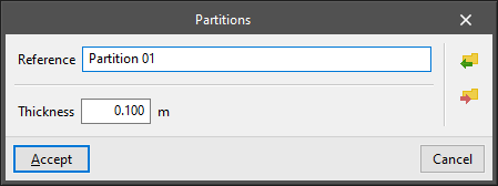
- Partitions
Vertical separation element between two interior spaces of the building. The following parameters are defined for each type of partition:- Reference
- Thickness
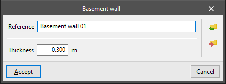
- Basement wall
Vertical separation element between a building space and the ground. The following parameters are defined for each type of basement wall:- Reference
- Thickness
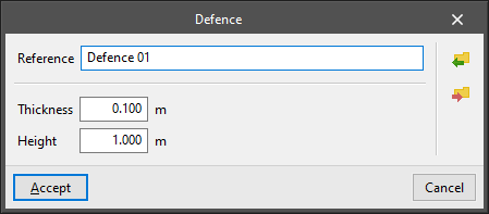
- Defences
This allows users to model railings, balustrades, perimeter parapets and other defences. The following parameters are defined for each type of defence:- Reference
- Thickness
- Height
- Virtual partition
A vertical element with no space delimitation thickness. It can be placed between two rooms in the model that are not separated by a physical barrier in the actual building (e.g. between an open kitchen and the living room).
The tools for editing walls and partitions are as follows:
- Edit
Allows users to edit the wall type to modify its characteristics or change the type assigned to the selected element. - Move
This allows walls and partitions to be repositioned by moving them either parallel to their position or by moving one of their ends. - Adjust
Allows users to adjust the position of the selected wall or partition with respect to the reference line, either by aligning them along one of their faces or along the central axis. - Invert
Reverses the direction in which the partitions are inserted. - Join
Joins two walls. - Divide
Divides a wall in two at a point determined by the user. - Copy
Copies the type from one wall to another. - Delete
Deletes the selected walls and partitions.
Floor slabs
The "Floor slabs" menu allows users to enter and edit elements of horizontal or inclined geometry in the model, such as screeds, intermediate floor slabs, flat roofs and sloped roofs.
The following types of floor slabs are available:
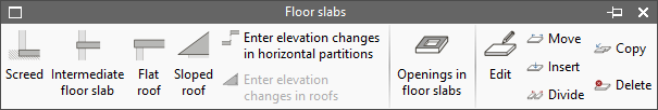
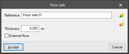
- Screed
Allows users to define screeds and suspended ground floors. The following parameters are defined for each type of slab:- Reference
- Thickness

- Intermediate floor slab
This allows users to enter an internal slab, which separates two rooms of the building, or a floor slab overhang, which separates a room at the top and the external environment at the bottom. The following parameters are defined for each type of intermediate floor slab:- Reference
- Thickness
- Overhang (optional)
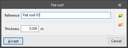
- Flat roof
Allows users to enter a flat roof. The following parameters are defined for each type of roof:- Reference
- Thickness
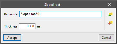
- Sloped roof
Allows you to enter the slope for a sloped roof. The following parameters are defined for each type of roof:- Reference
- Thickness
The program has two options for adjusting the geometry of horizontal floor slabs and sloped roofs:
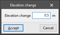
- Enter elevation changes in horizontal partitions
Allows a positive or negative elevation change to be applied to a floor slab, an intermediate floor slab or a roof with respect to the floor height. This elevation change shifts the floor slab parallel to the ground.
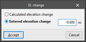
- Enter elevation changes in roofs
Allows a slope to be applied to the points of the polygonal surface that define a roof. This elevation change can be:- Calculated elevation change
The program calculates the elevation change of the point according to the elevation changes entered in the rest of the points of the polygonal surface that defines the roof's perimeter. - Entered elevation change
Users enter the elevation change of the selected point with respect to the height of the floor, either positive or negative.
- Calculated elevation change
From the "Floor slabs" menu, openings can also be entered in floor slabs by drawing their perimeter outline in plan on a previously entered floor slab:
- Openings in floor slabs
The tools for editing floor slabs are as follows:
- Edit
Allows users to edit the type of floor slab to modify its characteristics or change the type assigned to the selected element. - Move
Allows users to modify the shape of a slab by changing the position of the vertices or sides of the polygonal line that defines its perimeter. - Insert
Allows users to insert an additional point on the polygonal line that defines the perimeter of the slab. - Divide
Allows users to split a floor slab in two by drawing a polygonal line between two points on its perimeter. - Copy
Copies the type from one floor slab to another. - Delete
Removes the selected floor slabs.
Openings
The "Openings" menu allows users to enter and edit openings such as doors, windows, openings and skylights in the model. It requires the prior entry of the wall or floor slab where the opening will be made.
The types of openings available are as follows:
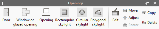
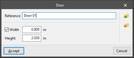
- Door
Enters a door in a wall or partition. The following parameters are defined for each door type:- Reference
- Width (optional)
If the width is deactivated, it will be defined when the door is entered graphically in the floor plan model. - Height
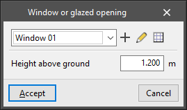
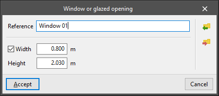
- Window or glazed opening
Enters a glazed opening in a wall or partition. The following parameters are defined:- Type parameters:
- Reference
- Width (optional)
If the width is deactivated, it is defined when the window or glazed opening is entered graphically in the floor plan model. - Height
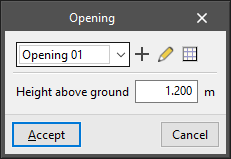
- Instance parameters:
- Height above ground
- Type parameters:
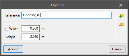
- Opening
Enters an uncovered opening in a wall or partition. The following parameters are defined:- Type parameters:
- Reference
- Width (optional)
If the width is deactivated, it will be defined when the opening is entered graphically in the floor plan model. - Height
- Instance parameters:
- Height above ground
- Type parameters:
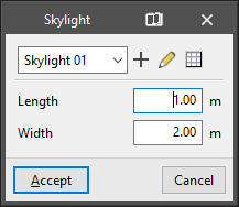
- Rectangular skylight
Allows users to enter a rectangular-shaped skylight in a floor slab. The following parameters are defined:- Type parameters:
- Reference
- Instance parameters:
- Length
- Width
- Type parameters:
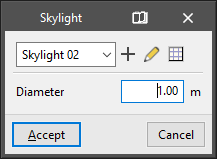
- Circular skylight
Enters a circular-shaped skylight in a floor slab. The following parameters are defined:- Type parameters:
- Reference
- Instance parameters:
- Diameter
- Type parameters:
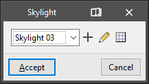
- Polygonal skylight
Enters a user-defined free-form polygonal skylight in a floor slab. The following parameter is defined for each type of polygonal skylight:- Reference
The tools for editing openings are as follows:
- Edit
Allows users to edit the type of opening to modify its characteristics or change the type assigned to the selected element. - Mover
Shifts an opening that has already been entered:
-For doors and windows or glazed openings, if the width of the opening is fixed, it changes its position to another place in the floor plan, keeping its dimensions constant. If the width is not fixed, it allows users to move one of the ends of the opening along the wall where it is located, increasing or decreasing its size.
-In circular and rectangular skylights, the position of the skylight can be shifted on plan.
-In polygonal skylights, the vertices and sides of the polygon defining the skylight can be moved. - Adjust
Shifts doors and windows to adjust their position to inside beams, outside beams or in the centre of the opening in the wall. - Rotate
Rotates a skylight around an axis perpendicular to the skylight that passes through its geometric centre. - Copy
Copies the type and characteristics from one opening to another. - Delete
Removes the selected openings.
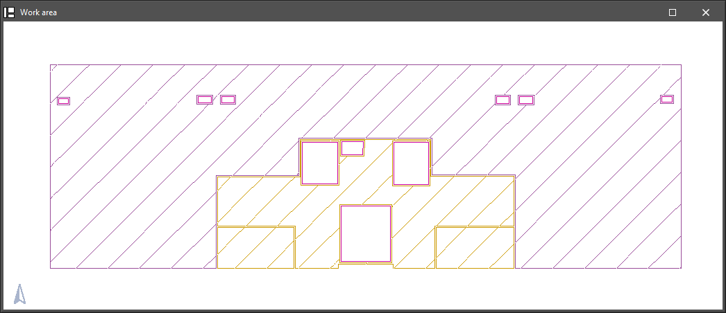
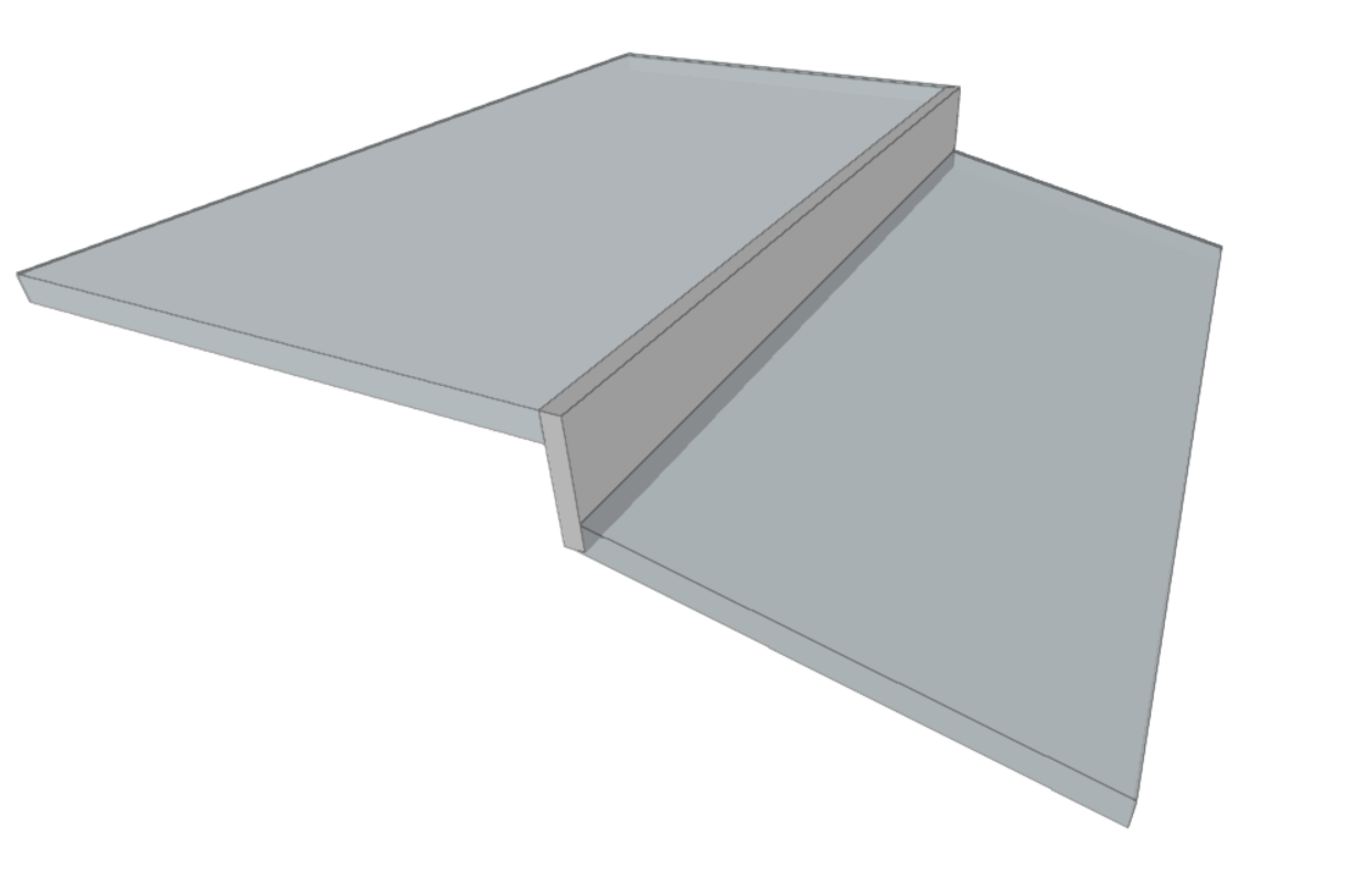
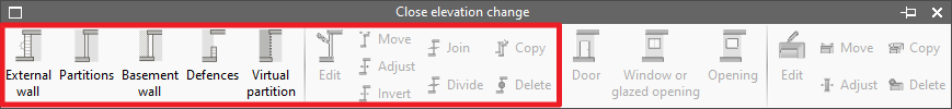
Closing the elevation change
Using this option, a closing can be entered in the slopes previously generated in the border between two floors of the same storey, after using the "Enter elevation changes in horizontal partitions" or "Enter elevation changes in roofs" options.
The closing of elevation changes can be categorised as any of the wall and partition types and has the same editing tools:
- External wall
- Partitions
- Basement wall
- Defences
- Virtual partition
- Edit
- Move
- Adjust
- Invert
- Join
- Divide
- Copy
- Delete
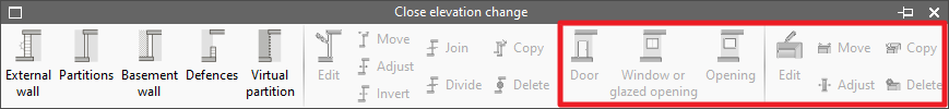
Also, in the menu accessible through this option, openings can be entered in the closings of slopes defined in the model. This menu offers editing tools for these levels:
- Door
- Window or glazed opening
- Opening
- Edit
- Move
- Adjust
- Copy
- Delete
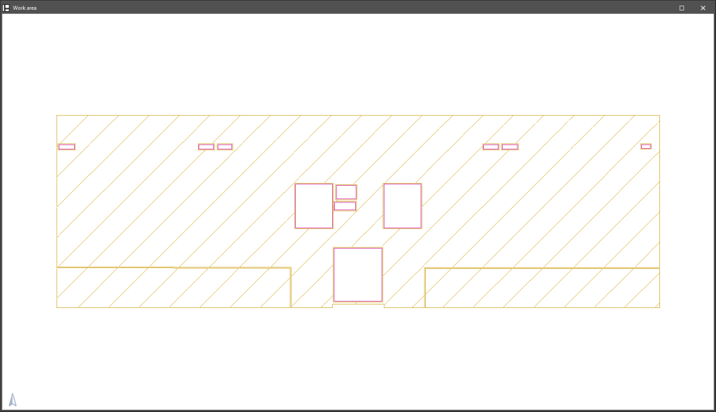
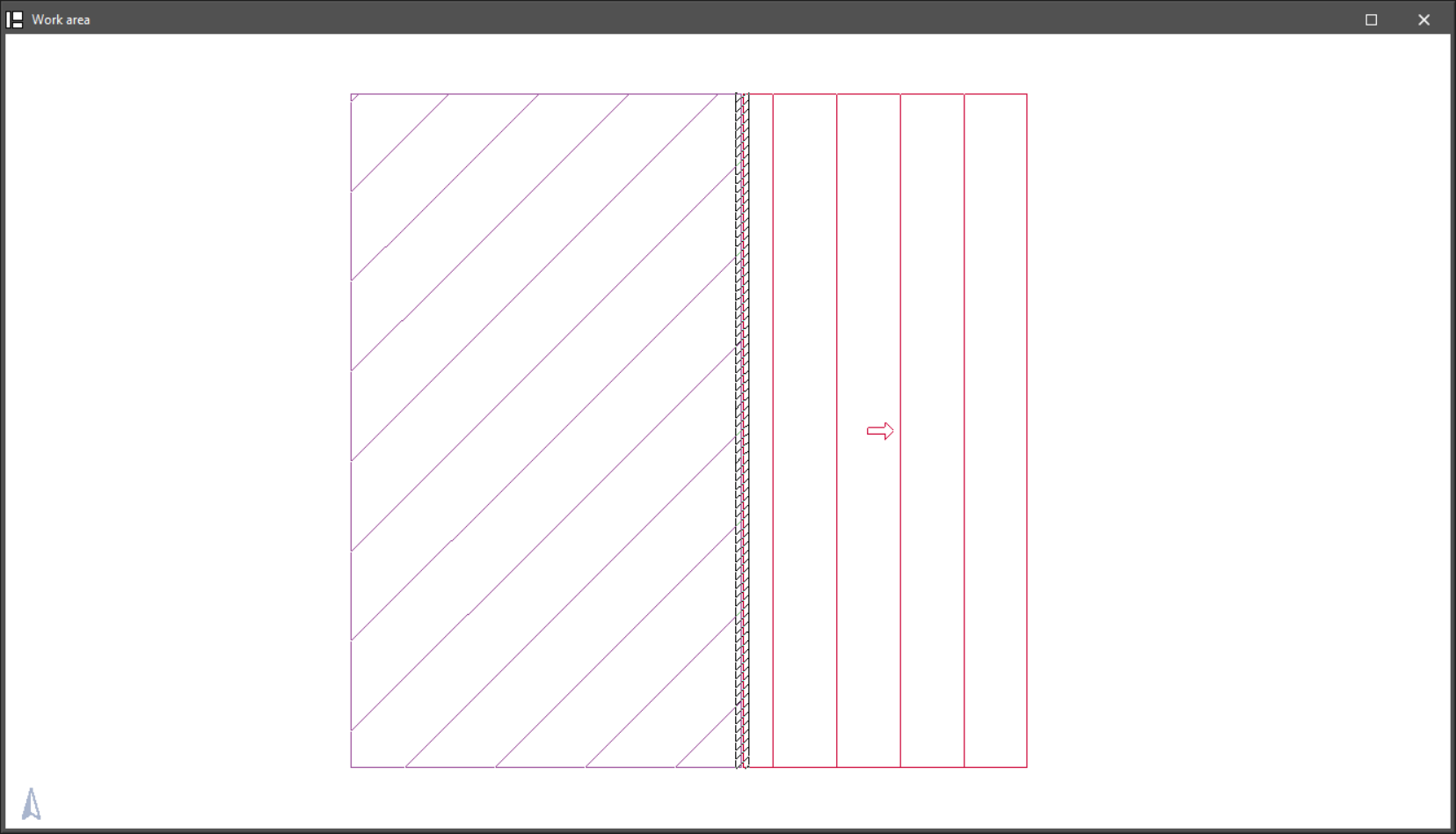
The closings of slopes are represented by a striped pattern on the ground plan.
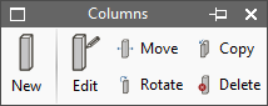
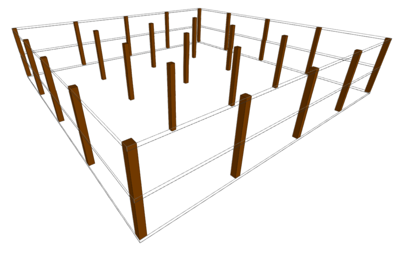
Columns
The "Columns" menu allows users to enter and edit rectangular or circular section columns in the model.
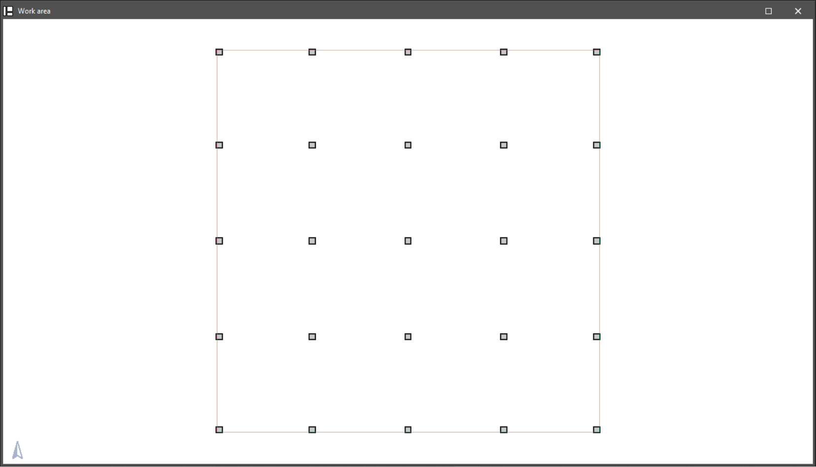
The option available for entering columns is as follows:
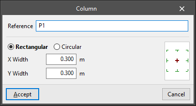
- New
Enters a column after defining the following parameters:- Reference
- Selection of type:
- Rectangular
- X width
- Y width
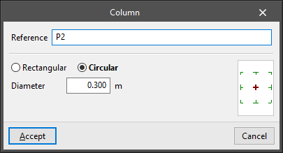
- Circular
- Diameter
- Rectangular
- Insertion point (centre, faces or corners)
The options available for editing columns are as follows:
- Edit
Allows users to edit the reference, type and characteristics of the selected column. - Move
Moves the selected column. - Rotate
Rotates the selected column on plan. - Copy
Copies the characteristics of one column to another. - Delete
Removes the selected columns.