
Options on the "Assembly" tab
The "Assembly" tab allows you to display a graphical representation of the enclosures, components and layout of the switchgear for the electrical panels previously defined in the file.
The options on this tab are as follows:
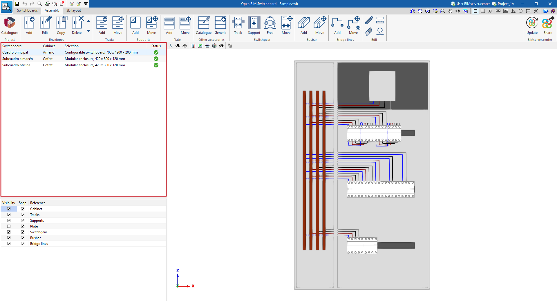
List of envelopes
The left-hand side of the interface displays a list of the enclosures defined using the options described below. The following information is shown for each box:
- Frame
Reference number of the frame associated with the box. - Box
Box reference. - Selection
Details of the selected box. - Status
Displays the status of the box. Clicking on it displays any associated issues, if there are any.
The box selected from the list will be displayed in the main workspace, in the centre of the interface.
Visibility and snapping options
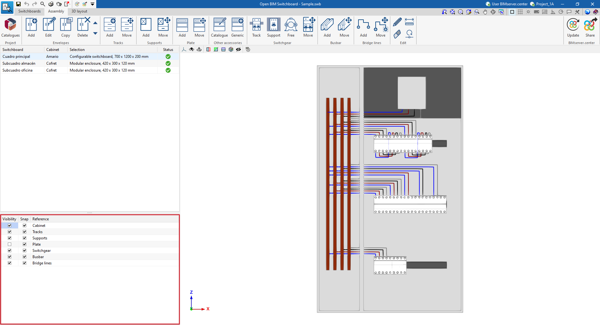
The panel at the bottom of the left-hand side allows you to control the "Visibility" of the elements added by category, as well as the option to "Snap" them when using the element insertion and drawing tools.
Importing catalogues
In the "Project" section of the main toolbar, you will find the option that allows you to download manufacturer catalogues via the connection to the Open BIM Database, making it easier to enter data into the program for project development:

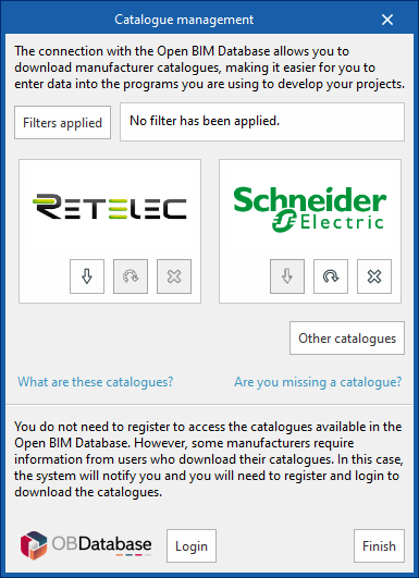
Clicking on this option opens a window showing the available manufacturer catalogues.
Download catalogues
The following options are displayed for each manufacturer:
- Download
Download the manufacturer’s catalogue. The products in the catalogue will be available in the project. - Update
Updates the catalogue for the selected manufacturer to the latest version, deleting the version previously downloaded to the project. - Delete
Deletes the selected manufacturer's catalogue. The products in the catalogue will no longer be available in the project.
Connection to the Open BIM Database
At the bottom of this dialogue box, the program allows you to log in using an Open BIM Database account and password.
The products from the downloaded catalogues can be selected when defining the other elements.
Creating and editing envelopes
The "Envelopes" section of the main toolbar contains the options for defining the envelopes or enclosures for the project's electrical panels:

- Add
- Edit
- Copy
- Delete
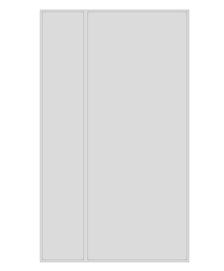
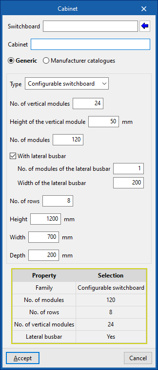
When adding enclosures, if frames have been entered in the "Switchboards" tab, the wizard allows you to import their reference using the wizard on the right-hand side to link them to the enclosure being added. When doing so, you can choose to "Show only those frames that do not include any boxes" (to add boxes to frames that do not yet have them) or "Show all panels, including those that do not include a case".
You can define a "Generic" item or use one of those available in the "Manufacturer catalogues". In the latter case, you can perform an "Automatic selection" from the downloaded catalogues using the relevant option.
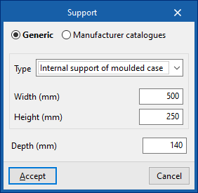
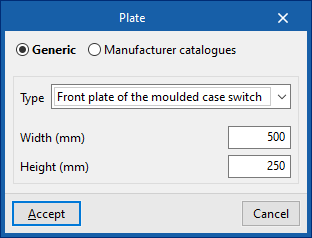
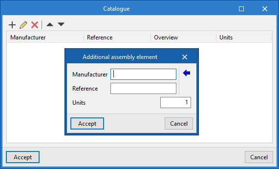
Inserting tracks, brackets, plates and other fittings
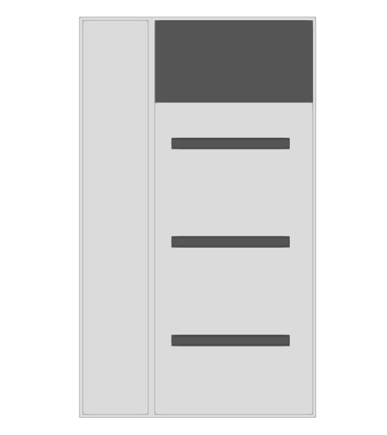
The following sections of the main toolbar contain the options for adding tracks, supports, plates and other fittings to each of the enclosures or boxes selected in the list above:

- "Tracks" section
- Add
- Move
- "Supports" section
- Add
- Move
- "Plates" section
- Add
- Move
- "Other fittings" section
- Catalogue
- Generic
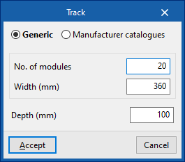
You can define a "Generic" element or use one of those available in the "Manufacturer catalogues".
Each of these elements can be placed on the panel in the main workspace, located in the centre of the interface.

Inserting switchgear
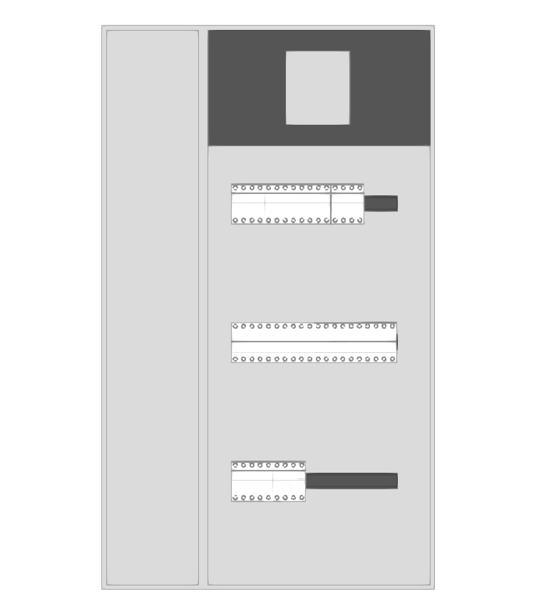
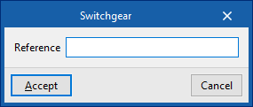
In the "Switchgear" section of the main toolbar, you will find the options that allow you to place the devices for each of the project’s switchboards in their correct positions:

- Track
Position a predefined track. - Support
Positions a predefined support. - Free
Positions a device freely within the panel. - Move
Moves a previously selected device.
Each device can be positioned in the main workspace, located at the centre of the interface, in the corresponding switchboard, track or support that has been previously defined.
Installing busbars and bridge lines
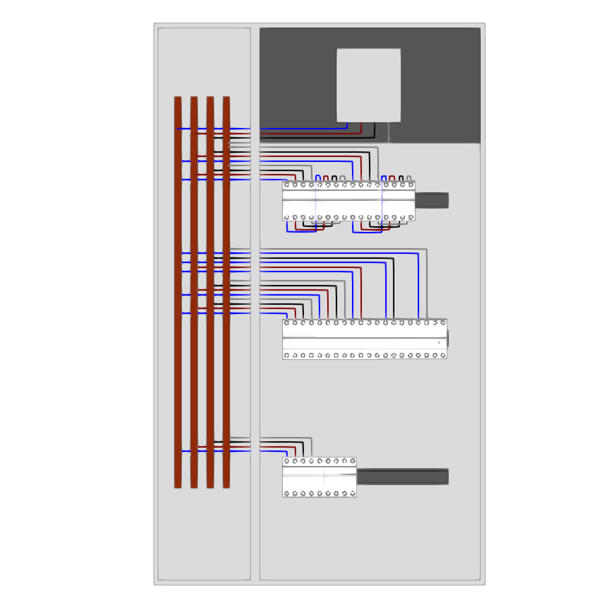
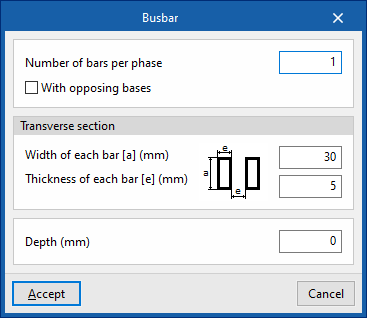
The following sections of the main toolbar contain the options for adding busbars or bridge lines between devices and busbars in each of the enclosures or boxes selected in the list above:

- "Busbars" section
- Add
- Move
- "Bridge Lines" section
- Add
- Move
Each of these elements can be placed in the main workspace, located in the centre of the interface.

Editing tools
The "Edit" panel provides the following tools for editing the elements displayed in the workspace:

- Edit
Edits the settings for the selected element. - Delete
Deletes the selected element. - Measure lengths
Measures the distance and area between the selected points. - Rotate
Rotates elements that can be rotated.
