Introduction
Open BIM Switchboard is a program that can be used to design the enclosures present in the electrical system, such as switchboards, distribution panels and control and protection boxes.
When starting to work with Open BIM Switchboard, users can link to a previously created BIM model. The program can then import the information of the electrical system analysed in other tools, such as the existing panels and sub-panels, together with their switchgear, including busbars and bridgelines. It also imports the visualisation of the building geometry, if it exists in that model.
In any case, Open BIM Switchboard can also be used to design envelopes from scratch, without the need for the BIM model to contain geometrical information about the building or the designed system or switchgear.
Workflows supported by the program
As Open BIM Switchboard is an Open BIM tool connected to the BIMserver.center platform, it offers a range of workflow options.
Data entry
Open design
- Free design of the switchboard by manually entering its components in Open BIM Switchboard.
Data import
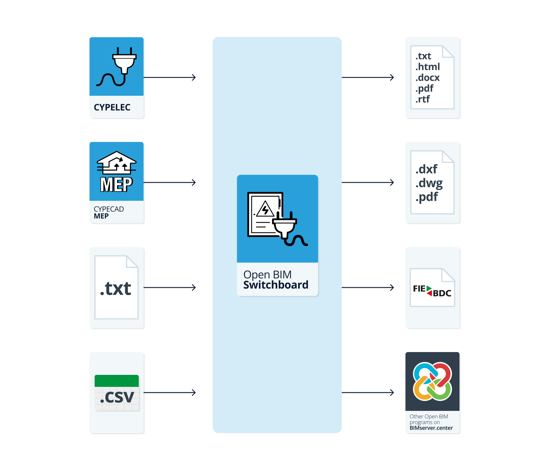
If the Open BIM Switchboard project is linked to a BIM project on the BIMserver.center platform, it is possible to import the electrical switchboards and sub-switchboards for the installation, along with the switchgear for each one, including the definition of busbars and jumper lines, based on the information extracted from the BIM model. Once the panels and sub-panels have been generated, they can be modified using the relevant tools without any restrictions. The available options include the following:
- Importing data on low-voltage electrical systems designed in CYPELEC.
- Importing data on low-voltage electrical systems designed in CYPECAD MEP.
- Importing data on low-voltage electrical systems designed using the following external software programs: BTwin, CIEBT and TeKton3D.
Alternatively, it is also possible to import data created in BTwin or CIEBT from .txt files, and in TeKton3D from .csv files, without needing to link to a BIMserver.center project.
Data output
- Exporting reports to HTML, DOCX, PDF, RTF and TXT formats.
- Exporting drawings to DXF, DWG and PDF formats.
- Exporting the bill of quantities to FIEBDC-3 format.
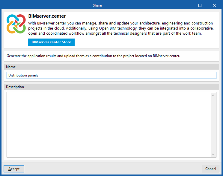
- Exporting information generated using Open BIM Switchboard to the BIMserver.center platform. This allows authorised project participants to view it.
Work environment
The Open BIM Switchboard interface is divided into three tabs with different work environments: "Switchboards", "Assembly" and "3D layout":
"Switchboards" tab
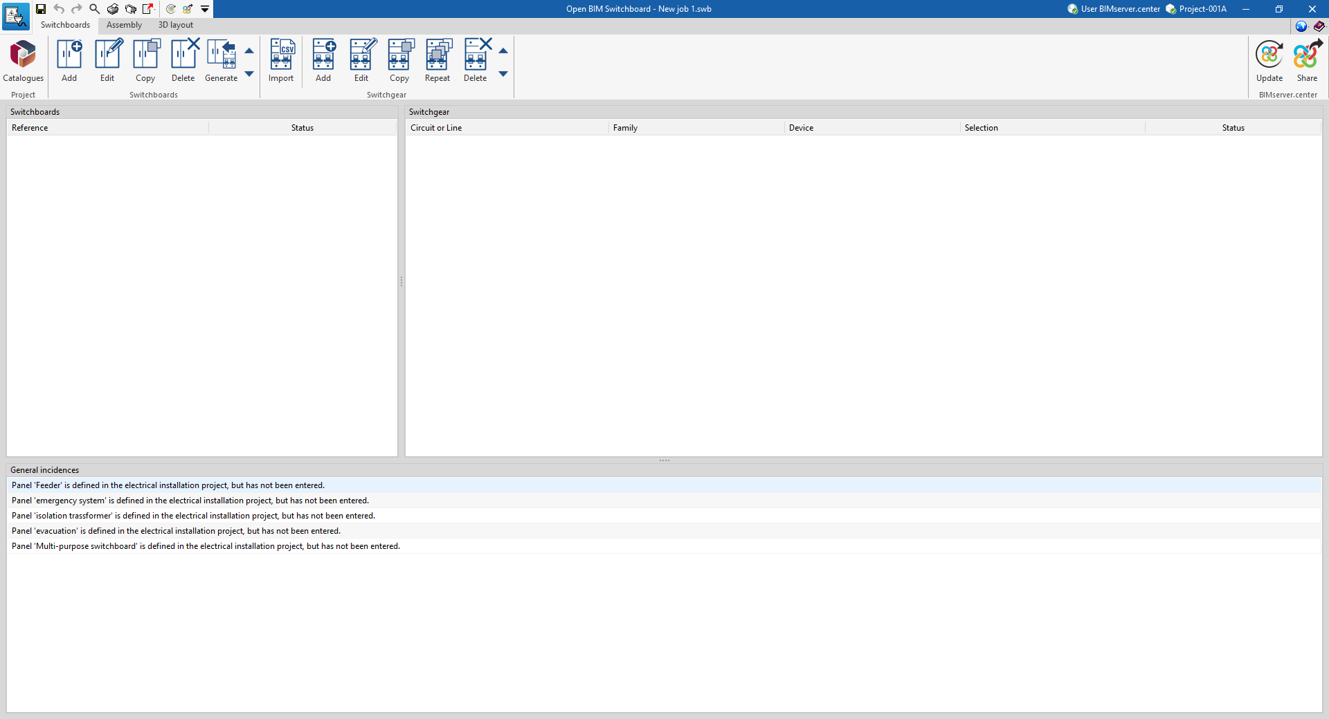
The "Switchboards" tab has a work environment that allows you to define the electrical switchboards of the system included in the file and their associated switchgear.
This tab displays the following:
- An upper toolbar containing the tools for: defining the catalogues and importing the electrical system project; entering, editing or generating the electrical panels; and importing, entering or editing the switchgear associated with each panel.
- On the left, a panel showing a report with each of the defined panels.
- On the right, a list of devices describing the switchgear associated with the switchboard selected on the left.
- At the bottom, a display of the general incidents detected by the program.

"Assembly" tab
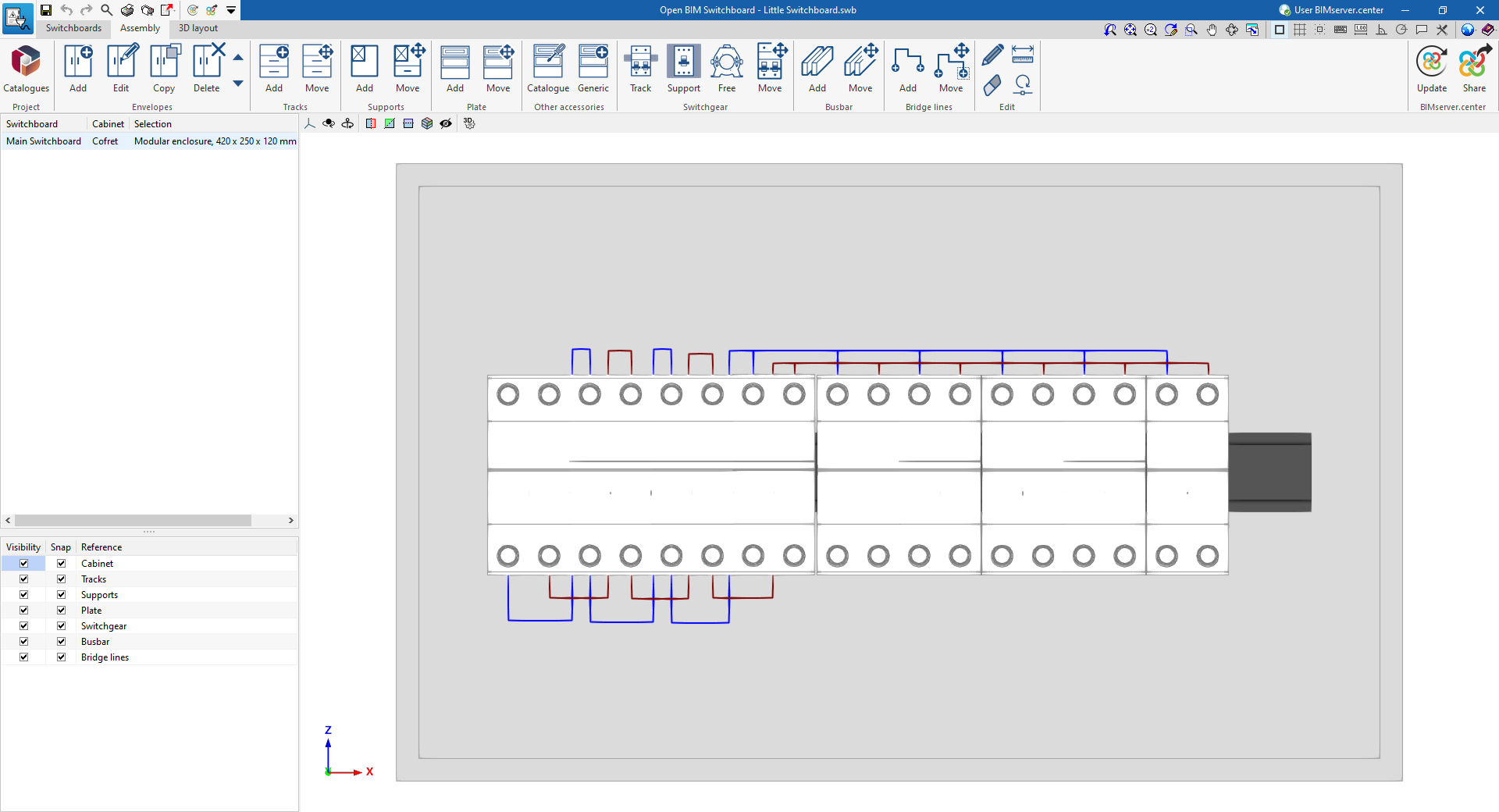
The "Assembly" tab has a work environment that allows you to detail the enclosure data of each of the switchboards (defined in the "Switchboards" tab) and to arrange elements such as rails, supports, plates, switchgear, busbars and bridge lines inside the switchboards.
This tab displays the following:
- An upper toolbar containing the tools for: defining project catalogues; entering or editing enclosures; defining tracks, supports, plates and other fittings; arranging the switchgear in the switchboard; adding or moving busbars; entering bridge lines. The editing tools are also located here.
- On the left-hand side, a panel showing a list of boxes, indicating the switchboard to which each one is associated, as well as a tool for managing the visibility and snapping of the elements arranged in the work area, sorted by category.
- On the right, the work area, where the box selected in the list on the left-hand side is displayed and detailed.
"3D layout" tab
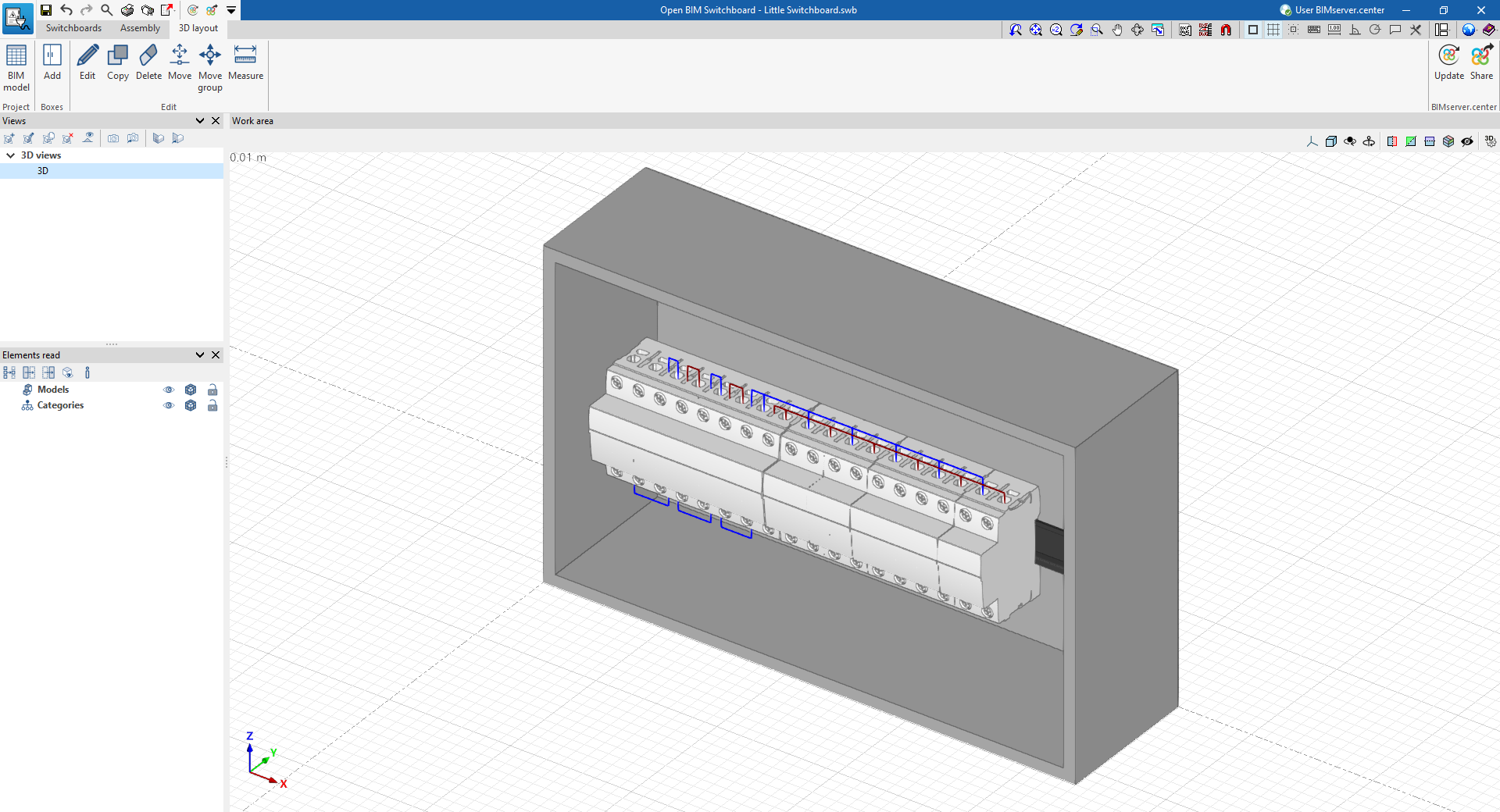
The "3D layout" tab has a work environment that allows the boxes defined in the previous tabs to be placed in the space.
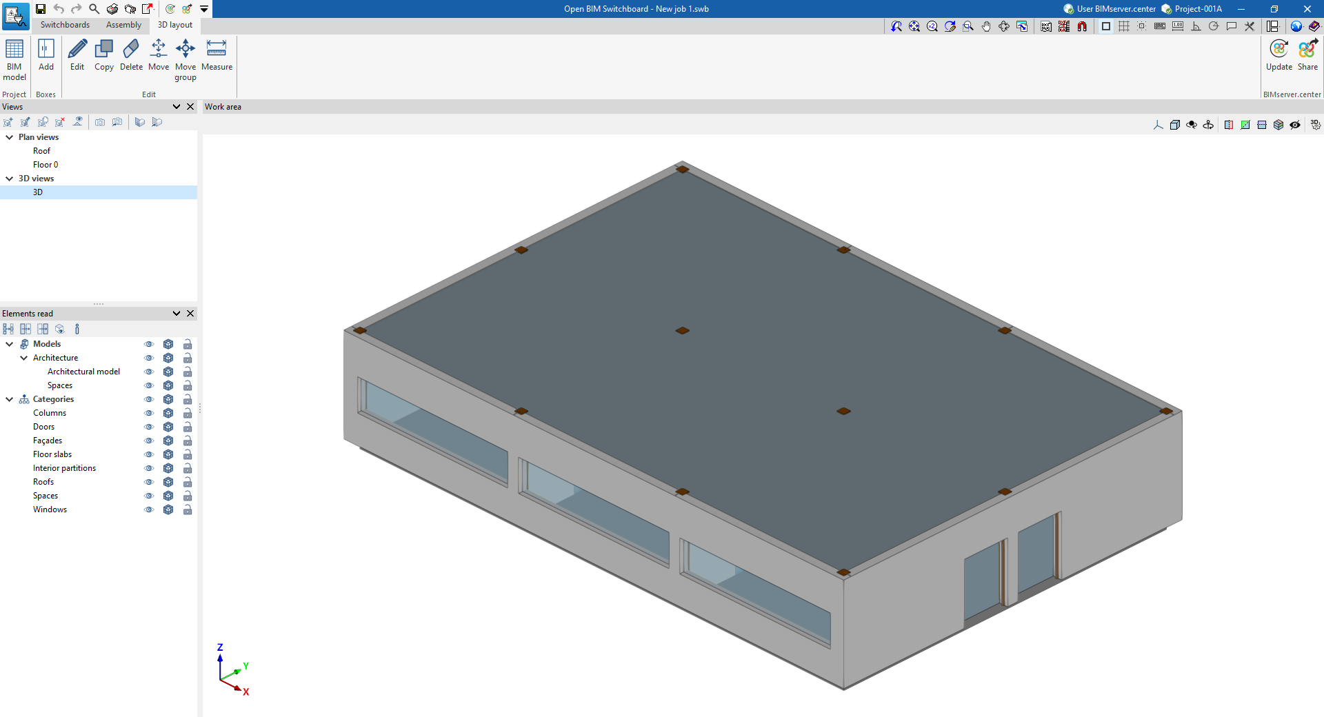
This tab displays the following:
- An upper toolbar where the tools for displaying the elements arranged in the model and the tools for adding the boxes in the work area are located. The editing tools are also located here.
- The work area, on the right of the screen, where the boxes associated with the electrical panels are entered and displayed in the space.
- On the left-hand side, several panels with tools for defining the project views and managing the visibility of the elements read from the BIM model.
Data input and output sequence for the design of electrical panels
The electrical panels in an electrical system can be designed in the program using the following sequence of data input and output:
- Creating a new project (from "File", "New").
- (Optional) Linking to BIMserver.center and importing BIM model data.
- Reviewing and/or defining electrical switchboards and their associated switchgear in the "Switchboards" tab:
- (Optional) Importing manufacturer catalogues (from "Project", "Catalogues").
- (Optional) Importing the electrical system project data from .txt or .csv files (via "Project", "Catalogues"), if data has not been imported from BIMserver.center.
- Automatically generating switchboards and switchgear (from "Switchboards", "Generate").
- (Optional) If data has not been imported from BIMserver.center or from .txt or .csv files, creating panels (using the options in the "Panels" section) and defining the associated switchgear for each panel (using the options in the "Switchgear" section) manually.
- Details on the installation of electrical panels can be found under the "Installation" tab:
- (Optional) Importing manufacturer catalogues (from "Project", "Catalogues").
- Defining bounding boxes for frames (options in the "Bounding Boxes" group).
- Adding rails, moulded box brackets, front plates and/or other fittings (options under the "Tracks", "Brackets", "Plates" and "Other fittings" sections).
- Laying out switchgear within the space (options in the "Switchgear" group).
- (Optional) Insertion of busbars (options in the "Busbars" group).
- (Optional) Drawing of bridge lines (options in the "Bridge lines" group).
- (Optional) Three-dimensional layout of the boxes in the model (options on the "3D Layout" tab).
- Accessing the drawings (from "File", "Drawings").
- (Optional) Generating the report and bill of quantities in BC3 format (via "File", "Reports"/"Export").
- (Optional) Exporting BIMserver.center (via "BIMserver.center", "Share").
Examples of electrical panel layouts
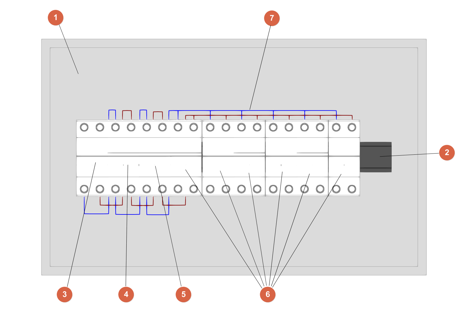
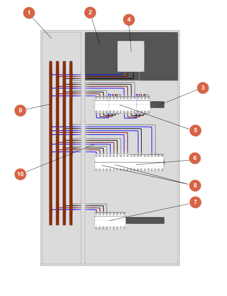
Below are examples of electrical panels that can be designed in the program, showing the layout of their components and the options (in the "Assembly" tab) that allow them to be added:
Domestic switchboard
- Modular box (from "Envelopes", "Add").
- Track (from "Tracks", "Add").
- Switch or control switch (from "Switchgear", "Track").
- Main circuit breaker (from "Switchgear", "Track").
- Residual current circuit breaker (from "Switchgear", "Track").
- Individual circuit breakers (from "Switchgear", "Track").
- Bridge lines (from "Bridge lines", "Add").
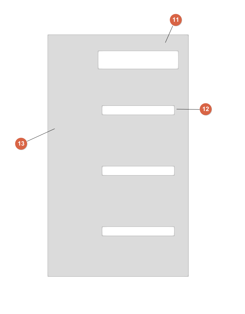
Main switchboard in an industrial building
- Configurable cabinet-style box (from "Envelopes", "Add").
- Moulded inner box insert (from "Inserts", "Add").
- Lanes (from "Lanes", "Add").
- Industrial circuit breaker in a moulded case (from "Switchgear", "Track").
- Residual current devices and circuit breakers for power take-off circuits (from "Switchgear", "Track").
- Residual current devices and circuit breakers for socket circuits and other applications (from "Switchgear", "Track").
- Residual current devices and circuit breakers for lighting circuits (from "Switchgear", "Track").
- Circuit breakers in the distribution boards for the warehouse and office circuits (from "Switchgear" and "Track").
- Busbars (from "Busbar", "Add").
- Bridge lines (from "Bridge lines", "Add").
- Front plate of the moulded case switch (from "Faceplates", "Add").
- Modular front plates (under "Panels", 'Add').
- Blind front panels (from "Panels", "Add").
Creating a new project, linking to a project and importing data
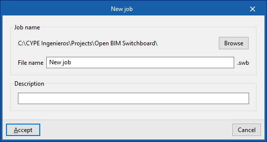
When you launch the app and click on "New", you are given the option to create a "New job". After entering the "File name" and "Description", the project can then be added to an existing project on BIMserver.center.
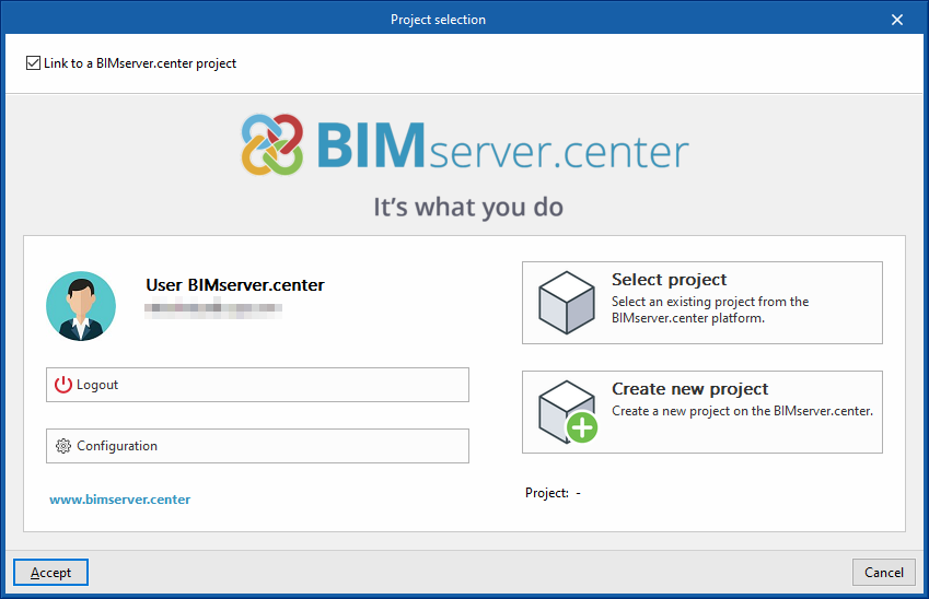
This is done in the "Project selection" window, which offers the following options:
- On the left-hand side, you can sign in using a BIMserver.center account.
- On the right-hand side, you will find the "Select project" option, which allows you to choose an existing project. You also have the option to "Create a new project". If you do so, the project you create will be visible on BIMserver.center from that point onwards.
- You have the option to start the project without linking it to the BIMserver.center platform. To do this, simply uncheck the box labelled "Link to a BIMserver.center project", located in the top-left corner.
Once the new project has been created, you will be taken to the program’s main interface. At any point thereafter, whilst working on the project, you can share or import project files via the “BIMserver.center” panel, located in the top-right-hand corner of the main interface.
Importing BIM models
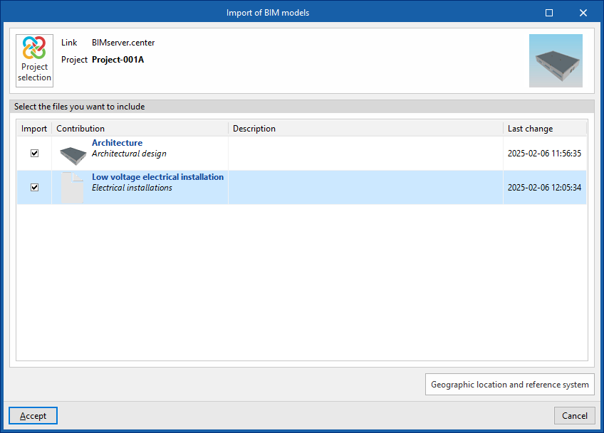
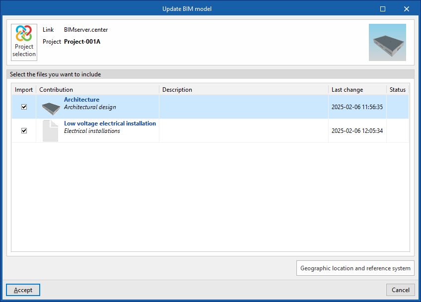
When creating a new project, if you have selected a project hosted on the BIMserver.center platform via "Select project", the "Import BIM models" window will appear, displaying the files contained in that project in IFC format.
To include the information from a specific project file, tick the "Import" box and confirm.
Import results
The program will incorporate the electrical project data extracted from the BIM model. You can then create switchboards and switchgear that correspond to the extracted data in the "Switchboards" tab, or generate them automatically.
In addition, the "3D layout" tab displays the 3D models included in the project, such as the building’s geometry. This allows you to position the enclosure or frame of each switchboard by using the other elements extracted from the models as reference points.
Options on the "Switchboards" tab
The "Switchboards" tab allows you to list the electrical switchboards included in the project and specify the switchgear for each one. To do this, you can import the electrical project data from other apps or enter the information directly from scratch.
The options in this tab are as follows:
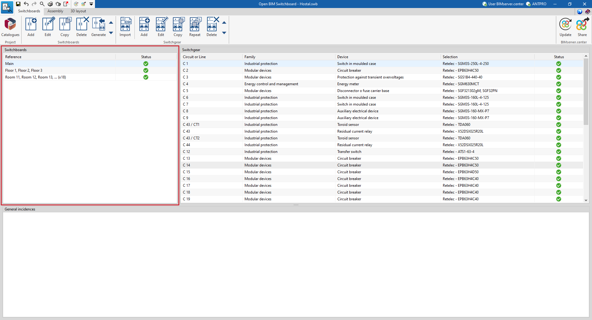
List of switchboards
The "Switchboards" panel on the left-hand side of the interface displays a list of the project's electrical switchboards, defined using the options described below. The following information is displayed for each panel:
- Reference
Reference to the table or tables in the group. - Status
Displays the status of the switchboard. Clicking on it displays any associated issues, if any.
List of switchgear
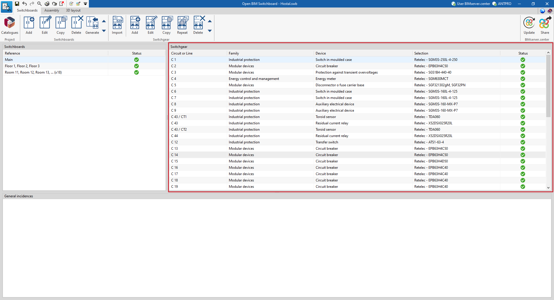
The "Switchgear" panel on the left-hand side of the interface displays a list of the devices configured using the options described below. The following information is displayed for each device:
- Circuit or line
The reference number of the circuit or line to which the device belongs. - Family
Device family. - Device
Device type. - Selection
Details of the selected device. - Status
Displays the device's configuration status. Clicking on it displays any associated issues, if there are any.
Issue management
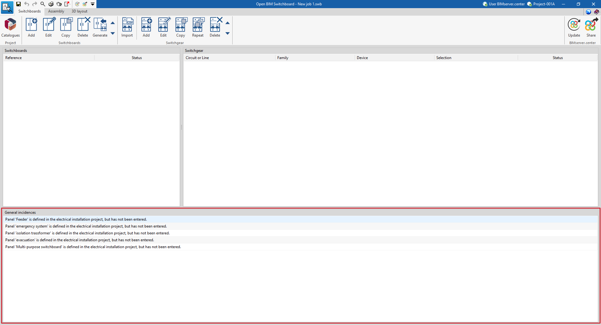
The "General issues" panel at the bottom of the interface displays the issues to be resolved that have been detected by the program.
Importing catalogues
In the "Project" section of the main toolbar, you will find the option to download manufacturer catalogues from the Open BIM Database:

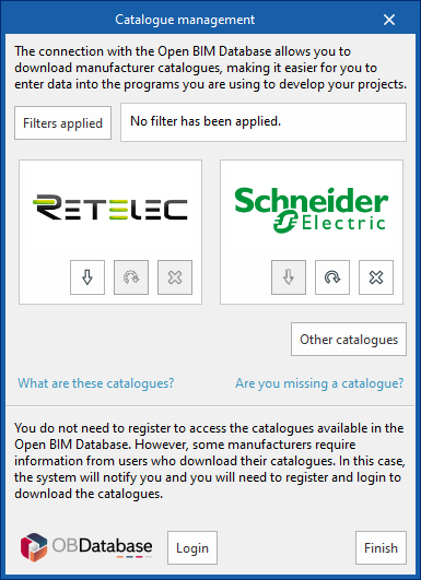
Clicking on this option opens a window showing the available manufacturer catalogues.
Download catalogues
The following options are displayed for each manufacturer:
- Download
Downloads the manufacturer’s catalogue. The products in the catalogue will be available in the project. - Update
Updates the catalogue for the selected manufacturer to the latest version, deleting the version previously downloaded to the project. - Delete
Deletes the selected manufacturer's catalogue. The products in the catalogue will no longer be available in the project.
Connecting to the Open BIM Database
At the bottom of this dialogue box, the program allows you to log in using an Open BIM Database account and password.
The products from the downloaded catalogues can be selected when defining the other elements.
Importing project data
In the "Project" section of the main toolbar, you will find the option that allows you to import data from electrical projects created in external programs using .txt or .csv files:

Creating and editing switchboards
The "Switchboards" section of the main toolbar contains options for managing the project's electrical switchboards, as well as generating them from imported data:

- Add
Adds a switchboard or group of switchboards to the list. - Edit
Edits the properties of the selected switchboards or group of switchboards in the list. - Copy
Copies the selected switchboards or group of switchboards to the list. - Delete
Deletes the selected switchboards or group of boxes from the list. - Generate
Generates a list of switchboards and the associated switchgear for each one based on information imported from the electrical design created in other applications.
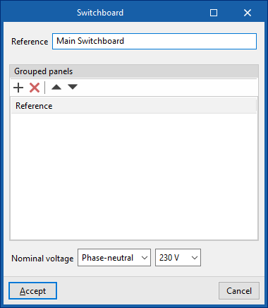
When adding a table, the program allows you to specify the following properties:
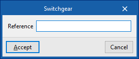
- Reference
Switchboards reference. - Grouped panels
If the project includes switchboards with the same specifications (for example, the electrical panels in the rooms of a hotel), entries can be made in this table using the reference number of each individual electrical panel. This allows you to define a group of identical panels. - Rated voltage
Defines the rated voltage of the switchboard ("Phase-to-phase" or "Phase-to-neutral").
If the file contains information from an electrical project created using other apps, the program provides wizards on the right-hand side that allow you to select one of the project panels directly.
Defining switchgear
The "Switchgear" section of the main toolbar contains options for managing the switchgear associated with each of the defined switchboards, as well as for importing data from .csv files:

- Import
Imports devices from a .csv file. - Add
Adds the selected device to the list. - Edit
Edits the properties of the device selected from the list. - Copy
Copies the device selected from the list once. - Repeat
Copies the selected elements in the list a specified number of times. - Delete
Removes the selected device from the list.
When adding each switchgear device, the reference for the "Circuit or line" to which it belongs is specified. You can define a "Generic" element or use one of those available in the "Manufacturer catalogues".
In addition, you must specify the "Family" and the type of "Device":
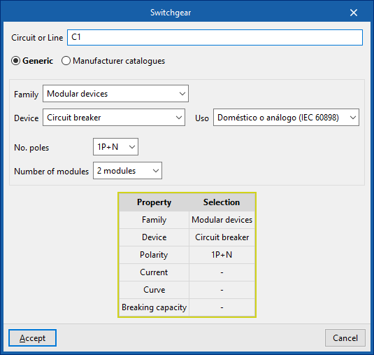
The devices available for each family are listed below:
Family: Modular switchgear
Devices:
- Circuit breaker
- Residual current circuit breaker
- Combined circuit breaker + residual-current device protection
- Combined circuit breaker + permanent overvoltage protection
- Combined circuit breaker + transient and permanent overvoltage protection
- Auxiliary electrical device
- Protection against transient overvoltages
- Switch or linear switch
- Light indicators
- Modular contactor or impulse relay
- Modular contactor or remote-controlled contactor
- Protection against electric arcs
- Disconnector of the fuse carrier base
- Remote control. Intelligent protection of installations
- Time regulation
- Control relays
Category: Industrial protection
Devices:
- Magnetic starter
- Auxiliary electrical device
- Switch in moulded case
- Residual current relay
- Transfer switch
- Contactor or miniature contactor
- Disconnector to interrupt lines
- Toroid sensor
Category: Solar shading
Devices:
- Circuit breaker
- Protection against transient overvoltages
- Disconnector or fuse carrier base
Category: Energy monitoring and management
Devices:
- Network analyser
- Energy meter
- Current transformer
Options on the "Assembly" tab
The "Assembly" tab allows you to display a graphical representation of the enclosures, components and layout of the switchgear for the electrical panels previously defined in the file.
The options on this tab are as follows:
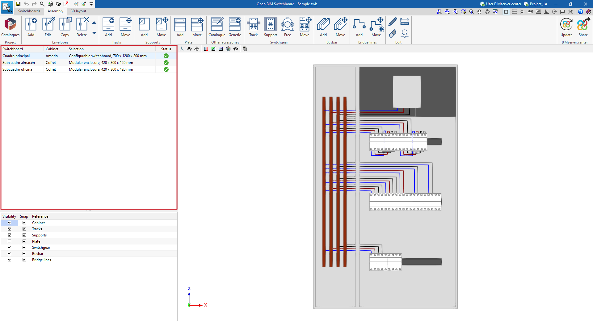
List of envelopes
The left-hand side of the interface displays a list of the enclosures defined using the options described below. The following information is shown for each box:
- Frame
Reference number of the frame associated with the box. - Box
Box reference. - Selection
Details of the selected box. - Status
Displays the status of the box. Clicking on it displays any associated issues, if there are any.
The box selected from the list will be displayed in the main workspace, in the centre of the interface.
Visibility and snapping options
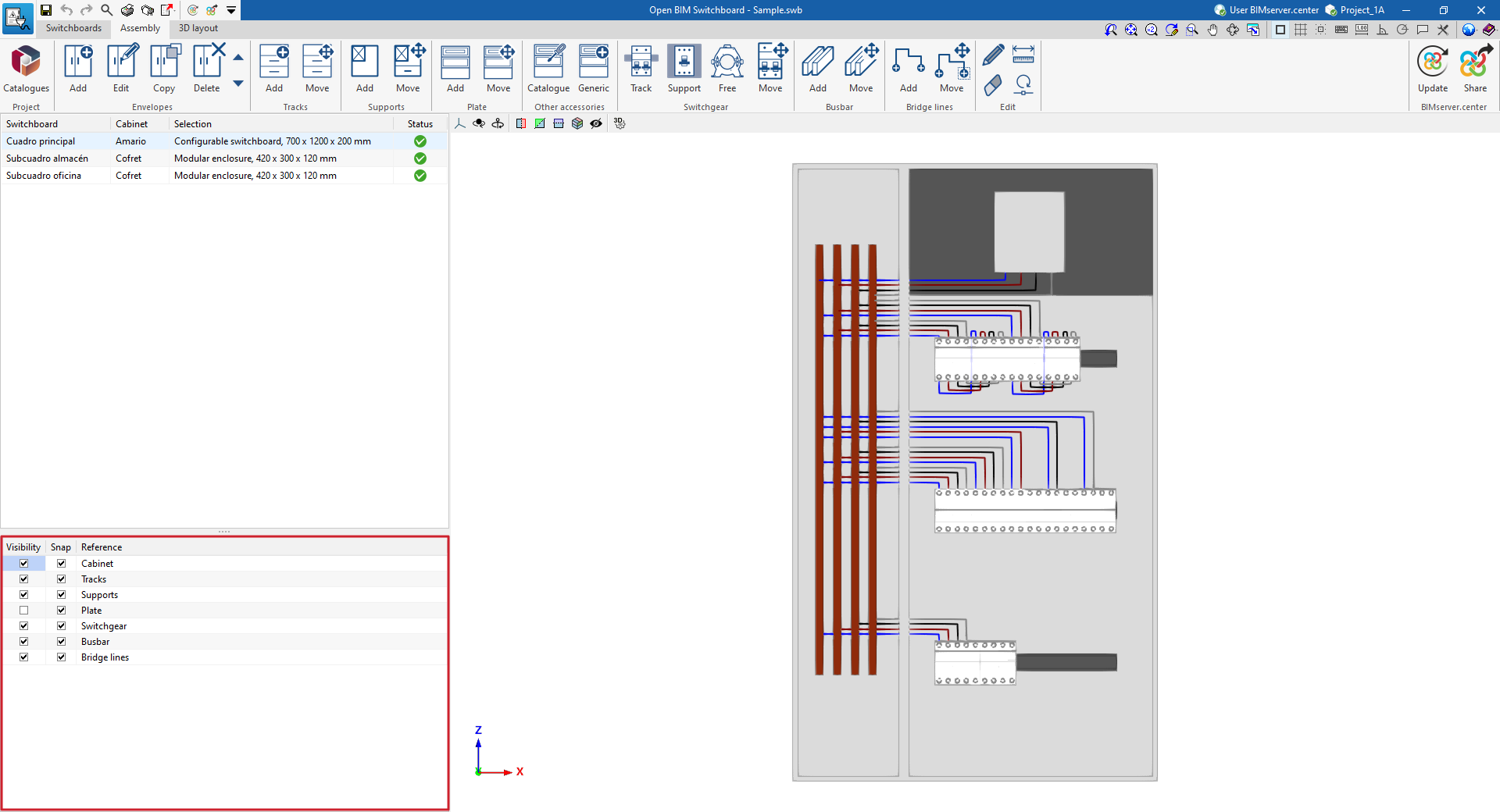
The panel at the bottom of the left-hand side allows you to control the "Visibility" of the elements added by category, as well as the option to "Snap" them when using the element insertion and drawing tools.
Importing catalogues
In the "Project" section of the main toolbar, you will find the option that allows you to download manufacturer catalogues via the connection to the Open BIM Database, making it easier to enter data into the program for project development:

Clicking on this option opens a window showing the available manufacturer catalogues.
Download catalogues
The following options are displayed for each manufacturer:
- Download
Download the manufacturer’s catalogue. The products in the catalogue will be available in the project. - Update
Updates the catalogue for the selected manufacturer to the latest version, deleting the version previously downloaded to the project. - Delete
Deletes the selected manufacturer's catalogue. The products in the catalogue will no longer be available in the project.
Connection to the Open BIM Database
At the bottom of this dialogue box, the program allows you to log in using an Open BIM Database account and password.
The products from the downloaded catalogues can be selected when defining the other elements.
Creating and editing envelopes
The "Envelopes" section of the main toolbar contains the options for defining the envelopes or enclosures for the project's electrical panels:

- Add
- Edit
- Copy
- Delete
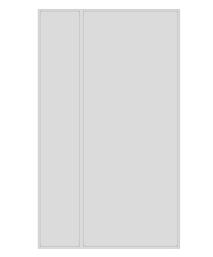
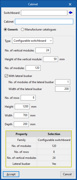
When adding enclosures, if frames have been entered in the "Switchboards" tab, the wizard allows you to import their reference using the wizard on the right-hand side to link them to the enclosure being added. When doing so, you can choose to "Show only those frames that do not include any boxes" (to add boxes to frames that do not yet have them) or "Show all panels, including those that do not include a case".
You can define a "Generic" item or use one of those available in the "Manufacturer catalogues". In the latter case, you can perform an "Automatic selection" from the downloaded catalogues using the relevant option.
Inserting tracks, brackets, plates and other fittings
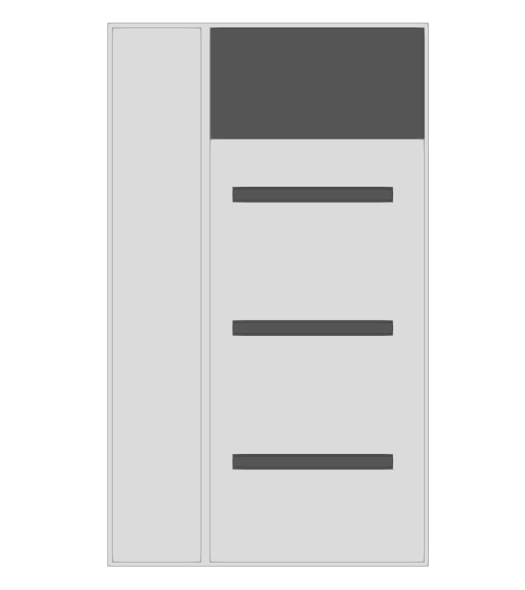
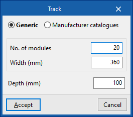
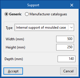
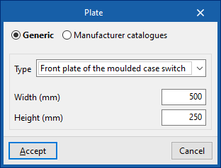
The following sections of the main toolbar contain the options for adding tracks, supports, plates and other fittings to each of the enclosures or boxes selected in the list above:

- "Tracks" section
- Add
- Move
- "Supports" section
- Add
- Move
- "Plates" section
- Add
- Move
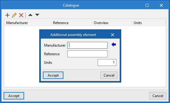
- "Other fittings" section
- Catalogue
- Generic
You can define a "Generic" element or use one of those available in the "Manufacturer catalogues".
Each of these elements can be placed on the panel in the main workspace, located in the centre of the interface.

Inserting switchgear
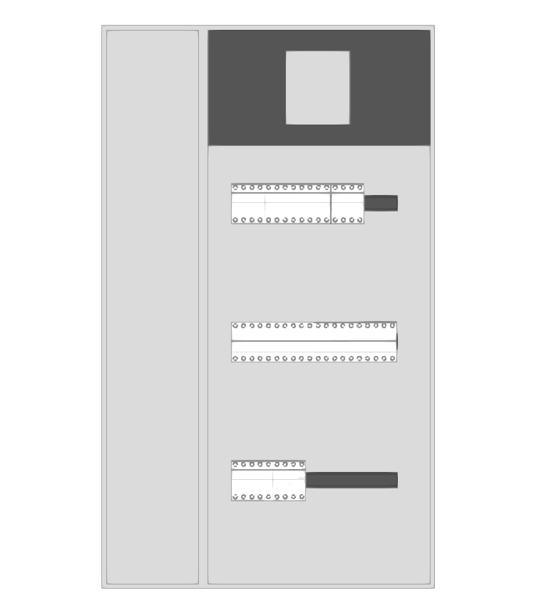
In the "Switchgear" section of the main toolbar, you will find the options that allow you to place the devices for each of the project’s switchboards in their correct positions:

- Track
Position a predefined track. - Support
Positions a predefined support. - Free
Positions a device freely within the panel. - Move
Moves a previously selected device.
Each device can be positioned in the main workspace, located at the centre of the interface, in the corresponding switchboard, track or support that has been previously defined.
Installing busbars and bridge lines
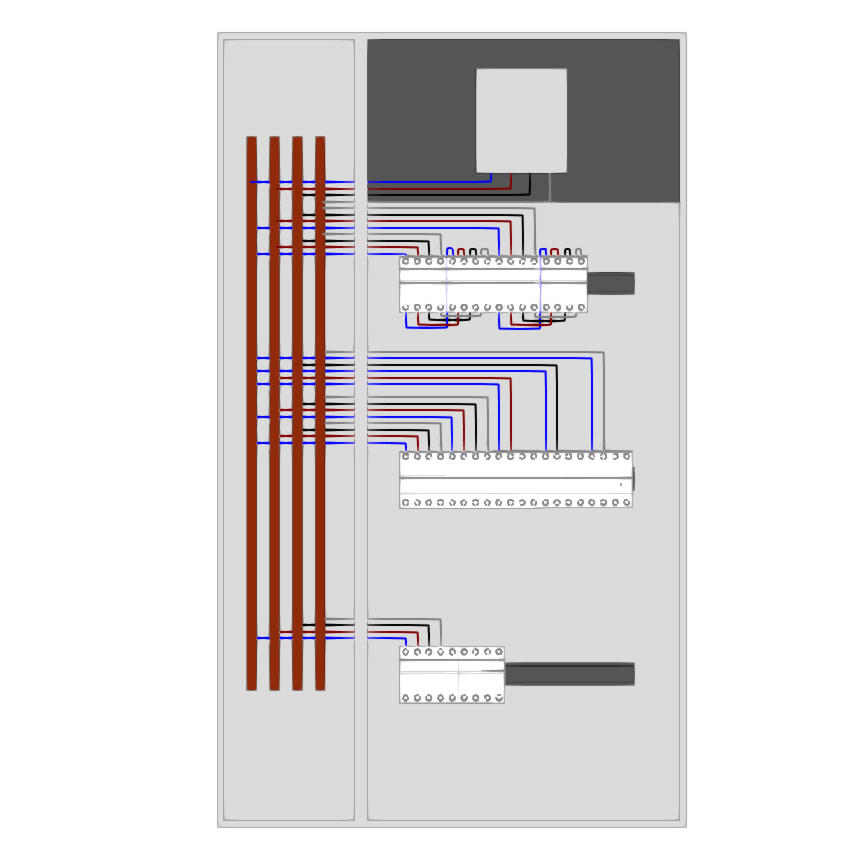
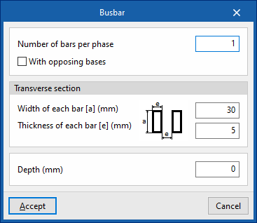
The following sections of the main toolbar contain the options for adding busbars or bridge lines between devices and busbars in each of the enclosures or boxes selected in the list above:

- "Busbars" section
- Add
- Move
- "Bridge Lines" section
- Add
- Move
Each of these elements can be placed in the main workspace, located in the centre of the interface.

Editing tools
The "Edit" panel provides the following tools for editing the elements displayed in the workspace:

- Edit
Edits the settings for the selected element. - Delete
Deletes the selected element. - Measure lengths
Measures the distance and area between the selected points. - Rotate
Rotates elements that can be rotated.
Options on the "3D layout" tab
The "3D layout" tab provides an environment in which the user can position the spaces of the electrical panels defined in the other tabs in their actual spatial orientation. To do so, the user can use other models included in the BIM project as a visual reference.
The options on this tab are as follows:
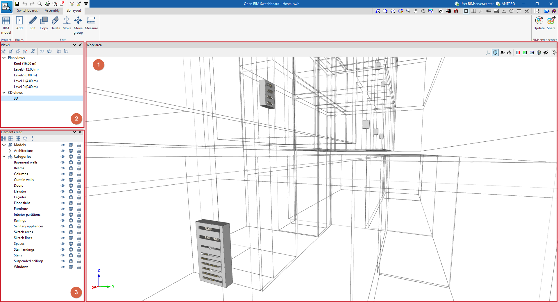
Work area
The work area (1), located in the centre of the interface, displays the selected view of the model and allows you to place the frames in the space.
At the top, there are options for entering elements into the work area, which appear on the left when adding envelopes to the model, and tools for controlling the visibility of the 3D model, on the right.
Managing views
The "Views" panel (2) in the top-left corner allows you to create and manage views of the model, whether 3D or 2D (such as floor plans, sections or elevations).
This tool is also available in other CYPE programs. Further information can be found via the following link.
Managing read elements
The "Read elements" panel (3) in the bottom-left corner allows you to view and snap the elements that have been read in the other models included in the BIM project.
Like the previous one, this tool is available in other CYPE programs. Further information can be found via the following link.
| Note: |
|---|
| Switchboards imported into programs such as CYPELEC Distribution can be viewed here as generic 3D elements. In this way, just like the other elements extracted from the BIM project models, they can serve as a spatial reference for positioning the detailed enclosures in Open BIM Switchboard, which take into account the switchboard’s actual dimensions. |
Layout of boxes on the model
Boxes are arranged on the model using the options in the top toolbar:

"Project" section
- BIM model
Display and edit the position coordinates and orientation of the boxes in the model.
"Boxes" section
- Add
Select one of the boxes still to be placed in the model, specifying the reference numbers for the "Panel" and the "Box", and then position it in the workspace.
"Edit" section
The "Edit" panel provides the following tools for editing the boxes in the model:
- Edit
Edit the settings for the selected element. - Copy
Make a copy of the selected element. - Delete
Delete the selected element. - Move
Move an element. - Move group
Move the selected group of elements. - Measure
Measure the distance and area between the selected points.
Results output
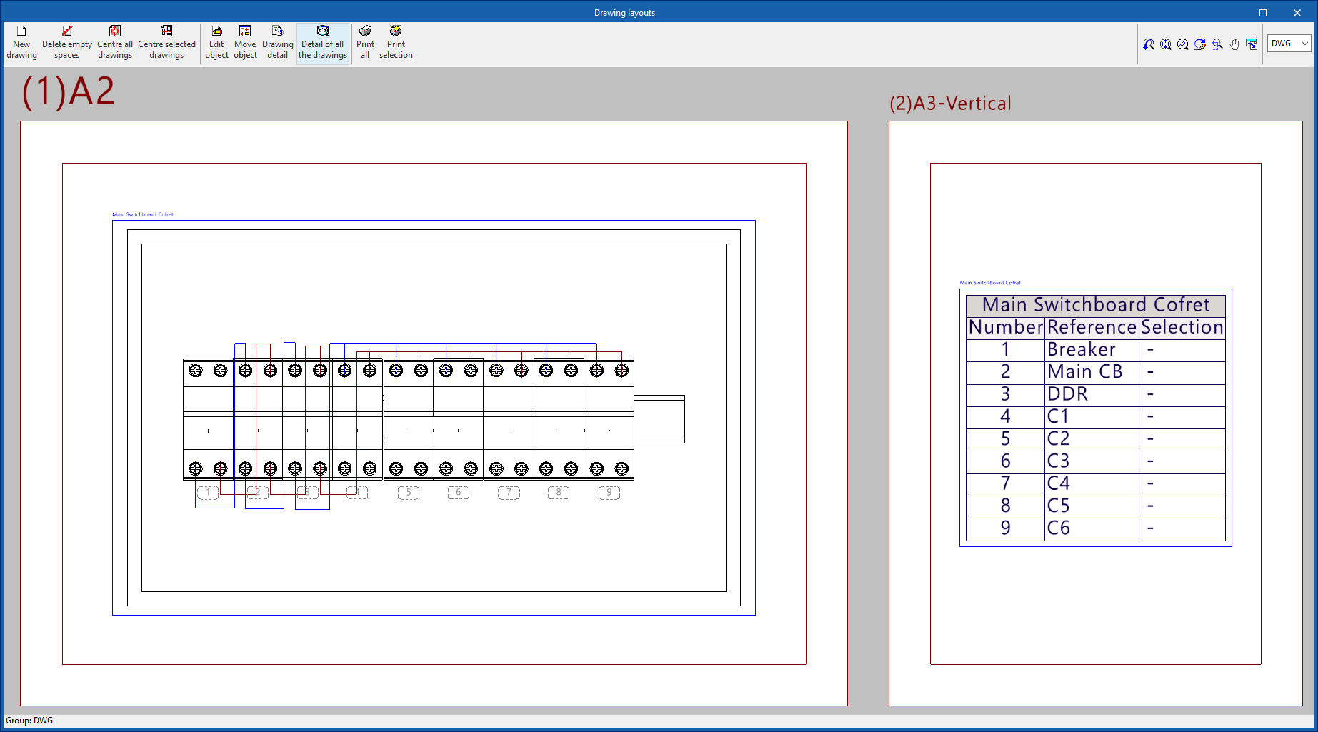
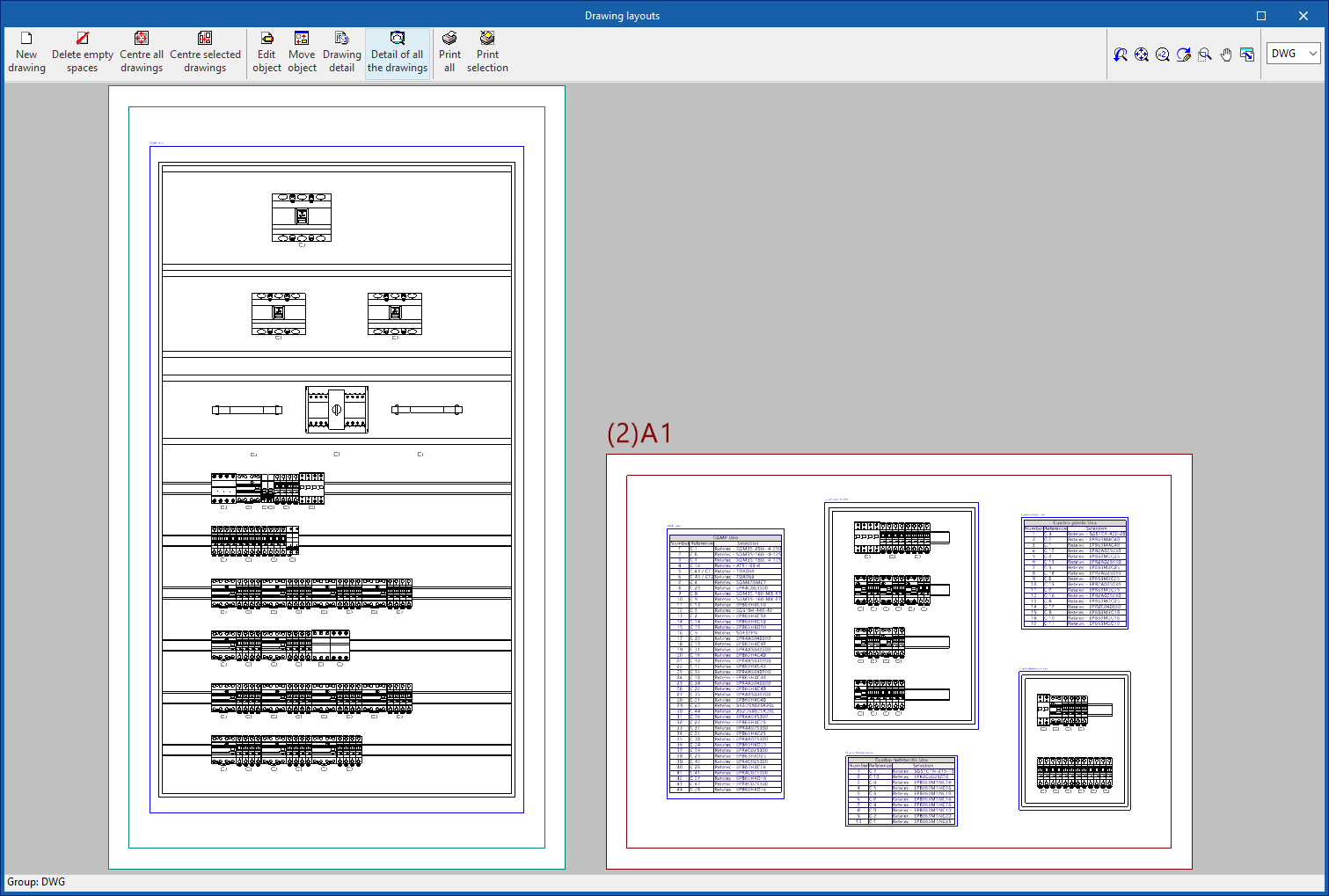
Drawings in DWG, DXF or PDF format
The program can print the drawings of the electrical panels defined in any graphic peripheral device configured in the computer or create .dwg, .dxf or .pdf files.
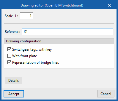
The following parameters can be configured by editing the drawing:
- Scale
- Reference
- Configuración del plano
- Switchgear tagsm with key (optional)
- With front plate (optional)
- Representation of bridge lines (optional)
- Details
Drawings can be obtained via the "Drawings" option at the top of the interface or via the "Drawings" option in the "File" menu.
Bill of quantities in BC3 format and bill of quantities report
If price information is available for the elements that make up the tables, the following documents can be obtained from the program:
- Exporting the budget in FIEBDC-3 (BC3) format (via the "Export" option at the top of the interface or from the "File" menu).
- Bill of quantities report in HTML, PDF, TXT, RTF or DOCX format (via the "Reports" option at the top of the interface or from the "File" menu).
GLTF file compatible with BIMserver.center
When a project is exported to the BIMserver.center platform, a 3D model is automatically exported in GLTF format for the integration of the installation model in the Open BIM project, allowing its visualisation:
- on the online platform;
- in the BIMserver.center app for iOS and Android;
- in virtual reality and augmented reality;
- in other CYPE programs.
Integration into the BIMserver.center platform
Many of CYPE's programs are connected to the BIMserver.center platform and allow collaborative work to be carried out via the exchange of files in formats based on open standards.
Please note that, to work on BIMserver.center, users can register on the platform free of charge and create a profile.
When accessing a program connected to the platform, the program connects to a project in BIMserver.center. This way, the files of the projects that have been developed collaboratively in BIMserver.center are kept up to date.

| More information: |
|---|
| For further details related to using CYPE software via the BIMserver.center platform, please click on this link. |
Options available in Open BIM Switchboard
The “BIMserver.center” section of the main toolbar contains the features needed to use the program alongside other BIMserver.center tools:

Updating
Updates the information contained in the files previously imported into the project, or import new files if required.
To do this, select the files you wish to include from the top section.
Sharing
Exports the installation data generated by the program to BIMserver.center so that you can share it with other users.
During the export process, you can specify the details relating to the IFC file to be exported:
- Name
- Description