
Options on the "3D layout" tab
The "3D layout" tab provides an environment in which the user can position the spaces of the electrical panels defined in the other tabs in their actual spatial orientation. To do so, the user can use other models included in the BIM project as a visual reference.
The options on this tab are as follows:
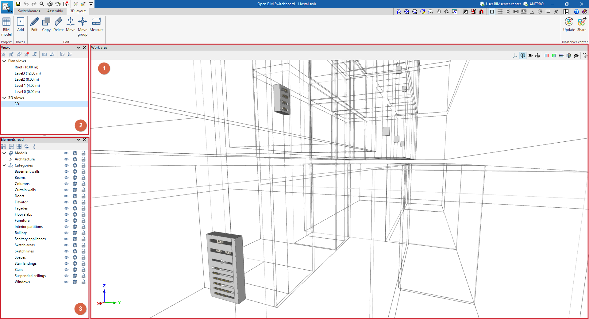
Work area
The work area (1), located in the centre of the interface, displays the selected view of the model and allows you to place the frames in the space.
At the top, there are options for entering elements into the work area, which appear on the left when adding envelopes to the model, and tools for controlling the visibility of the 3D model, on the right.
Managing views
The "Views" panel (2) in the top-left corner allows you to create and manage views of the model, whether 3D or 2D (such as floor plans, sections or elevations).
This tool is also available in other CYPE programs. Further information can be found via the following link.
Managing read elements
The "Read elements" panel (3) in the bottom-left corner allows you to view and snap the elements that have been read in the other models included in the BIM project.
Like the previous one, this tool is available in other CYPE programs. Further information can be found via the following link.
| Note: |
|---|
| Switchboards imported into programs such as CYPELEC Distribution can be viewed here as generic 3D elements. In this way, just like the other elements extracted from the BIM project models, they can serve as a spatial reference for positioning the detailed enclosures in Open BIM Switchboard, which take into account the switchboard’s actual dimensions. |
Layout of boxes on the model
Boxes are arranged on the model using the options in the top toolbar:

"Project" section
- BIM model
Display and edit the position coordinates and orientation of the boxes in the model.
"Boxes" section
- Add
Select one of the boxes still to be placed in the model, specifying the reference numbers for the "Panel" and the "Box", and then position it in the workspace.
"Edit" section
The "Edit" panel provides the following tools for editing the boxes in the model:
- Edit
Edit the settings for the selected element. - Copy
Make a copy of the selected element. - Delete
Delete the selected element. - Move
Move an element. - Move group
Move the selected group of elements. - Measure
Measure the distance and area between the selected points.
