
Shear wall drawings
StruBIM Shear Walls includes tools that can be used to automatically or manually generate drawings of shear walls designed in StruBIM. These drawings include sections, elevations and details, facilitating the graphic documentation of the designs.
The types of drawings generated are:
- Diagram
General representation of the sections, indicating the outer contour of the section, the start-finish direction of the segments, their reference to the thickness and the symbol of the direction of the elevation view. - Elevation
Elevation view of the walls of each of the segments. The reinforcement is shown from plan to plan. - Section
Detailed view, for a particular plan, of the entire section of the wall, with all segments and their reinforcement labelled. - Segment
Individual graphical detail of each wall segment in the section.
Access to the sheet editor
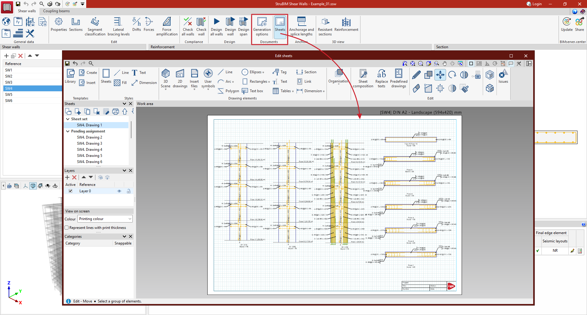
When clicking on the “Sheets” icon in the "Documentation" group, the sheet editor of the selected wall is opened.
The first time you access this section, the program asks whether the predefined composition of sheets is to be generated automatically. The representation of each sheet depends on the configuration previously selected in "Generation options".
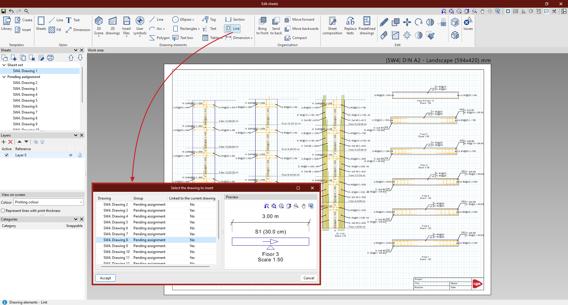
The contents can be rearranged using the "Link" option in the "Drawing elements" group, and other drawings can be inserted from "2D drawings" in the same group.
Configuration of the sheet representation
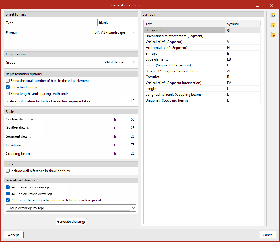
In the "Generation options" dialogue box, the following can be defined:
- Sheet format
Defines the format of the generated sheets:- With the "Type" option, a sheet can be selected to apply the associated format to the sheet.
- The "Empty" option can be used to manually define the format of the sheet.
- Organisation
Determines the group of sheets into which the generated sheets will be inserted. - Representation options
This section contains the following options:- Shows total number of bars in edge elements:
- When enabled, the reinforcement tags for edge elements show the total number of vertical bars (e.g., 14 #10). When disabled, the number of layers and the number of bars per layer are shown (e.g., 2x7 #7).
- Shows bar length:
- Adds the length of the bars to the labels of the horizontal bars.
- Shows lengths and spacings with units.
- Multiplier factor for the display size of the cross-section of the bars.
- Scales
- Scale divider for drawing section diagrams, section details, segment details, elevations and coupling beams.
- Tags
- Includes the wall reference in the title of the drawings.
- Predefined drawings of walls
- Indicates that the predefined wall drawings include section or elevation drawings.
- Represents sections with a detail for each segment:
- Users can choose between two representation modes. If the option is disabled, the entire section is shown with all its reinforcement. If enabled, a general diagram of the section is presented along with specific details for each segment.
- Users can define whether one drawing is shown per sheet or whether they are grouped according to type.
- Symbols
- Defines the symbols or abbreviations used in texts, notes, and clarifications that appear on tags.
Generation of predefined sheets
The automatic generation of the sheets can be carried out when accessing the "Sheets" section for the first time or within it, from the "Predefined sheets" option. According to the settings established in "Generation options", the program generates the drawings of the sections and elevations, together with the reinforcement tags.
In the elevations, the reinforcement of the edge elements is represented in detail, drawing all the horizontal and vertical reinforcement, while the distributed reinforcement is represented schematically, by means of a bar and arrows representing the area where this bar would be distributed.
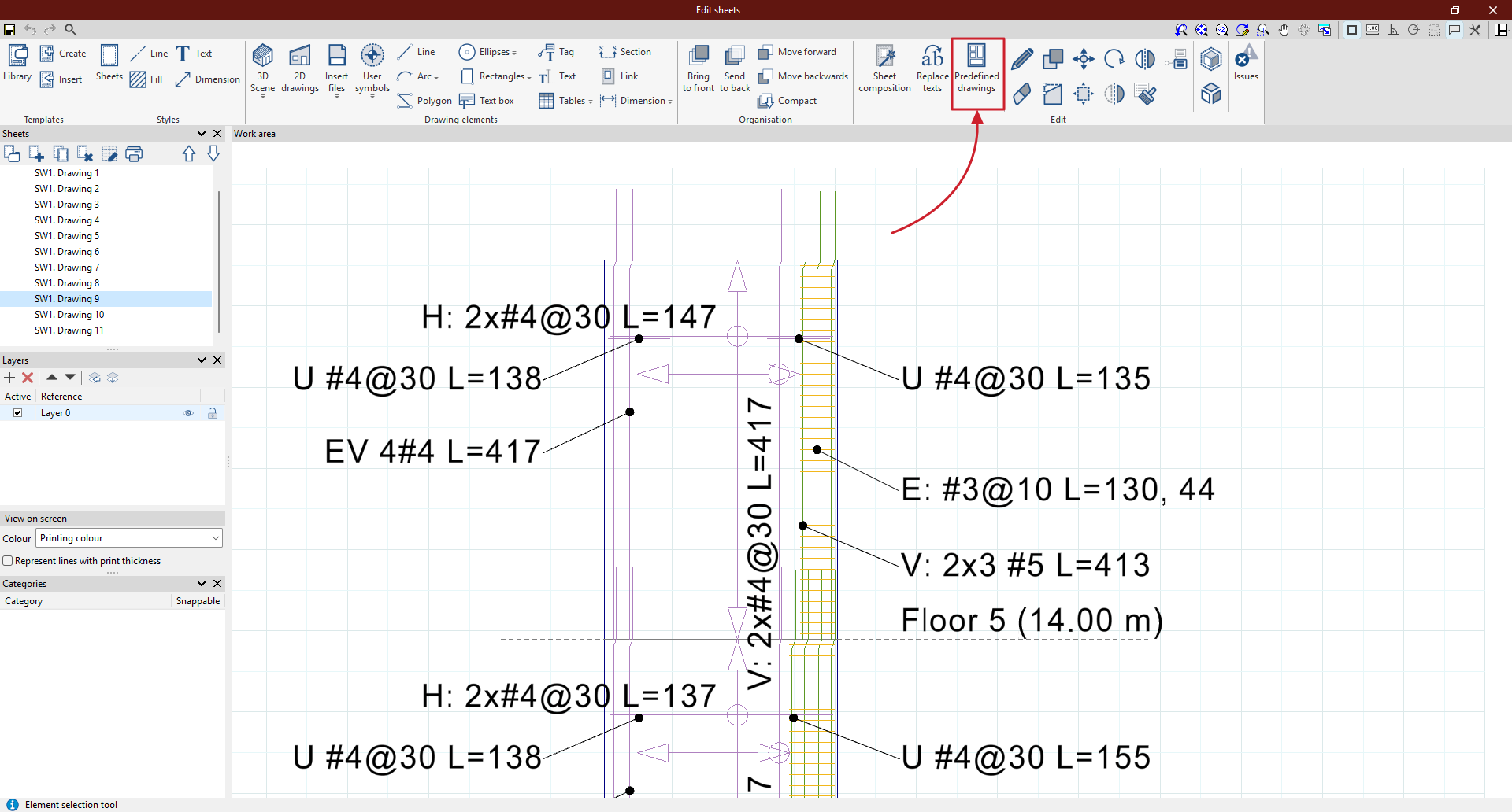
In the sections, each reinforcement block of each segment is represented in the plan with a tag. In addition, tags are included for the transverse reinforcement bars of the connections, such as U-bars or L-bars, if they have been defined.

| More information: |
|---|
| The work environment of the sheet editor is similar to the one in CYPE Connect, whose detailed information is available in the following link. This sheet editor is also integrated in other programs, such as StruBIM Steel or CYPE Architecture. |