Sheet editor work environment
The work environment of the "Sheet editing" window is similar to that of other CYPE modelling tools and has a system of dockable windows that can be customised to adapt the workspace to the needs of the project.
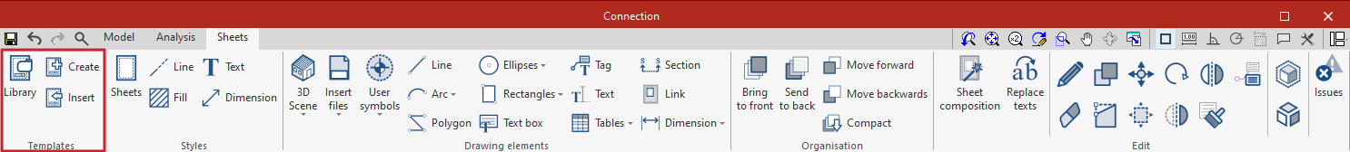
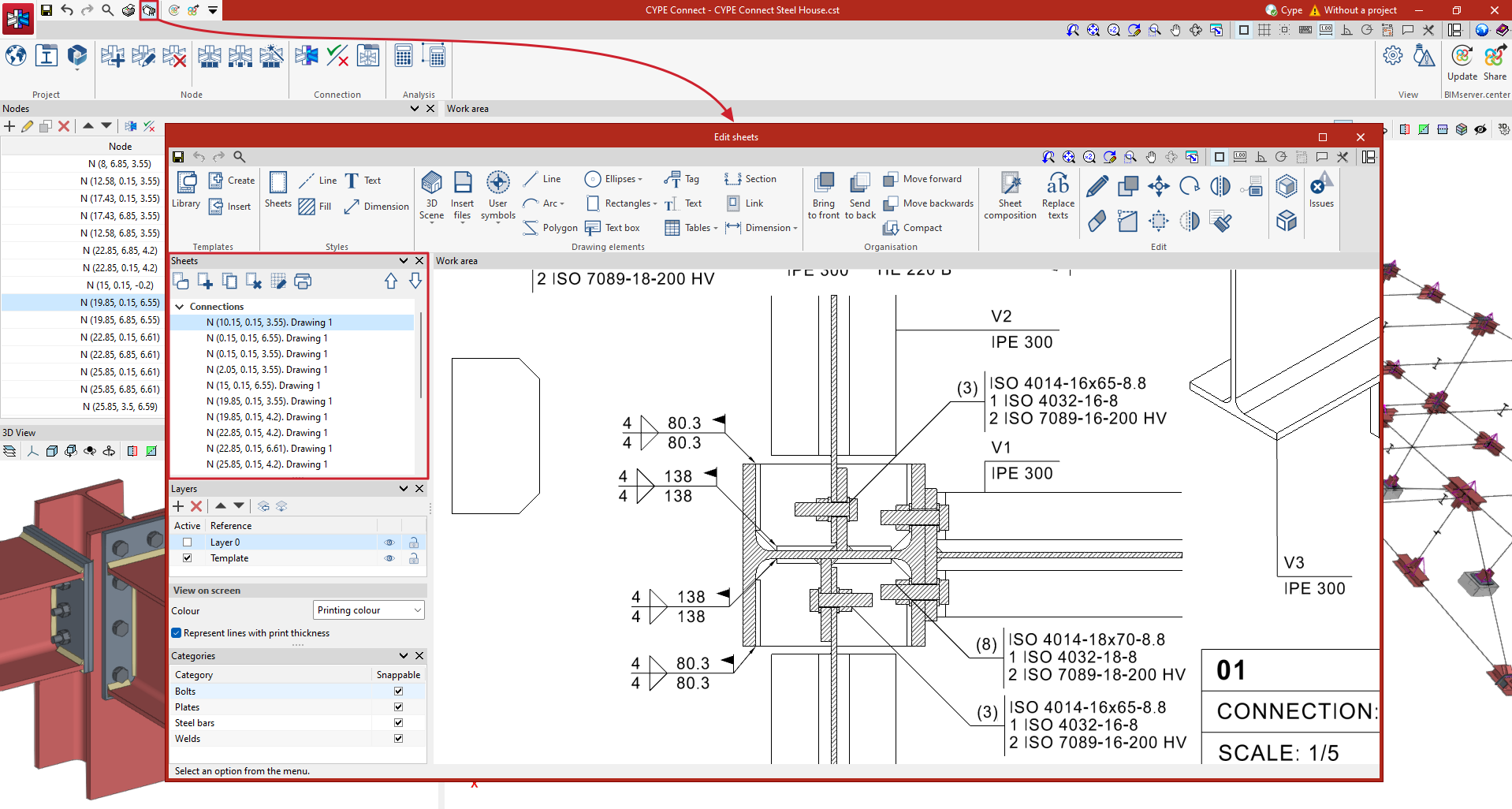
The interface is divided into 3 main parts: the top toolbar, the sidebar and the work area.
The toolbar contains different features. Here, users can create and manage templates, edit styles, and enter, edit or order drawing elements, among other options.
The work area is located on the right side of the screen and displays the composition of the individual sheets.
On the left-hand side are the main tools for managing the sheets and layers of the project. In addition, from the "View on screen" section, users can select the way they want to display the thickness and colour of the elements.
Managing and creating sheets
The "Edit sheets" window offers various options to make the management of sheets easier. Among the actions available are the possibility of creating groups, creating new sheets, copying existing sheets and deleting sheets already created.
Within the "Grid" option the visibility of the grid can be controlled. Users can select the colour of the main and secondary lines, and even adjust their spacing and division.
Furthermore, within this same section, there is a printing option, which generates PDF, DWF or DFX versions of the sheets created.
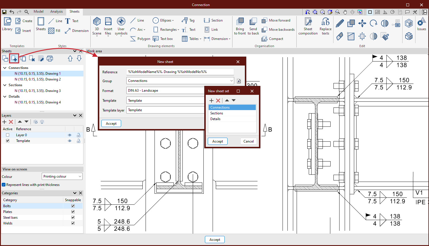
To start working, first of all, a new sheet must be created. To do this, select the desired standard paper size to represent the drawing, assign a name to the sheet and add it to a group if necessary. If a previously created template is available, it can be loaded into the program.
The sheet shall be drawn on the interface, and its size shall be indicated at the top right of the interface.
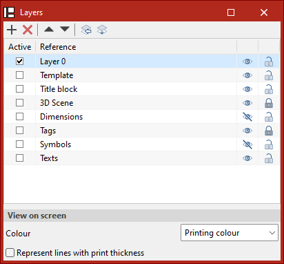
Managing and creating layers
From the "Layers" section, the elements of the sheet can be arranged as required, creating, deleting or relocating layers.
Different layers can be generated, which allow the work to be carried out in a systematic and organised way, considering elements such as views, surfaces, dimensions and titles, among others.
To create a new layer, click on the "Add" button, located on the left margin of the layer management section.
The layers of imported DWG or DXF elements can be managed by clicking on the "Layers of inserted DXF or DWG files" icon.
From the "Assign to layers" icon, the objects on the layers can be changed.
Users can select the active layer, as well as manage the visibility or choose whether the elements of that layer are snappable.
The elements can be displayed on the screen with their colour for printing, or with their identifying colour. The lines can also be displayed with their thickness for printing.
Creating and managing templates
From the "Sheets" tab, templates can be created or imported, which saves drawing time by being able to reuse the templates in future projects. Example templates provided can also be used.
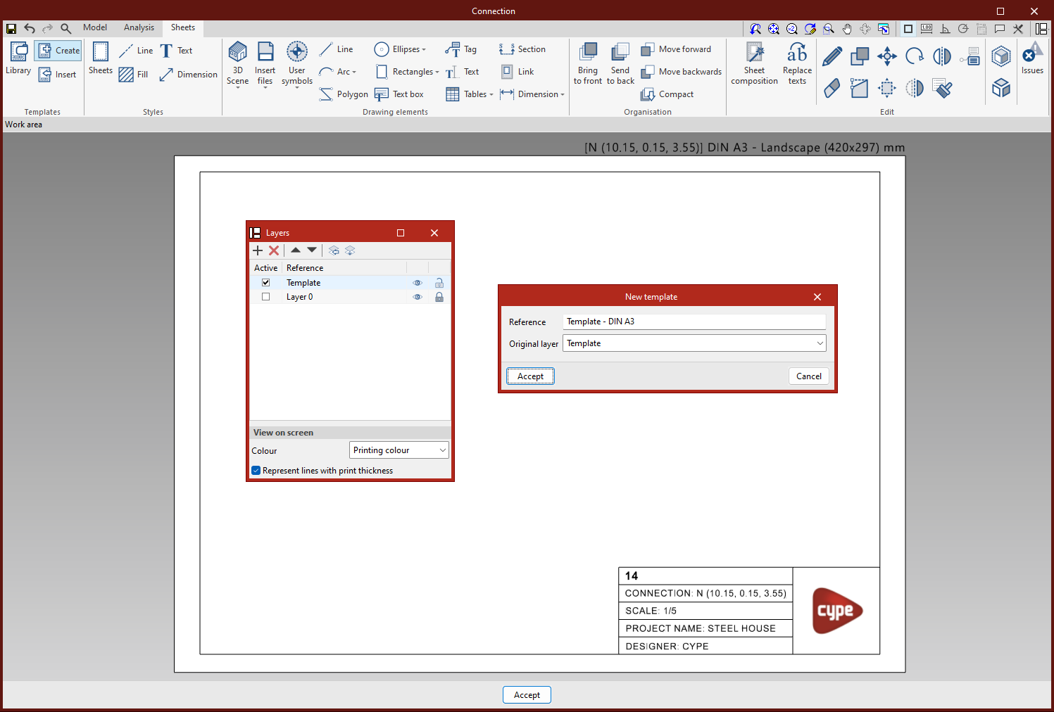
Create template
A template is made up of drawing elements: lines, texts, images, etc.
This is created from a layer in the "Layers" panel of the sidebar.
To create a template, all drawing elements must be entered on the same layer, click on "Create" and choose the reference name of the template and the layer on which the template was drawn to be loaded into the "Library".
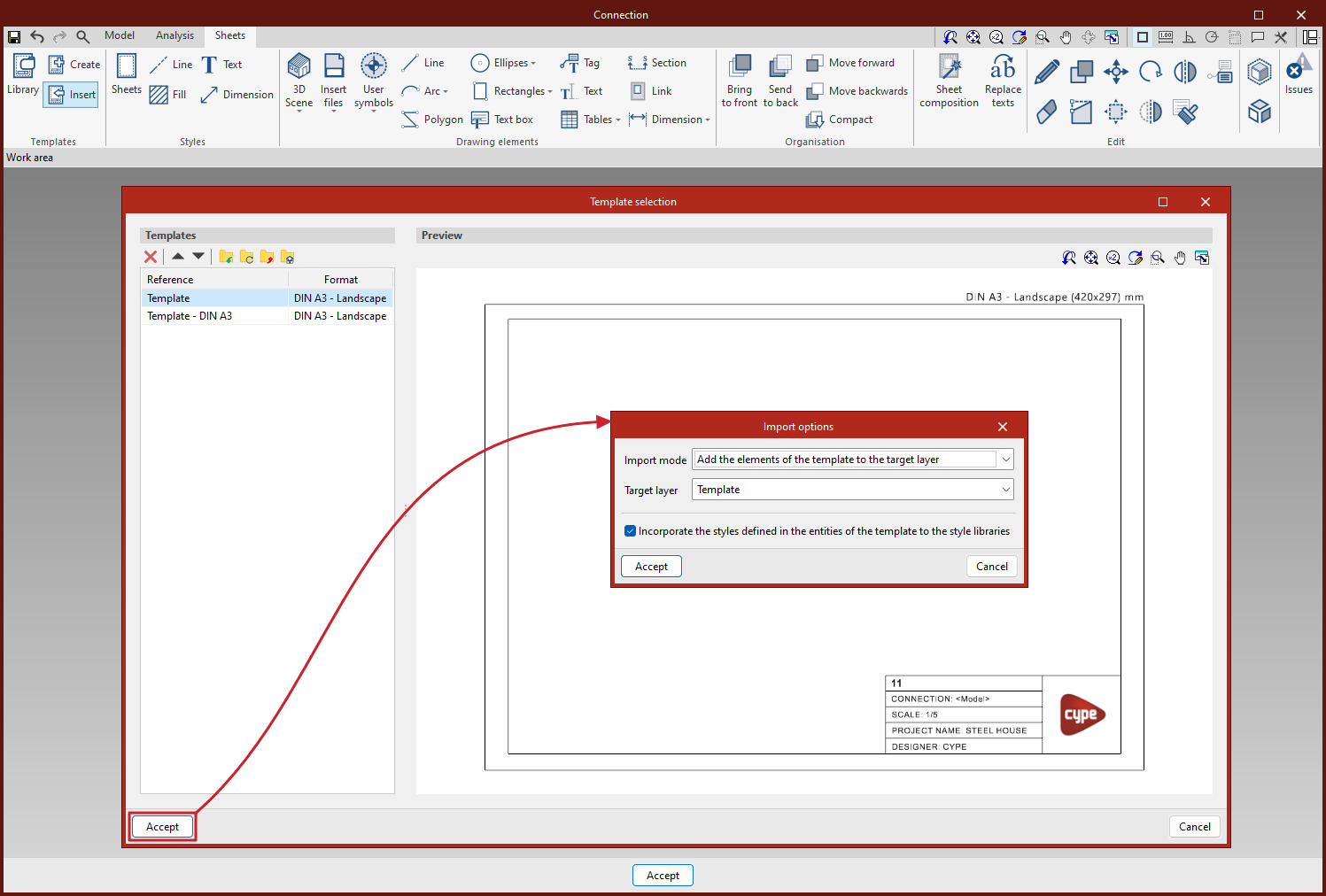
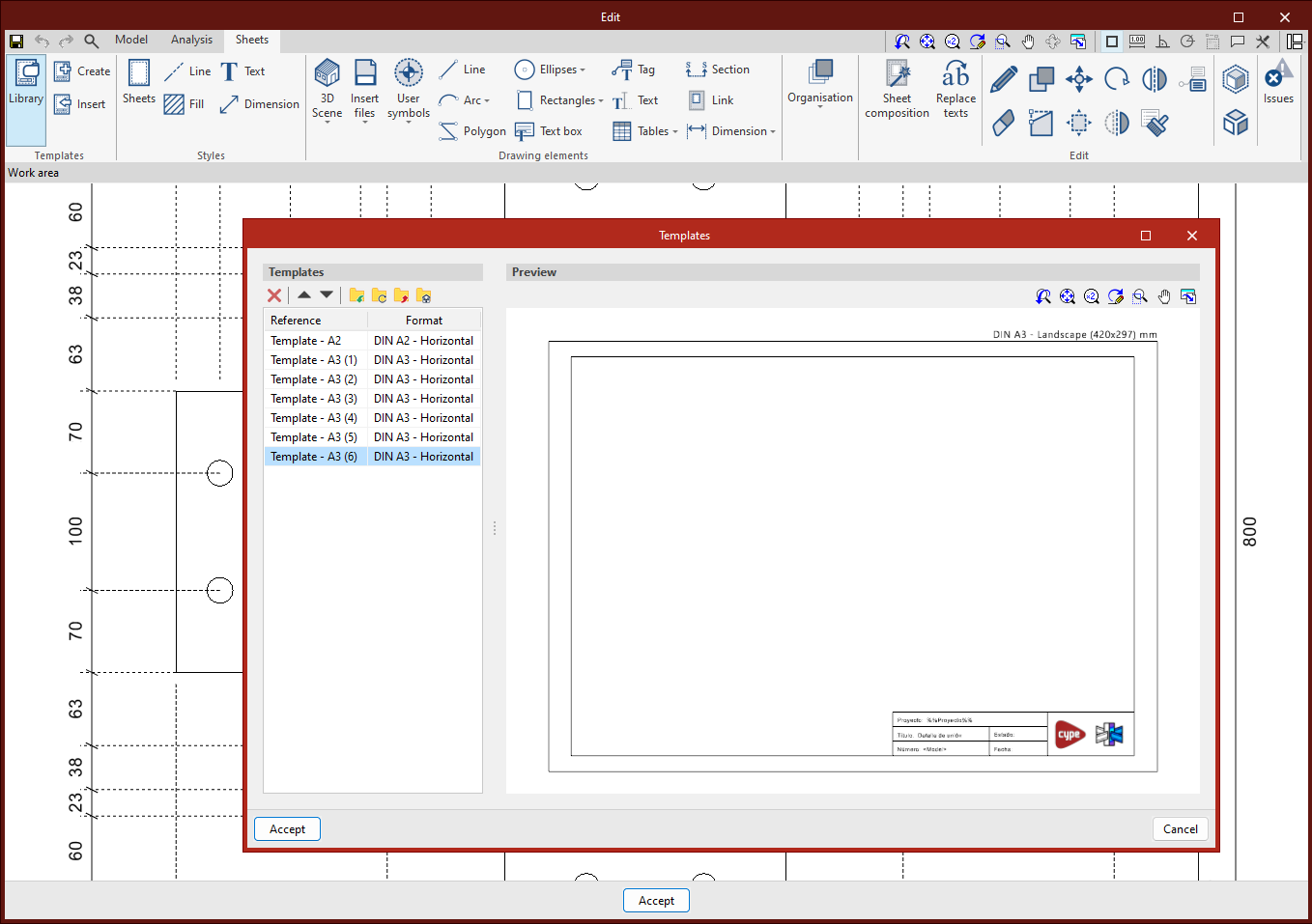
Insert templates
From the "Insert" option, the templates previously created and stored in the project are loaded.
There are different methods for loading a template:
- Load a template into a new sheet.
- Load the template into a previously created sheet.
- Load a template into another project.
Please note that the templates are normally designed for a certain paper size.
Template library
From the template library it is possible to view and manage the project templates. In this section the templates, created locally from the "Export the element to a file" option, are saved so that they can be used later in other projects.
With the "Import locally saved elements to the job" option, templates that have been saved locally are loaded.
Managing styles
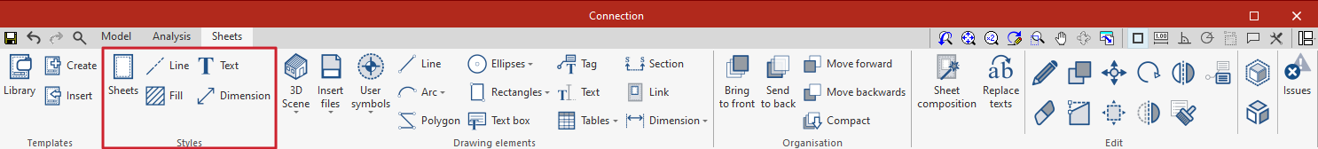
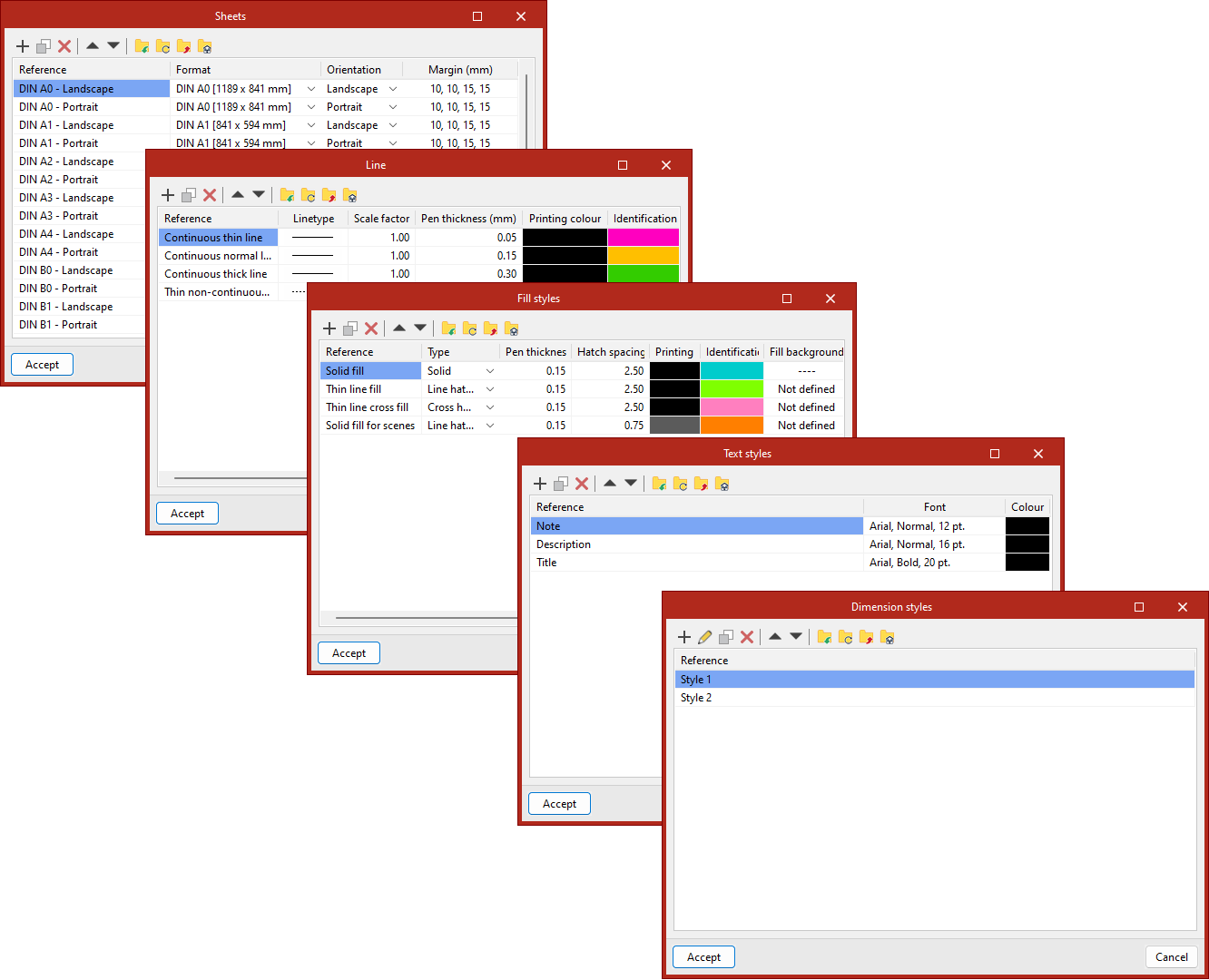
The "Styles" group offers the possibility to create customised libraries of sheets, lines, text, fills and dimensions. New styles can be generated from each pop-up window.
For "Sheets", the format, orientation and margins can be defined.
For "Lines", users can configure the stroke, the scale factor, the pen thickness, the colour for printing and the identifying colour.
For the "Text" style, the font, style, size and colour can be chosen.
Under "Fill", the type (solid, striped screen, inverted striped screen, etc.), the pen thickness, the screen spacing, the colour for printing, the identification colour and, if necessary, the background colour of the fill are selected.
The "Dimensions" section is divided into four sections: text, linear dimensions, areas and angles. In each of the tabs, the desired lines and symbols can be selected, as well as the thickness of the individual parts of the dimensions.
Styles can be exported for use in other projects, as well as imported from other projects. They can also be edited, duplicated, deleted and organised.
Drawing tools
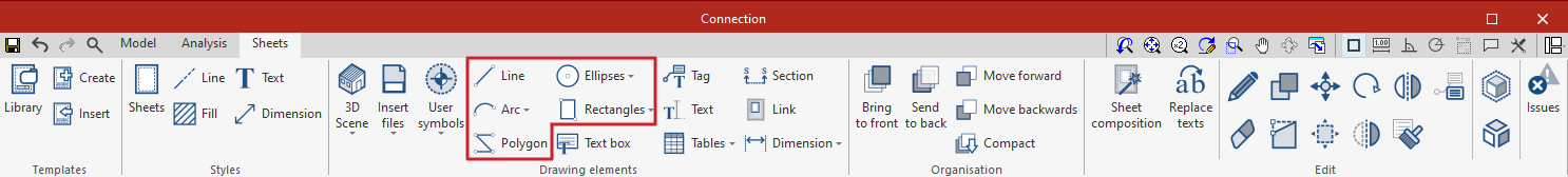
With the drawing tools for lines, arcs, polygons, ellipses and rectangles, these elements can be drawn in the sheet space.
Please note that the Ctrl key must be pressed to draw on the grid.
| Line | Consecutive segments can be drawn on the drawing as straight spans or arcs. It also offers the possibility to choose symbols at the ends. | 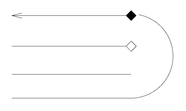 |
| Arc | It can be used to draw arcs given three points or given centre, start and end points. Symbols can also be entered for the start and end points of each arc. | 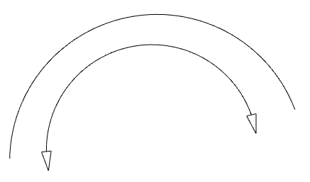 |
| Polygon | Polygons formed by rectilinear or curvilinear segments can be drawn. They can be filled. | 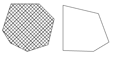 |
| Ellipses | Circles and ellipses can be represented. They can be filled. | 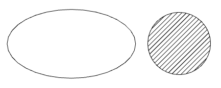 |
| Rectangles | Rectangles can be drawn with straight corners or with rounded corners. They can be filled. | 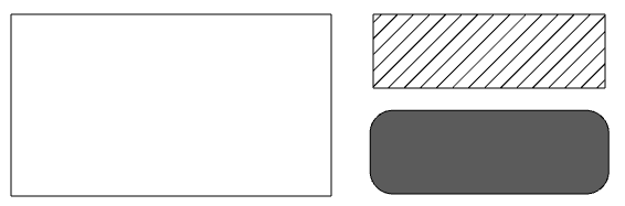 |
Entering and editing texts
Texto
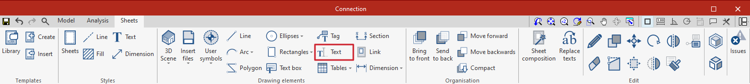
To insert text, first select the "Text" option in the "Drawing elements" group, which will open a pop-up window with the configuration options.
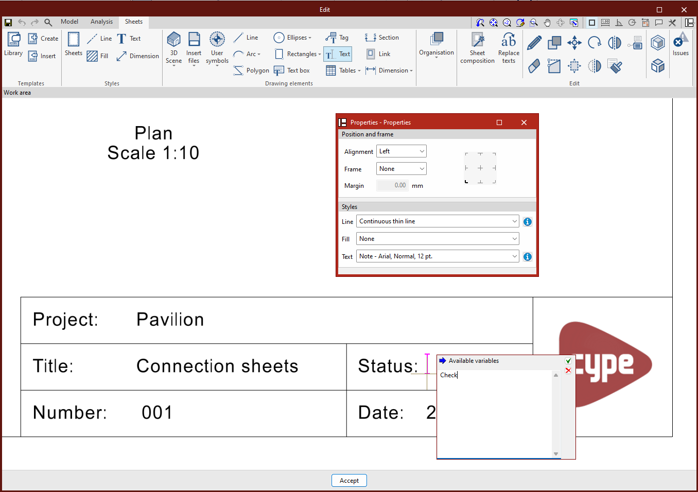
In this window, the positioning, frame and style of the text can be selected. Then place the cursor where you want to insert the text and press the left mouse button.
A new window opens, and the desired text is entered. Once the text has been entered, press the confirmation button to complete the process.
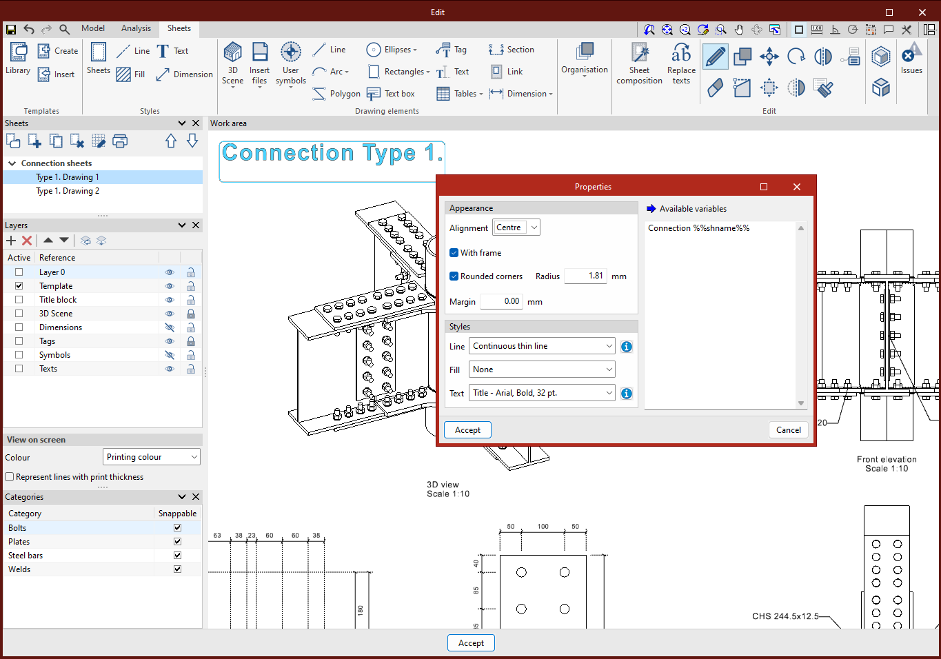
Text box
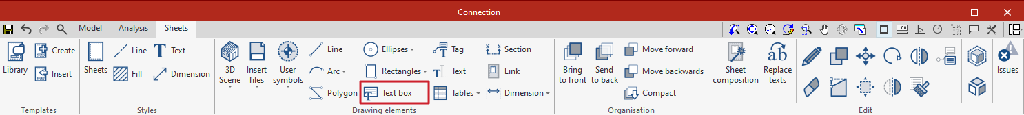
From "Text box" it is possible to enter a box containing the desired text.
The alignment, the choice of having a frame or not, and the type of corners preferred can be selected. The margins can also be adjusted according to your specific needs.
Furthermore, the box can be further customised by choosing line, fill and text formatting styles.
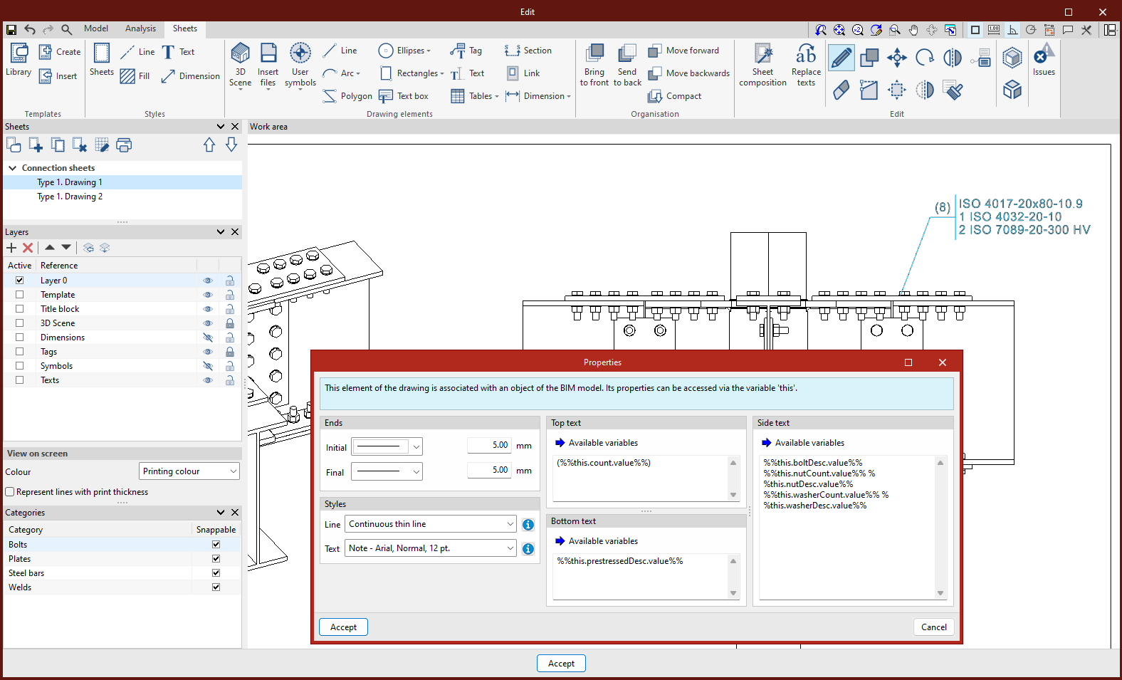
Replace texts
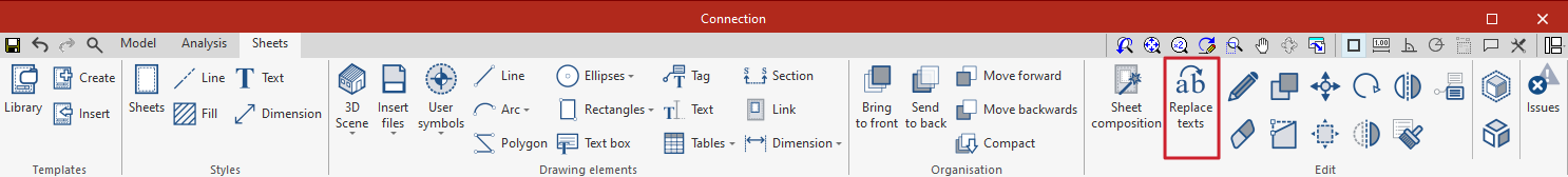
To add variable texts, go to the "Replace texts" icon. This option can be used to replace keywords with specific project data.
There are two types of text substitution variables: user variables and predefined variables.
User variables
User variables are used to create custom variables that can be reused in other sheets or projects. These variables can be the name of the project, the address, the responsible architect and engineer, etc.
User variables can be saved locally and loaded later into other projects via the "Import" button.
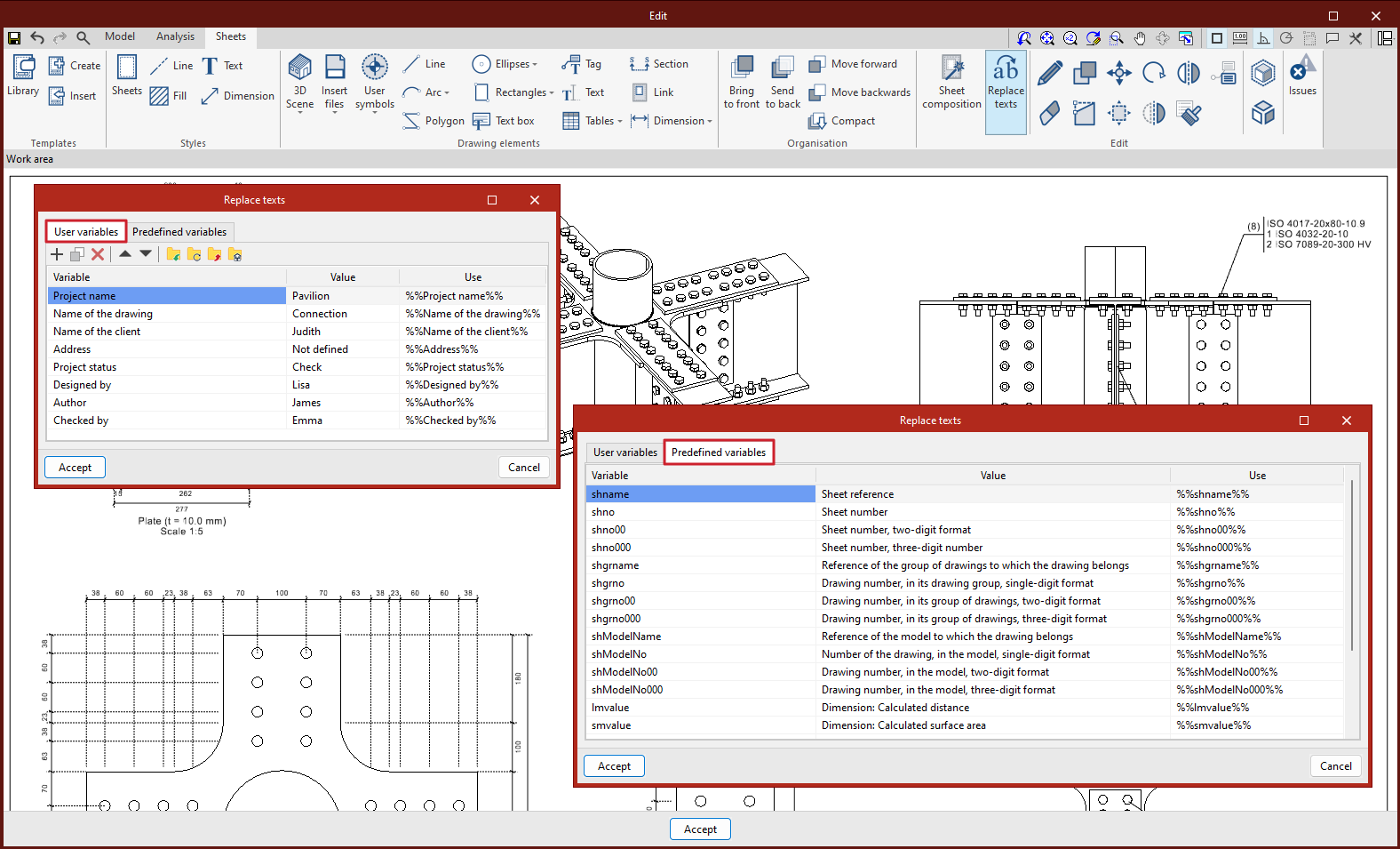
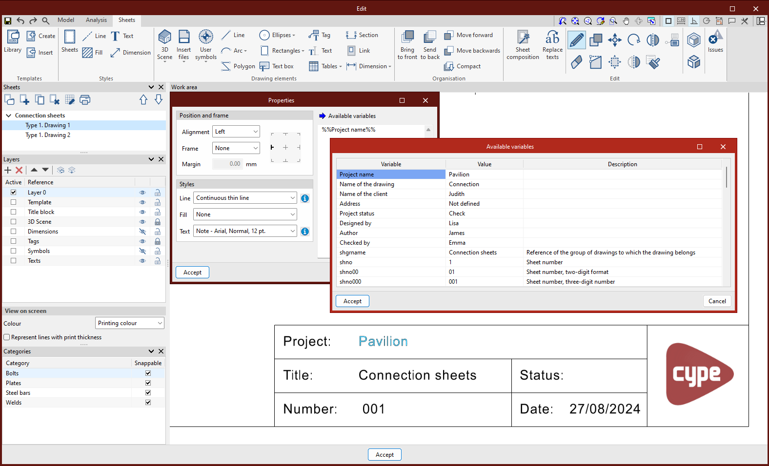
Predefined variables
Predefined variables can read data from the program and insert it as text into the sheets. These variables can be the sheet reference, sheet number, scale factor, etc.
Furthermore, predefined variables can also use information associated with tags, dimensions, scenes and views.
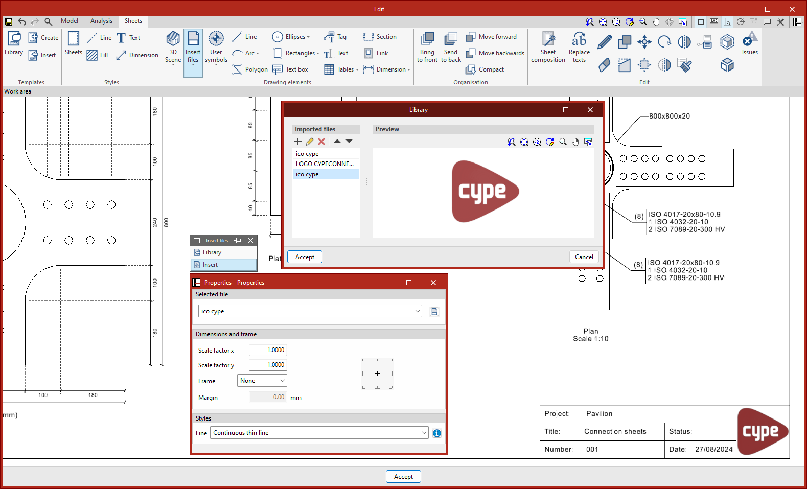
Entering external files
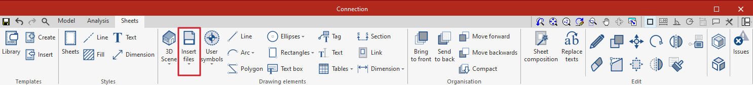
The program can insert external files, such as images and vector drawings, to complete the project information. The program imports DXF, DWG, DWF, JPEG, JPG, BMP, WMF, EMF and PCX formats.
The "Insert files" option is used to access the "Library" of external files, where files are imported into the program, and to "Insert", where the size and position of the element being inserted can be selected.
It is important to know that DXF and DWF formats also import layers. From the "Layers of inserted DXF or DWG files" option in the "Layers" section, the program allows you to modify the thickness and colour of the lines of the layers of these types of files.
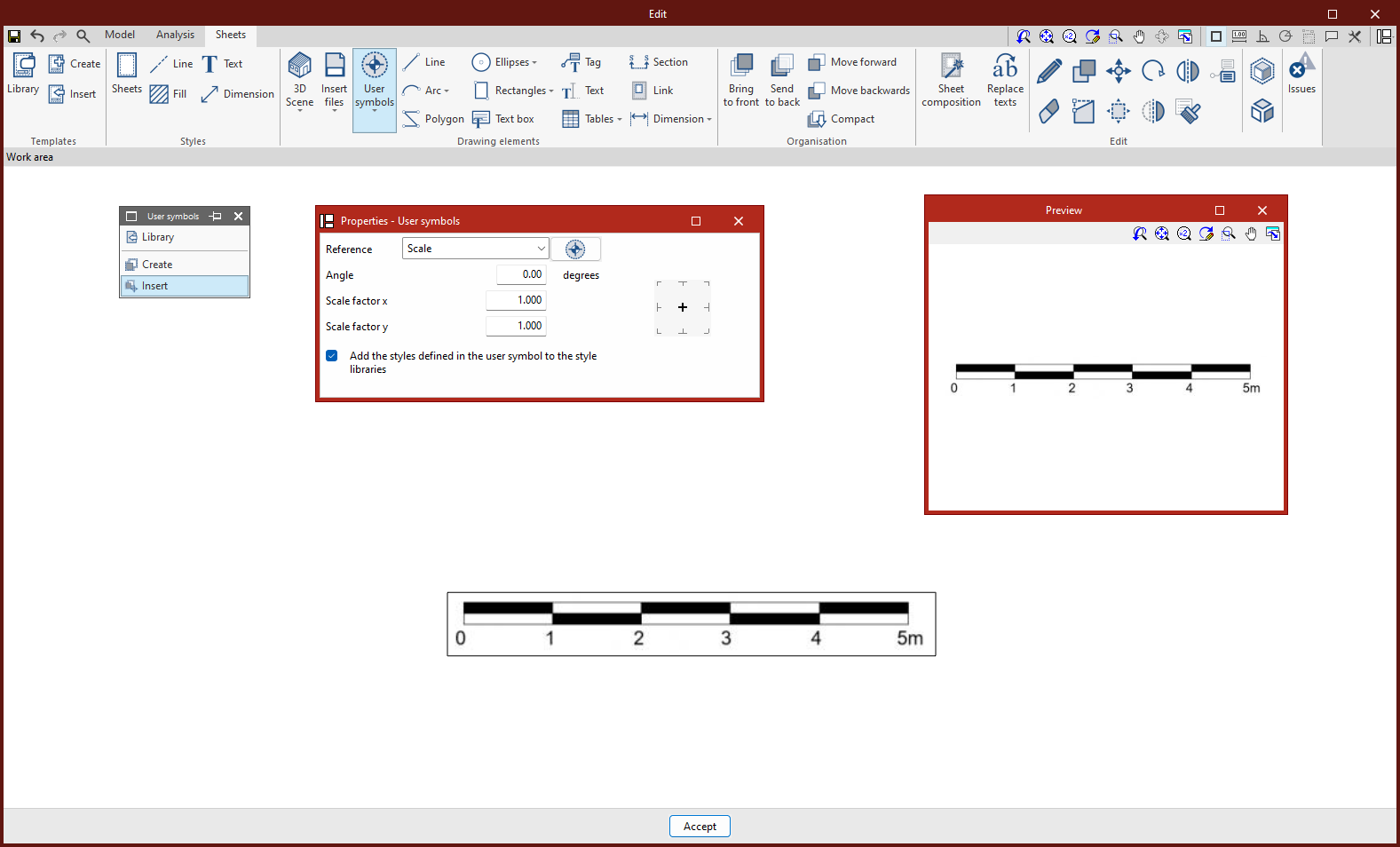
Creating and entering user symbols
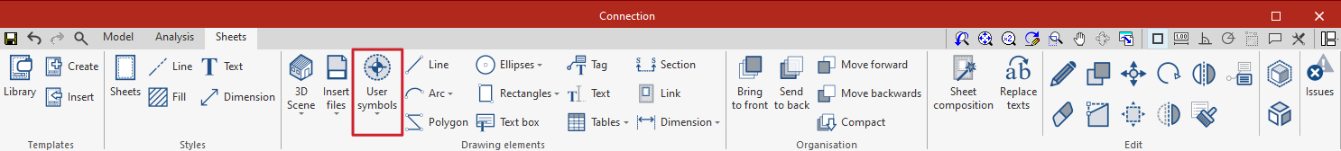
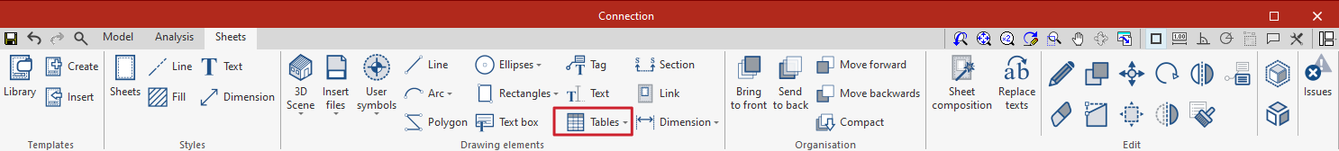
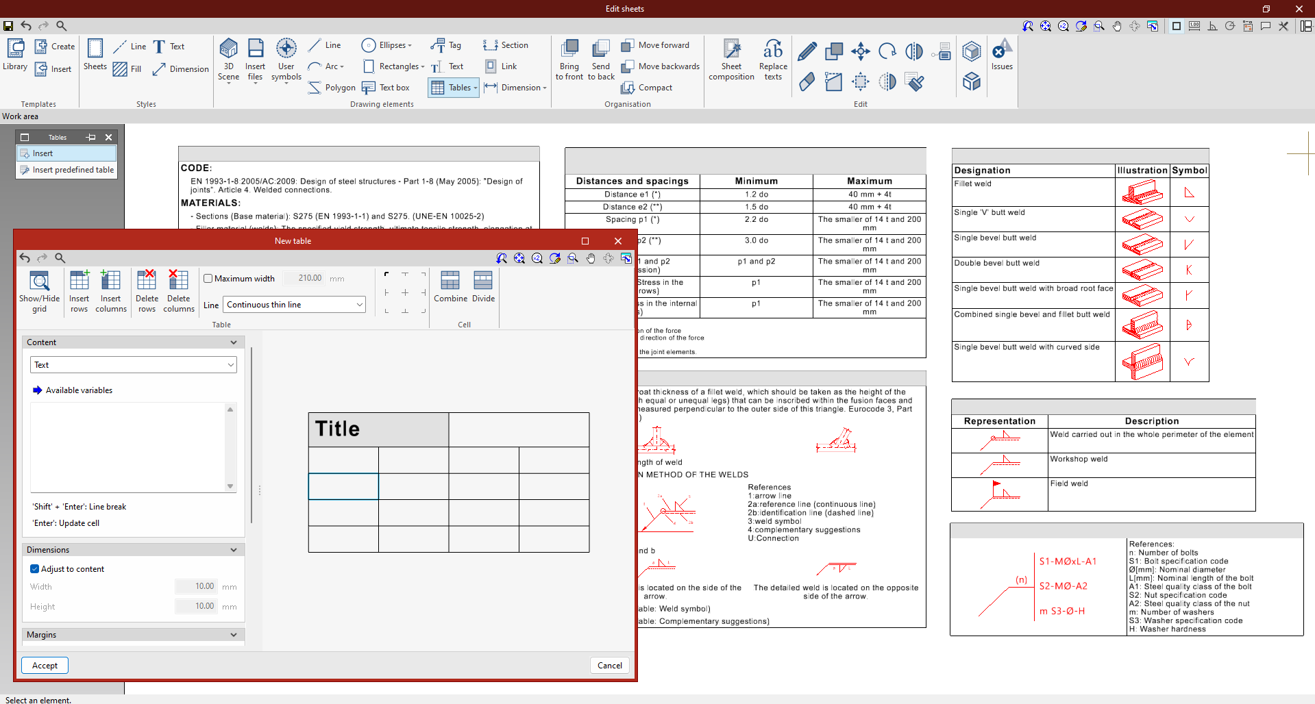
User symbols are created from the "Drawing elements" group. A user symbol can be created by means of lines, arcs, polygons, texts, tables, etc.
Under the "User symbols" button are the "Library", "Create" and "Insert" options.
User symbols can be saved locally and reused on other sheets or in other projects via the "Library" option.
3D Scenes: Entering BIM model views
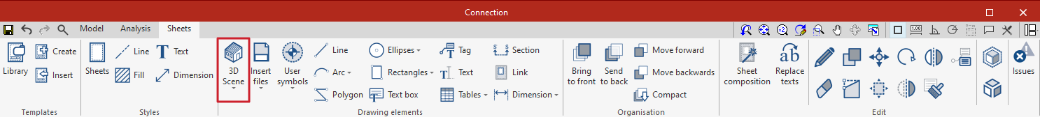
Once the sheet has been created, the next step is to enter the model to start elaborating on the plan views.
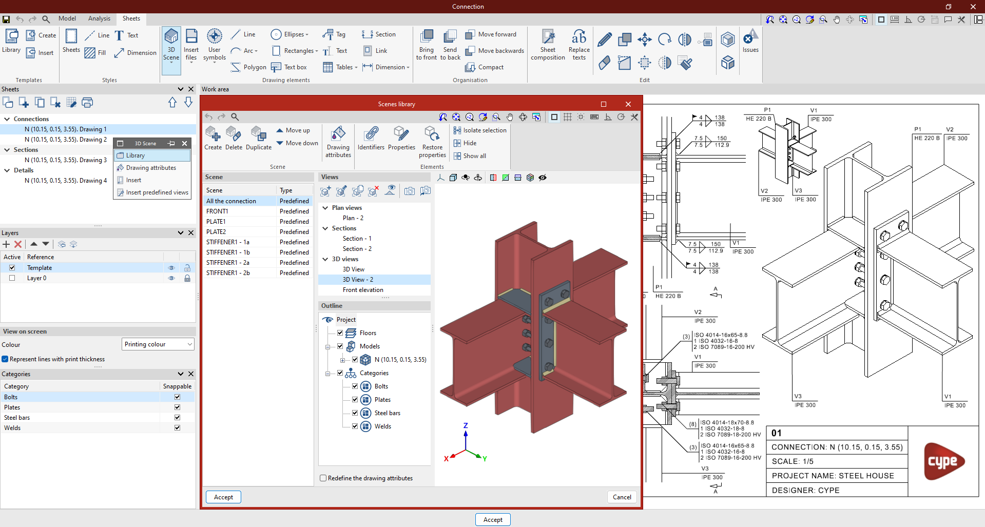
For this purpose, the 3D scene library is used, which facilitates the creation of scenes to be incorporated into the sheets.
Each scene can contain several views, and it is possible to select which elements are displayed in each of them via the "Diagram" section.
To insert a scene in the sheet, select the "Insert" button under "3D Scenes" and mark the box where the new scene is to be inserted.
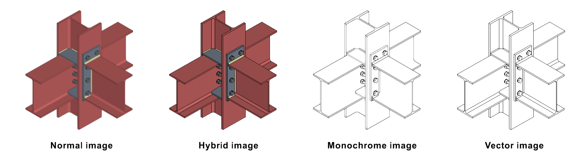
Once the frame has been inserted, the scene and the desired view can be selected, and the scale can be adjusted. In addition, different options can be chosen, such as drawing the scene in monochrome, normal, hybrid or vector. There is also the possibility of adjusting the display quality on the screen and the print quality.
Through this panel, it is possible to select another viewpoint and perform rotations, among other options.
Automatically generate connection drawings
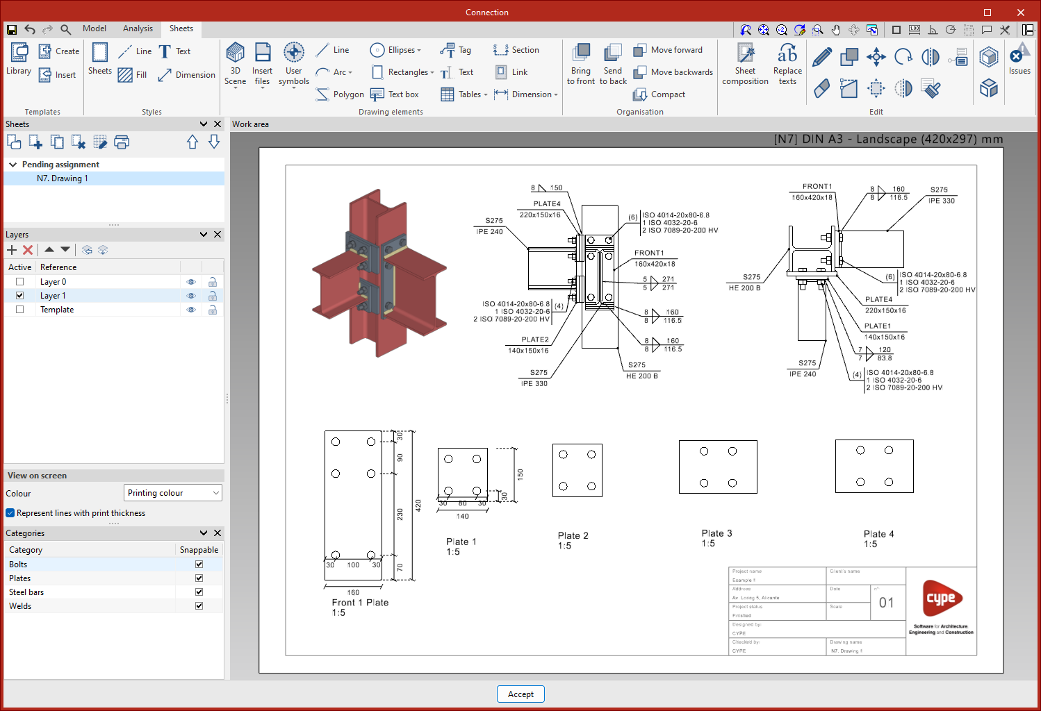
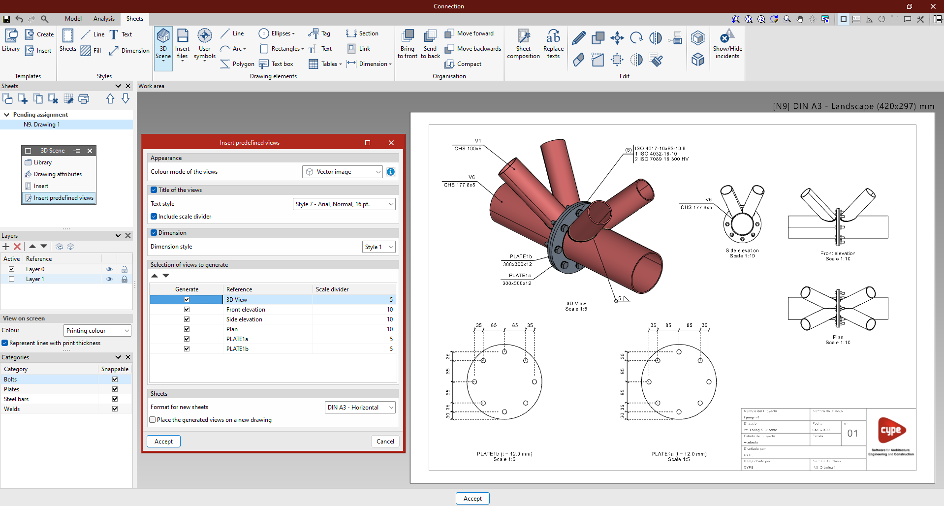
Inserting predefined views
Users can "Insert predefined views" in which the selected views can be configured.
In the pop-up panel, the selected view can be configured. The program can be used to choose the colour mode of the view, whether the view is to be dimensioned and referenced, as well as the respective styles, and to set the desired scale.
The sheet can be saved and the same process can be repeated with all the types of connections to be included in the final drawings.
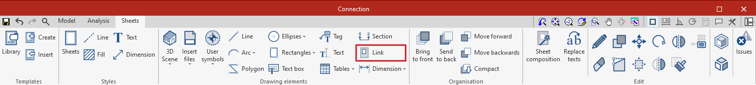
Linking to the connection model
The content of the sheets is linked to the connection model, i.e. the scenes and views that have been defined as well as the element tags that have been entered will be automatically updated if changes are made to the connection model. If the connection is exported to the "Connection library", the sheets will also be exported and can be reused in future projects.
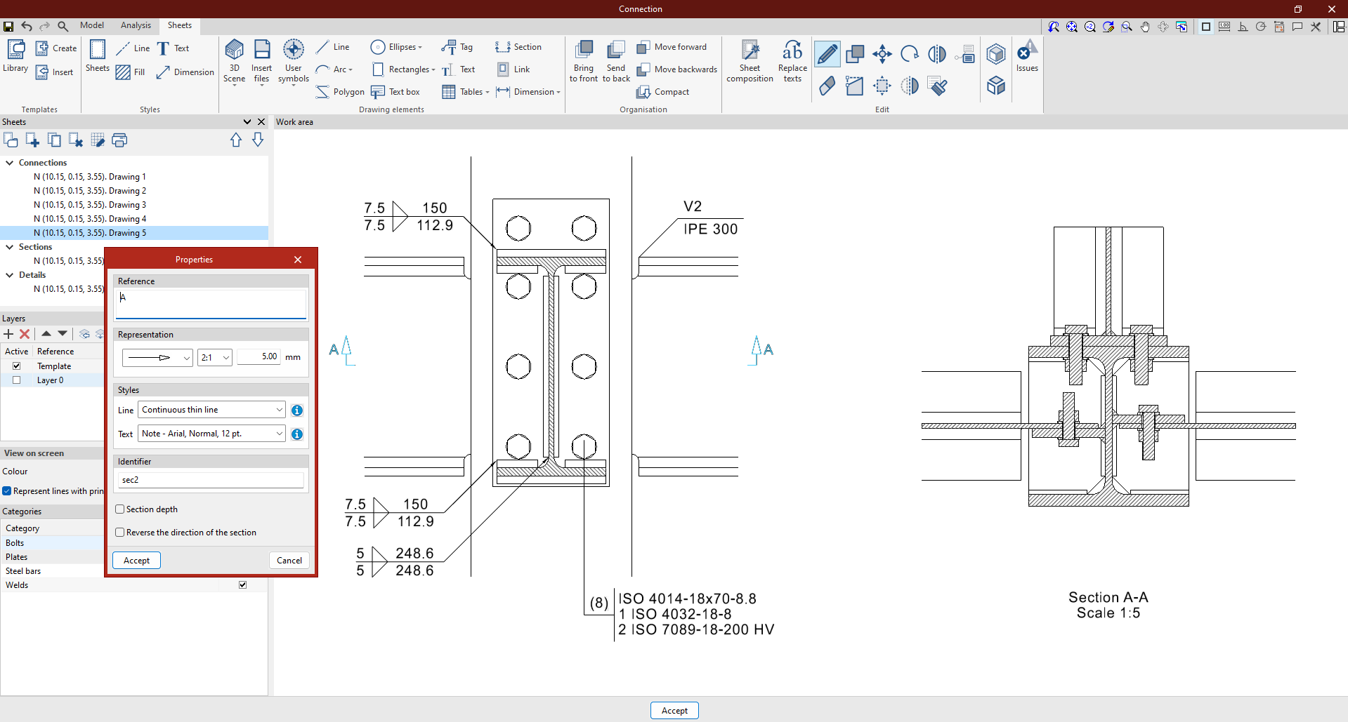
Creating sections from views

The "Section" tool can be used to easily generate sections from a 3D scene previously inserted into the drawing.
To do this, simply click on "Section" in the "Drawing elements" group and specify the numbering and style of the section to be created in the drop-down menu.
The precise location of the section on the already generated floor plan must then be specified. The corresponding section will be created automatically and can be edited according to the user's preferences.
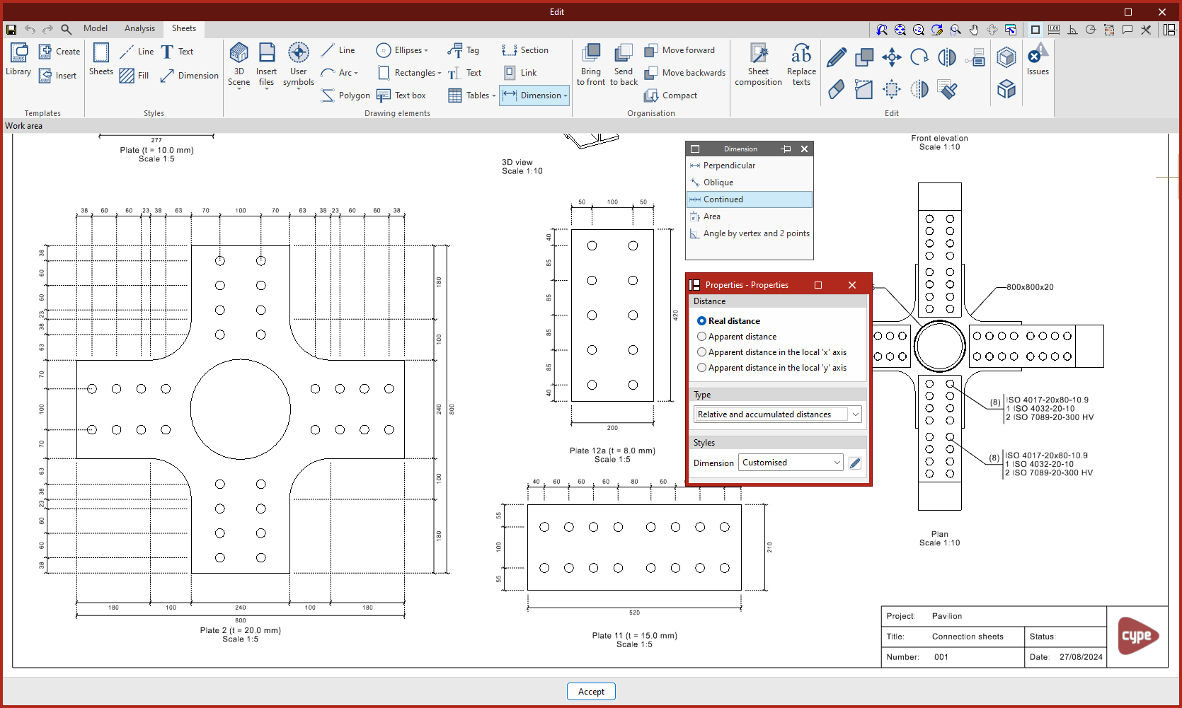
Dimension
The program can be used to dimension the scenes of a project in order to generate all the necessary information in the drawings. Four ways of dimensioning distances and angles are offered: "Real distance", "Apparent distance", "Apparent distance on local “x” axis" and "Apparent distance on local “y” axis".
Perpendicular and oblique dimensions
The main difference between the two is that the oblique dimension can choose the direction in which the dimension is to be drawn.
Continuous dimensions
The program offers three types of continuous dimensioning:
- Relative distance.
- Accumulated distance.
- Relative and accumulated distances: we recommend using this type of dimensions in elevations and sections to achieve a continuous dimensioning from a reference of "0.00".
Dimensioning area surfaces
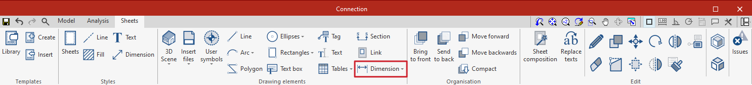
Within the "Dimension" button on the upper toolbar you will find the "Area" option.
With this feature, users can measure surfaces in the 3D scene and display their area as text.
Angle dimensioning
From the "Angle by vertex and 2 points" option, any angle of the drawing can be dimensioned.
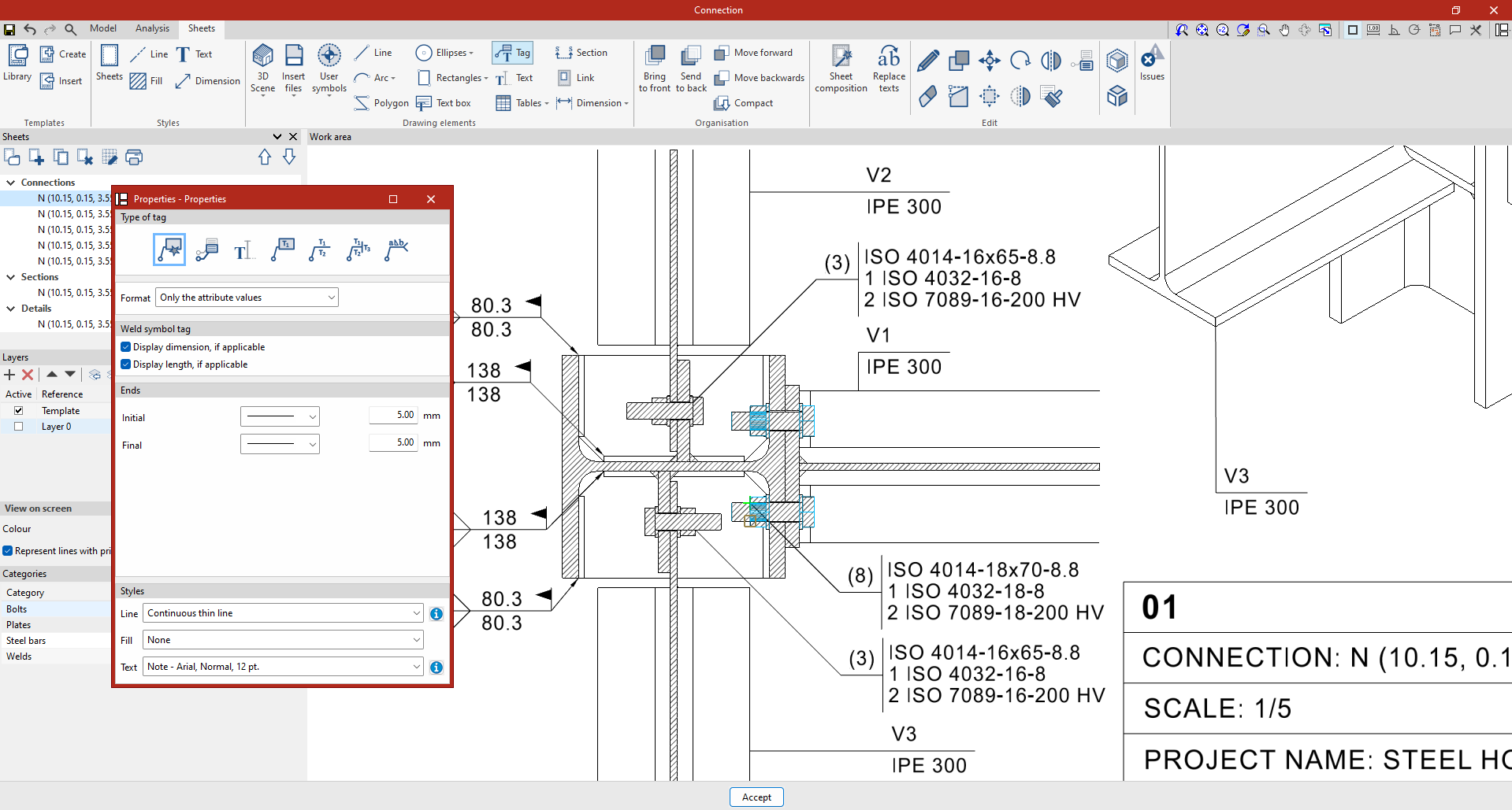
Tagging elements
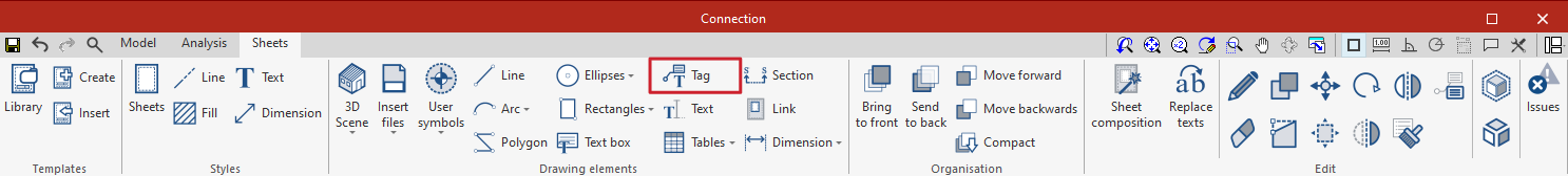
Tags can be used to extract information from the BIM model.
By clicking on a previously inserted 3D scene element, the tag will automatically detect the element and extract the data associated with it.
A tag can also be created without being associated with any element, and the text can be entered manually.

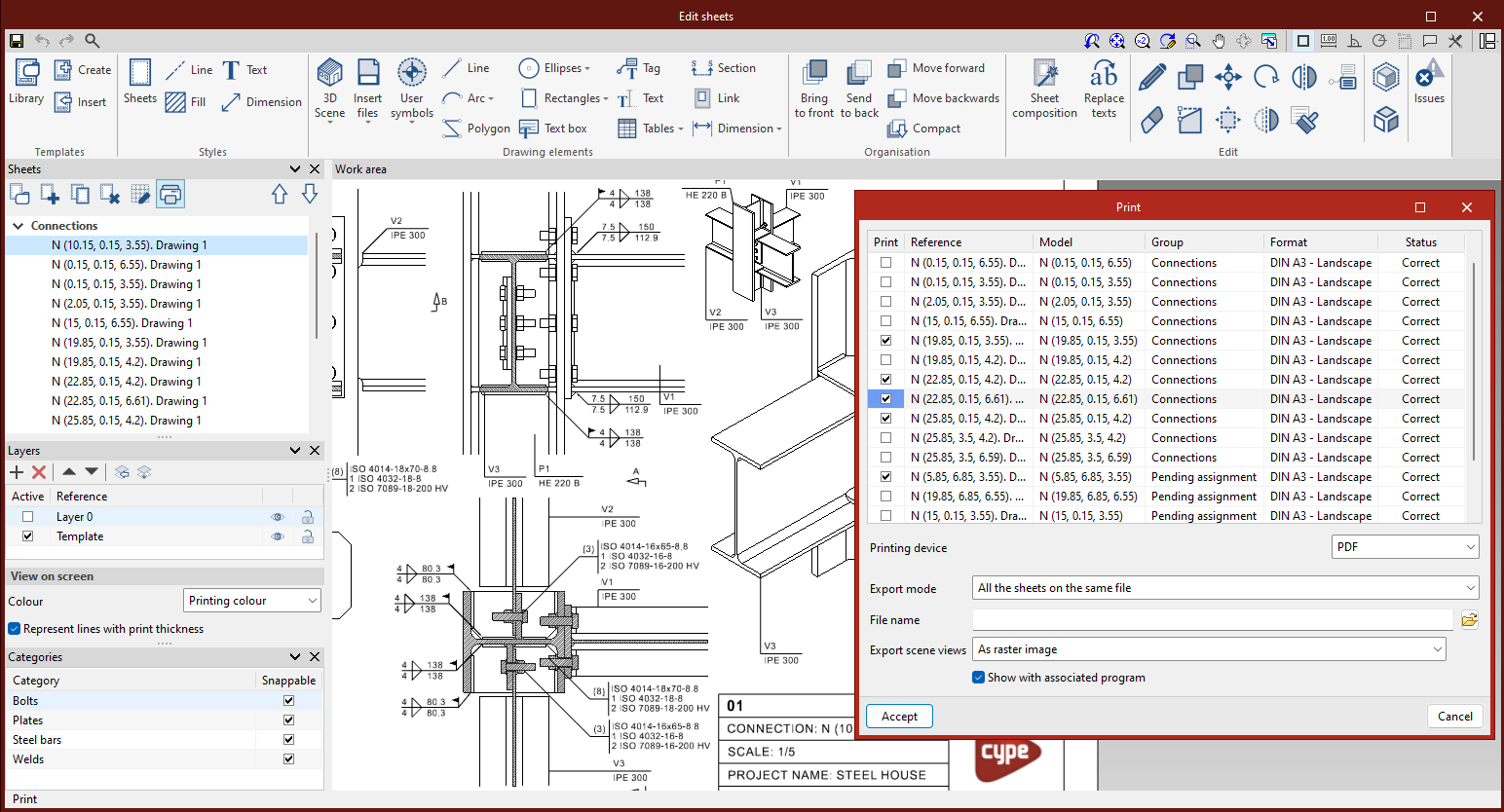
Results output
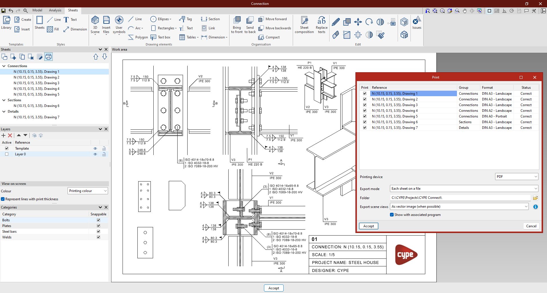
Once the project sheets have been assembled, they can be printed. To do this, click on the "Print" button and select the sheets and the desired format for printing the drawings. In the "Status" column, the program notifies if any of the elements entered are outside the printing area of the sheet.
The program can export the generated sheets in PDF, DWG and DXF format.
There is also a choice between exporting the films in one file, or each one in a separate file.
The program can also export scene views as a vector image or as a rendered image.
Managing drawings
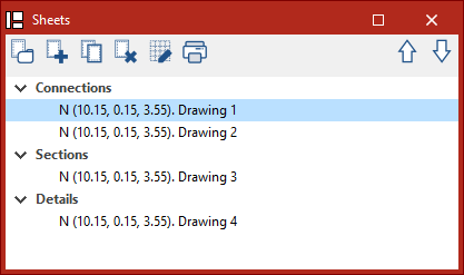
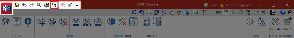
The following option is used to access the sheet editor, and even to manage all the sheets of all the previously generated connections individually. This is accessed from the "Drawings" option.
Clicking on this option opens a list with the sheets of all previously created connections.
New sheets can be created linked to the desired type of connection, or not linked to any connection and a sheet can be generated without an associated model.
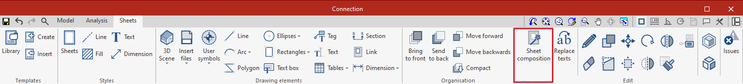
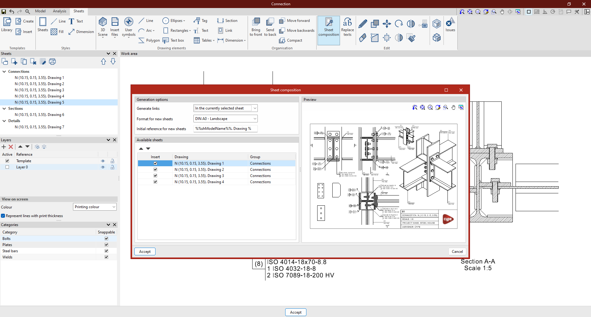
Alternatively, composite sheets can be created from other sheets using the "Sheet composition" feature. With this tool, all of the connection sheets that are to be inserted are specified. The program automatically distributes the views on the sheet. The "Move" option can be used to relocate the views.
From here, all the desired drawings can be printed from a single place without having to access each connection sheet individually.
To do this, click on the "Print" button to select all the sheets to be printed.
These sheets can be printed in different formats, such as PDF, DWG, or DXF, and each sheet can be exported to the same file or in a separate file.