

Dimension
The "Dimension" menu, within the "Drawing elements" section of the top toolbar in the sheet editor, offers options that allow you to dimension the scenes in a project in order to generate all the necessary information for the drawings.

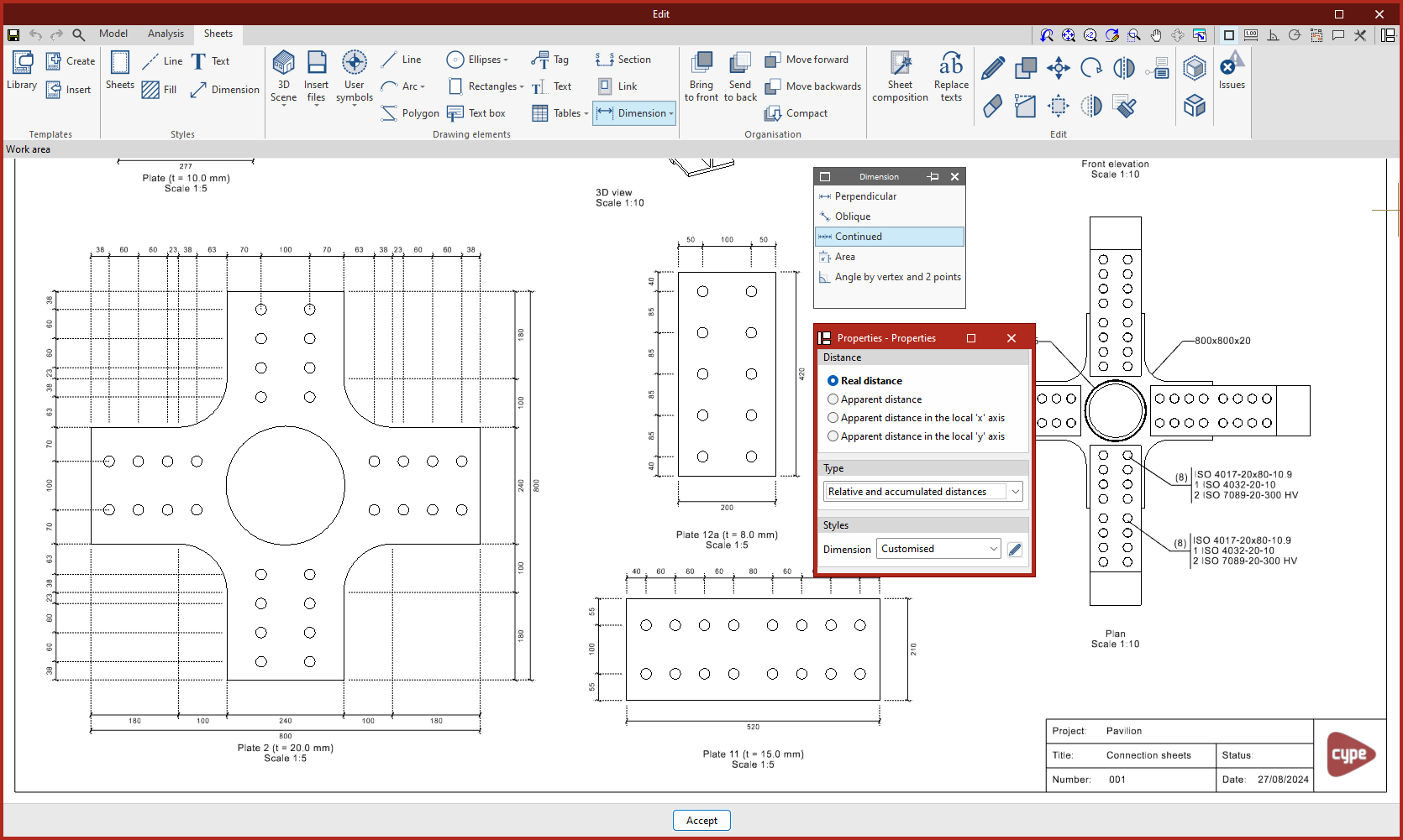
This menu displays the following options: "Perpendicular", "Oblique", "Continued", "Area" and "Angle by vertex and 2 points".
Perpendicular dimensions
The "Perpendicular" option allows you to enter perpendicular dimensions. To do this, select the two points that define the distance to be dimensioned and then position the dimension at the desired point in the workspace. The program will draw the dimension lines perpendicular to the dimensioned distance.
Oblique dimensions
The "Oblique" option allows you to enter oblique dimensions. To do this, after selecting the two points for the distance to be dimensioned, define the direction in which you want the dimension lines to be drawn (by selecting two more points in the work area); then, click on a point to position the dimension.
| Note: |
|---|
| When using the oblique dimensioning option, make sure you turn off the "Orthogonality" option, located in the top right-hand corner of the interface. |
Continued dimensions
The "Continued" option allows you to enter a series of continued dimensions by selecting several points.
The program offers three types of continued dimensions:
- Relative distance
The dimension shows only the distances between the marked points. - Accumulated distance
The contour line shows only the accumulated distance from the first point to the various marked points. - Relative and cumulative distances
The elevation mark shows both types of distance.
Relative distances are shown on the dimension line, whilst accumulated distances are indicated by text perpendicular to the dimension line.
Real and apparent distance
In the "Properties" window that appears when you use the "Perpendicular", "Oblique" or "Continued" options, the following methods of measuring distances are available:
- Real distance
The actual three-dimensional distance between the points marked on the model is measured. - Apparent distance
This is measured as the projection of the actual distance between the points onto the plane of vision. - Apparent distance in the local 'x' axis
This measures the projection of the actual distance between the points onto the view’s local 'x' axis. - Apparent distance in the local 'y' axis
This measures the projection of the actual distance between the points onto the view’s local 'y' axis.
| Example: |
|---|
| The real distance is the projection of the actual distance onto the plane of a given view. For example, in a plan view showing a sloping element with an actual length of 2 m and a gradient of 30 per cent, the real distance is 2 m, and the apparent distance (measured on the horizontal plane) is 1.92 m. |
In addition, the "Styles" dimension must be selected.
Surface area dimensioning
The "Area" option is located within the "Dimension" option on the top toolbar.
This feature allows you to measure surfaces in the 3D scene and display their area as text.
In the "Properties" window that appears when you select this option:
- Specify whether the "Plane to calculate the area" is:
- The "Global XY plane in the z-coordinate of the first point"
- The "Plane defined by all the points"
- Select whether each "Segment" is a "Line", an "Arc defined by 3 points", or an "Arc defined by start, centre and end"
- Select the dimension "Styles"
Angle dimensioning
Using the "Angle via vertex and 2 points" option, you can constrain any angle on the plane.
In the "Properties" window that appears when you select this option:
- Specify whether the "Angle" to be measured is:
- The "True angle" between the elements of the model
- The "Apparent angle" in the projection of the view
- Select the dimension "Styles"
