
Drawings of coupling beams
StruBIM Shear Walls includes tools that allow for the automatic or manual generation of drawings for the coupling beams designed within the program. These drawings include elevations and cross-sections of the beams, which facilitate the graphical documentation of the designs produced.
The types of drawings generated are:
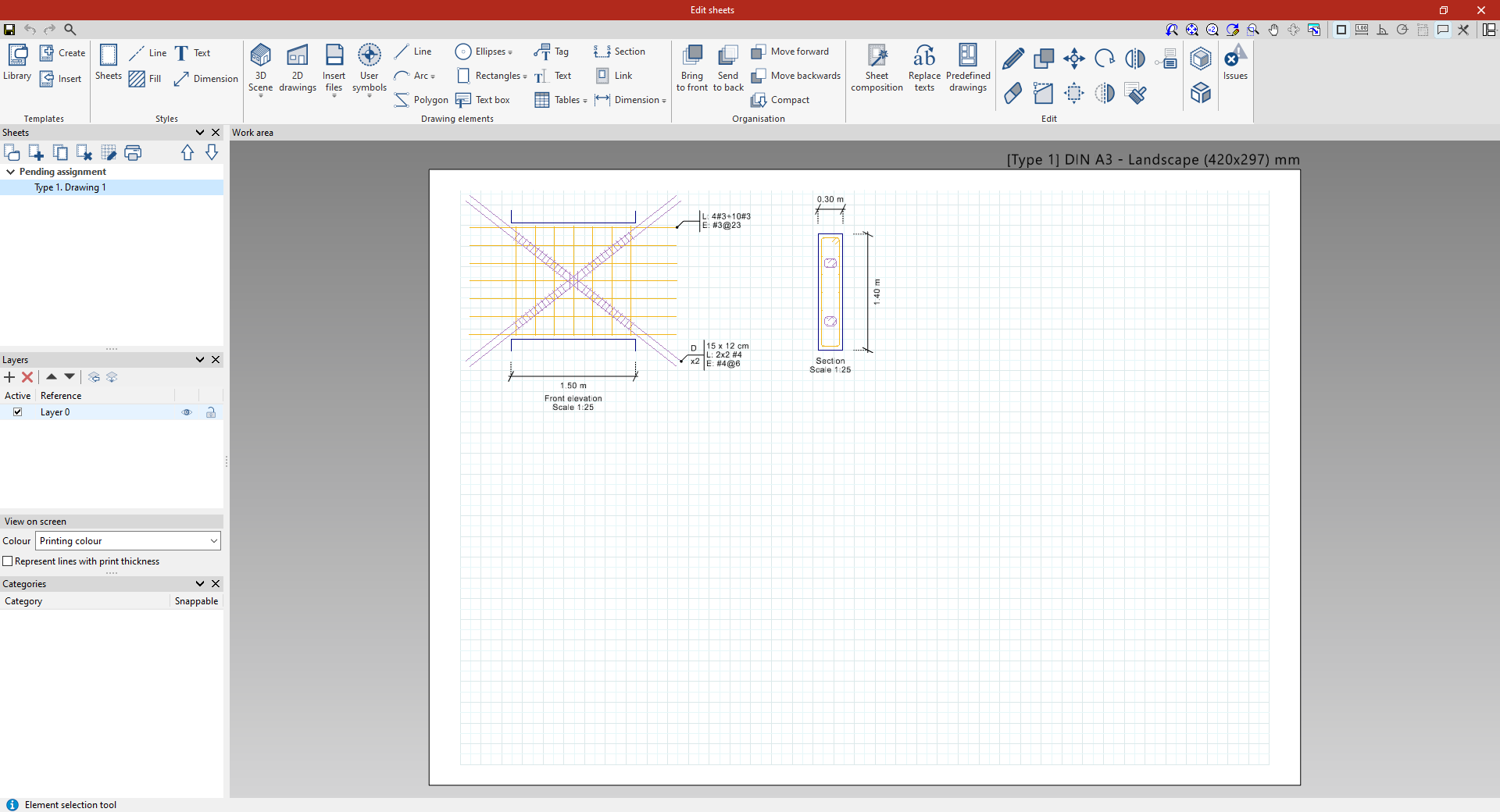
- Elevation
View of the connecting beams. - Section
View of the section of the coupling beam.
The perimeter reinforcement of the beam and the diagonal stiffeners are marked.
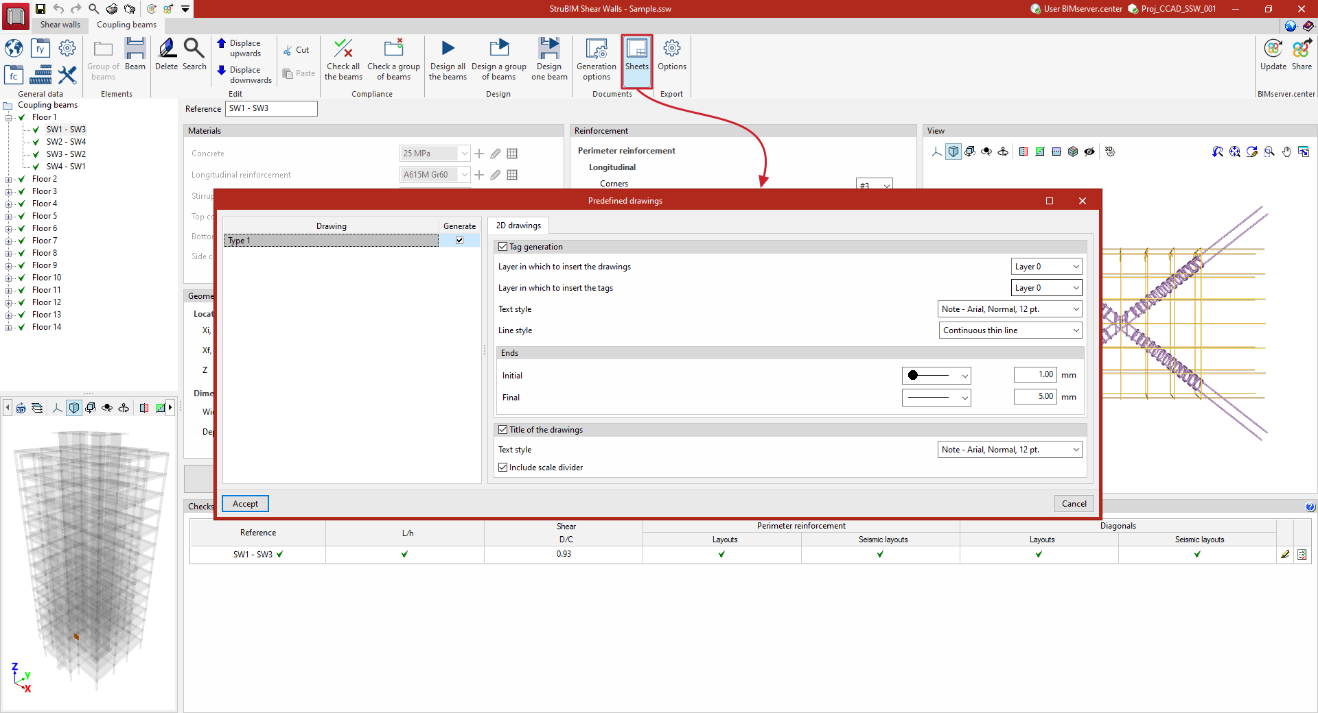
Access to the slide editor
Clicking on the "Sections" icon within the "Documentation" section opens the section editor for the selected beam.
The first time you access this section, the program will ask if you wish to automatically generate the predefined sheet layout. The layout of each sheet will depend on the settings previously selected under "Generation options".
You can rearrange the content using the "Move" option in the "Edit" panel, and insert other drawings from "2D Drawings" in the same panel.
Setting the display of sheets
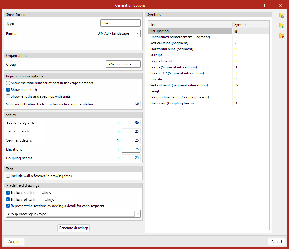
In the "Generation options" dialogue box, which includes tools for generating both beam-to-beam connection plates and shear walls, you can define:
- Slide format
Defines the format of the sheets generated:- Using the "Type" option, you can select a template so that the sheet adopts the format associated with it.
- The "Clear" option allows you to manually set the sheet format.
- Organisation
Specifies the slide group into which the generated slides will be inserted. - Display options
This section contains the following options:- Show the total number of bars in the edge elements
When enabled, the reinforcement labels for edge elements show the total number of vertical bars (e.g. 14 #10). If disabled, the number of layers and the number of bars per layer are shown (e.g. 2x7 #7). - Show bar lengths
Adds the bar lengths to the labels on the horizontal bars. - Show lengths and spacings with units
- Scale amplification factor for bar section representation
- Show the total number of bars in the edge elements
- Scales
- Scale divider for drawing:
- Section diagrams
- Section details
- Segment details
- Elevations
- Coupling beams
- Tags
- Include the wall reference in the title of the drawings.
- Include the wall reference in the title of the drawings.
- Predefined drawings
- Specify whether the predefined wall sheets should:
- Include section drawings
- Include elevation drawings
- Represent the sections by adding a detail for each segment
Choice between two display modes. If this option is disabled, the entire section is shown with all its reinforcements. If enabled, a general outline of the section is displayed along with specific details for each segment. - Drawings can be displayed as one per sheet or grouped by type.
- Symbols
Defines the symbols or abbreviations used in the text, notes and explanations that appear on the labels.
Generating predefined sheets
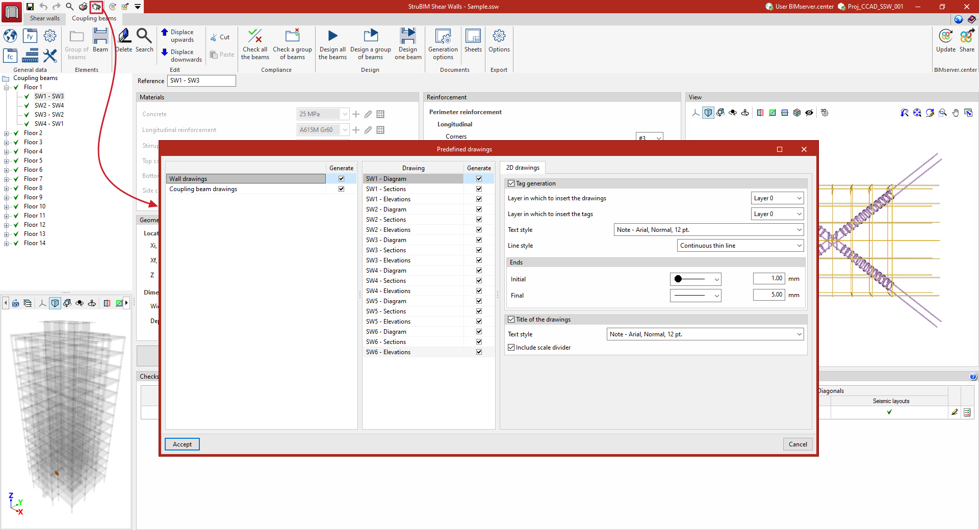
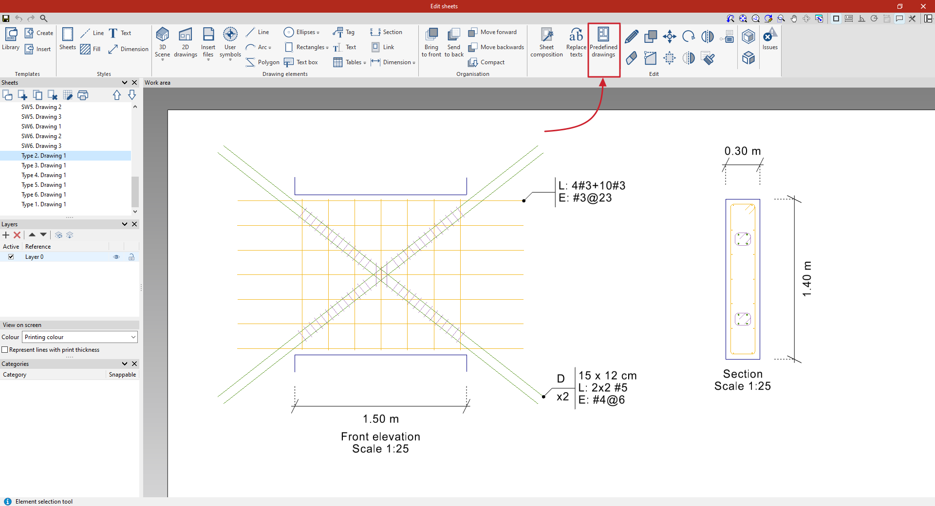
The sheets for each element can be generated automatically either when you first access the "Slides" section or, within that section, via the "Predefined slides" option.
It is also possible to generate drawings of all shear walls and all connecting beams in the project using the "Drawings" option in the "File" menu or at the top of the main interface.
When these options are used, depending on the settings specified under "Generation options", the program generates the section and elevation drawings, together with the reinforcement labels.
The elevation drawings show the length of the beam and depict and label the longitudinal reinforcement and diagonal bracing, including corner bracing, additional bracing on the faces of the beams, the stirrups for the longitudinal reinforcement, and the bars forming the diagonal bracing and their stirrups.
The sections show the depth and width of the beam, and illustrate the longitudinal reinforcement and its stirrups, as well as the reinforcement for the two diagonal braces.
| Further information: |
|---|
| The user interface of the sheet editor is similar to the one in CYPE Connect; detailed information on this is available via the following link. This sheet editor is also integrated into other programs, such as StruBIM Steel and CYPE Architecture. |
