
Data input and output sequence (sheet editor)
Graphical documentation of the structure or parts of it can be carried out in the sheet editor using the following basic sequence of data input and output:
- Access the sheet editor (options in the "Documents" tab or the "Sheets" tab of the joint editor).
- Review sheet formats and other styles (the "Styles" panel), as well as the available variables ("Replace texts").
- Create sheets (the "Sheets" panel on the left-hand side).
- Create layers (the "Layers" panel on the left-hand side).
- Insert the template ("Templates" group, "Insert"). If no template is available, you must first draw one by entering its constituent elements (using the options in the "Drawing elements" group) and then create the template ("Templates" group, "Create").
- Insert model views (the "3D Scenes" menu):
- Prepare 3D scenes ("3D Scenes" menu, "Library").
- Insert 3D scenes (the "3D Scenes" menu, "Insert").
- Insert graphic elements (the "Drawing elements" group):
- Add tags and dimensions to the elements depicted in the scenes.
- Insert other graphic elements to complete each sheet: lines, text, tables, etc.
- Insert sections and links to other sheets (optional).
- Print sheets (the "Print" option in the "Sheets" panel).
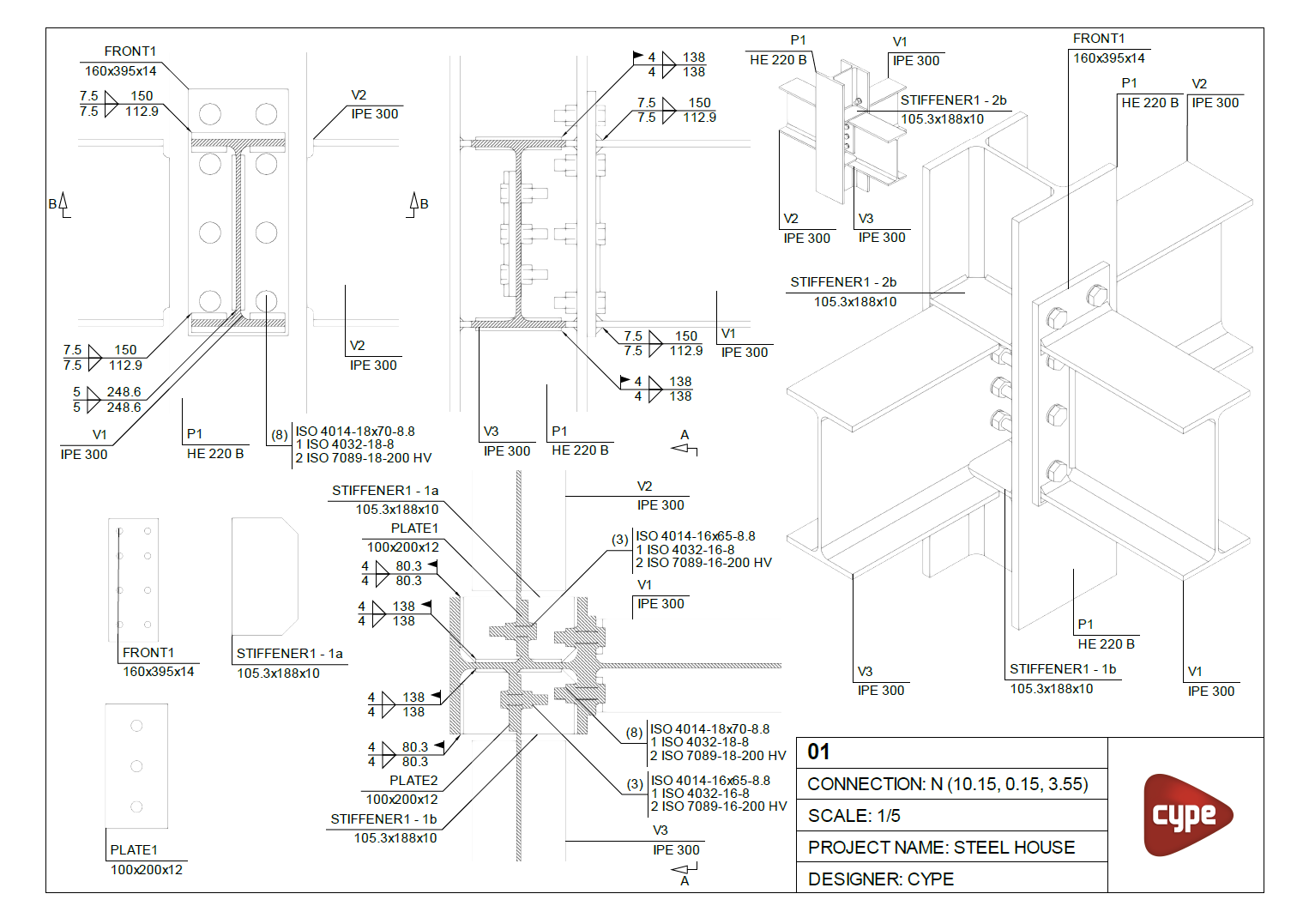
Accessing the sheet editor
The sheet editor is a dedicated interface that lets you work on and print the graphical documents for the various components of the structure developed in the program, and it can be accessed in several ways:
- From the "Sheets" tab in the joint editor
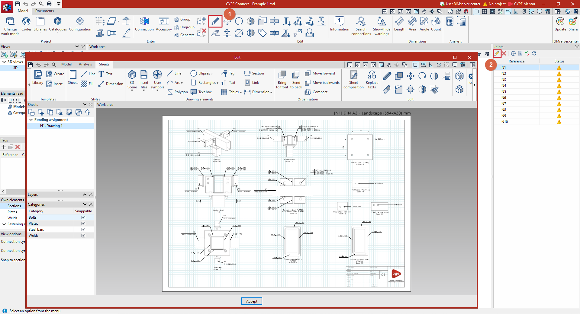
You can arrange the sheets for the connection you are currently editing. To access the connection editor, you can:- Use the "Edit" option (1) in the main interface, within the "Edit" section in the top toolbar on the "Model" tab, on a visible connection in the work area.
- "Edit" (2) a joint from the joint management panel, located on the right-hand side.
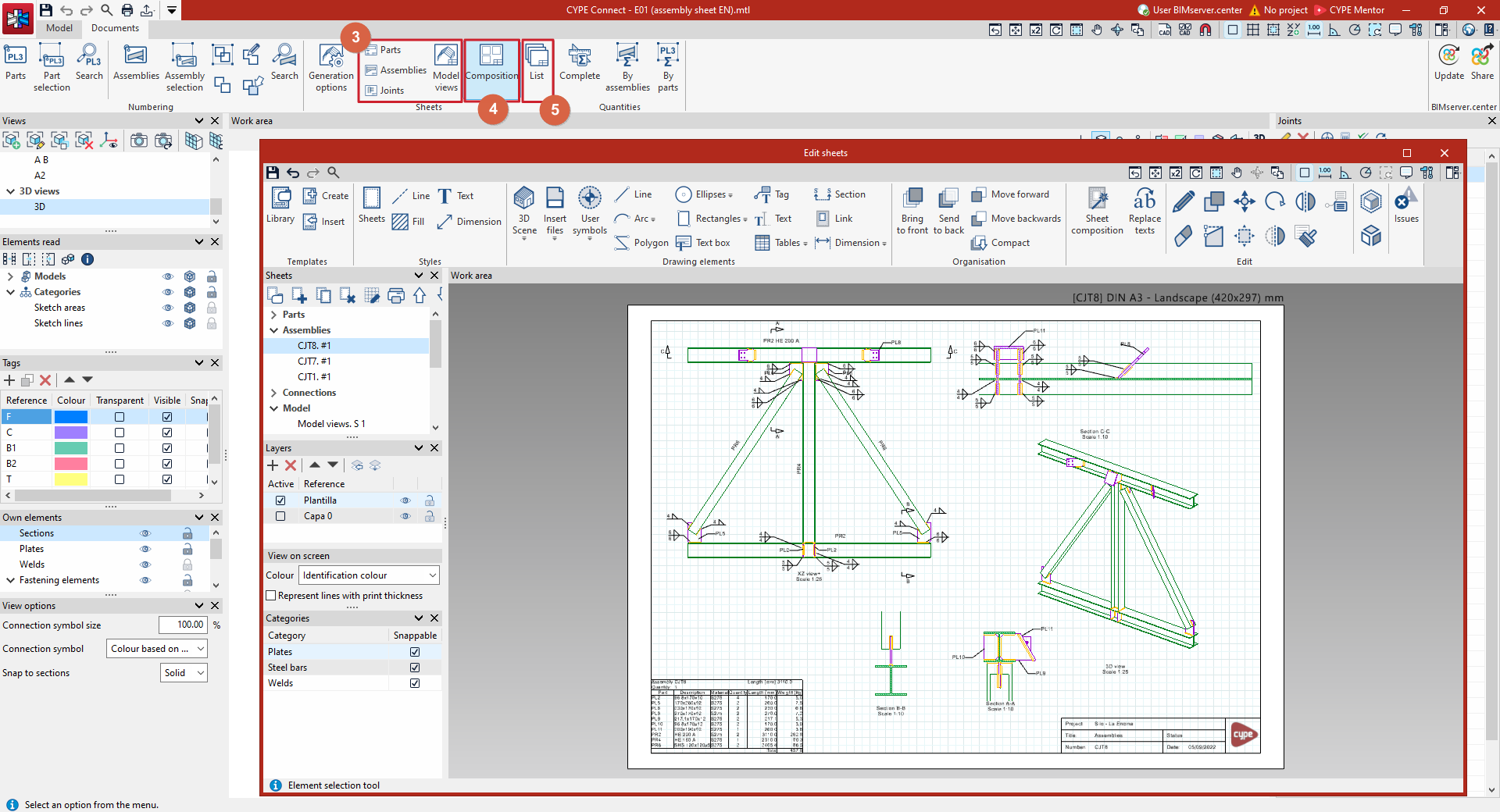
- From the options in the "Sheets" section of the "Documents" tab in the main interface
These let you edit all the sheets that can be created in the program:- The "Parts", "Assemblies", "Joints" or "Model views" options (3) allow you to access, respectively, the sheets for each part and each assembly (in "Fabrication" mode), the sheets for each joint, and the model view sheets.
- The "Composition" option (4) allows you to view all the sheets created in the project and includes the option to create a sheet composed of other sheets.
- The "List" option (5) provides access to each of the previously created drawings of parts, assemblies, joints and model views.
The sheet editor’s work environment
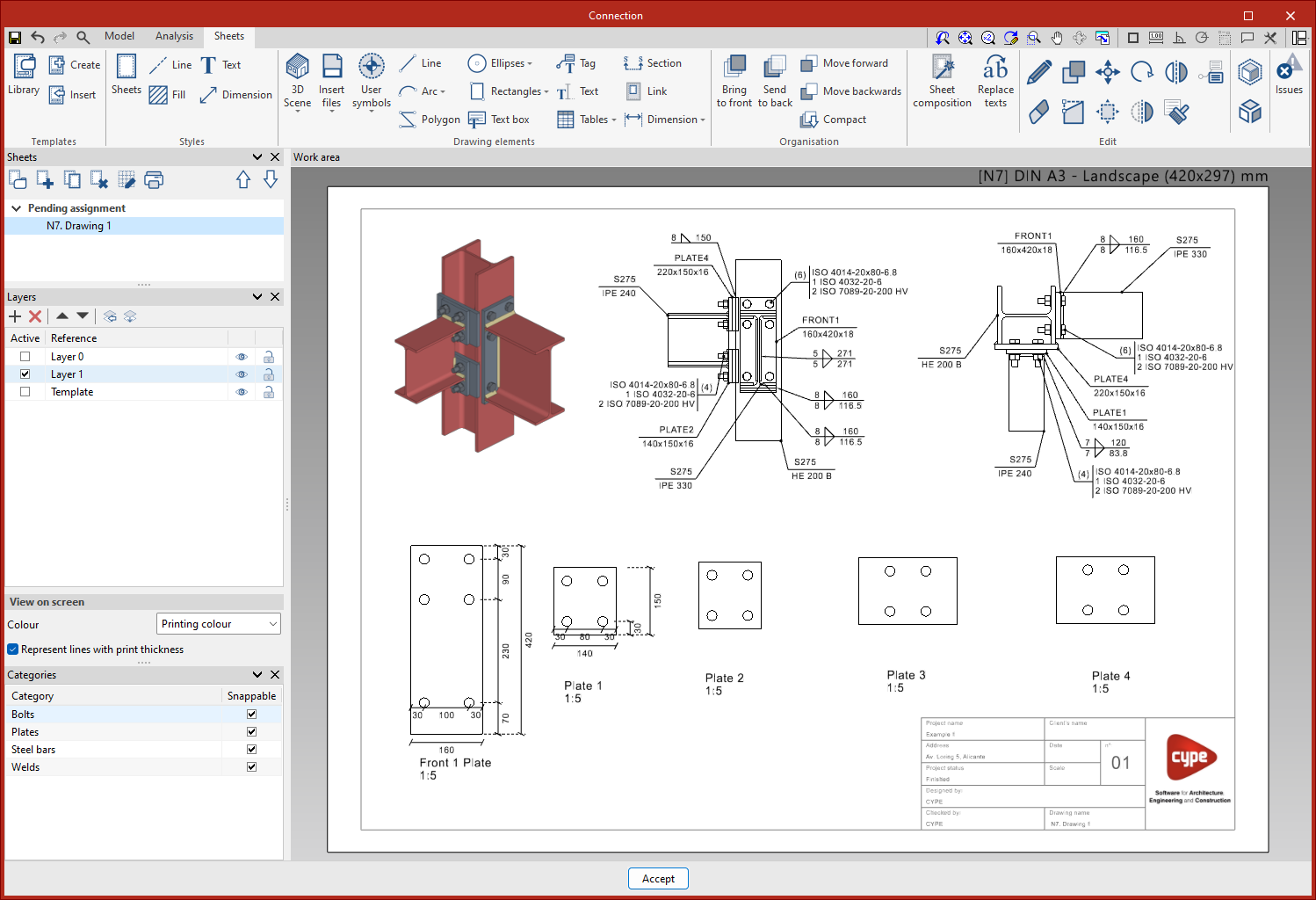
The user interface of the "Edit sheets" window is similar to that of other CYPE modelling tools and features a system of dockable windows that can be customised to adapt the workspace to the project’s requirements.
The interface is divided into three main parts: the top toolbar, the sidebar and the workspace.
- The toolbar contains various features. From here, you can create and manage templates, edit styles, and insert, edit or reorder drawing elements, as well as other options.
- The work area is located on the right-hand side of the screen and lets you view the layout of each sheet.
- On the left-hand side are the main tools for managing the project’s sheets, layers and categories. Furthermore, in the "On-screen display" section, you can select how you wish to display the thickness and colour of the elements.
Managing and creating sheets
"Sheets" panel
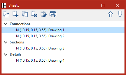
The "Sheets" panel on the left-hand side of the "Edit sheets" window displays a list of the sheets for the structure or the relevant structural component, organised into drop-down groups.
At the top of the list, the program offers various options to make it easier to manage sheets, amongst other things. The available options are as follows:
- Sheet groups
This opens a window where you can create or delete groups of sheets. Sheet groups allow you to organise the sheets in the list. - New sheet
Create a new sheet. - Duplicate sheet
Create a new sheet by copying the existing sheet that is currently selected. During this process, the program allows you to specify the "Reference" for the duplicated sheet, assign the duplicated sheet to a new "Group" of sheets and/or select a different "Format" for it. - Delete sheet
Delete the currently selected sheet. - Grid
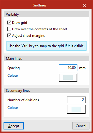
The grid is a set of lines that can be displayed on the sheet and can serve as a reference to make it easier to place graphic components on the sheet (using the "Ctrl" key to snap to the grid if it is visible). Using this option, you can adjust the visibility of the grid and its lines:- Visibility
Control the visibility of the grid. You can:- Draw the grid (optional)
- Draw over the contents of the sheet (optional)
- Adjust sheet margins (optional)
- Main lines / Secondary lines
Adjust the "Spacing" and "Colour" of the main grid lines. - Secondary lines
Select the "Number of divisions" and the "Colour" of the secondary lines in the grid.
- Visibility
- Print
Print the drawings, generating PDF, DWF or DXF versions of the drawings you have created.
Creating new sheets
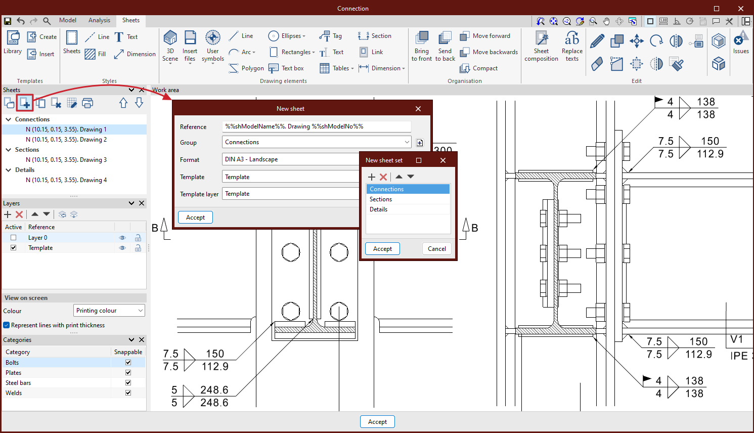
To get started, the first thing you need to do is create a new sheet.
To do this, after clicking on "New sheet", enter the following details in the pop-up window:
- The "Reference" or name of the sheet under which it will appear in the list (which allows the use of variables managed via the "Text substitution" option)
- The "Model" associated with the drawing sheet, whether this is a specific, pre-numbered part or assembly, a pre-created assembly, the complete structural model (if "Model views" is selected), or none in particular (when selecting "----")
- The "Group" of sheets to which you wish to assign it
- The "Format" or standard paper size required for the drawing
- The "Template" to be loaded and the "Template layer" on which it will be placed, if a template has already been created in the program.
After clicking "Accept", the drawing will appear in the "Work area", with its size shown in the top right-hand corner.
Managing and creating layers
From the "Layers" section, located on the left-hand side of the "Edit sheet" window, you can easily organise and manage the various elements that make up the sheet. You can create, delete and reposition elements between the different layers as required.
This feature lets you structure your work in a systematic and organised manner, making it easier to manage the various components of the drawing. You are free to create as many layers as you need, for example, to organise the template, scenes, dimensions or titles, amongst other elements.
The options on the top bar allow you to do the following:
- To create a new layer, click on the "Add" option, located on the left-hand side of the screen. You can also "Delete" or reorder the layers in the list.
- You can manage the layers of imported DWG or DXF elements by clicking the "Layers of inserted DXF or DWG files" icon. The window that appears when you click this option displays a list of these layers. For each layer, the "Reference", "Line weight", "Print colour" and "Identification colour" are shown.
- You can change the layers that objects belong to using the "Assign to layers" icon. To do this, select the "Target layer", then select the objects in the workspace you want to assign to that layer.
The list of layers shows the "Reference" for each one. From here, you can select the "Active" layer by ticking the corresponding box on the left, on which any elements inserted into the drawing will be placed, as well as manage visibility or choose whether the elements on each layer can be snapped by toggling the buttons in the "Visible" and/or "Snappable" columns on the right.
In the "On-screen display" section, you can configure whether elements are displayed on screen using their "Printing colour" or their "Identification colour". You can also choose to "Represent lines with print thickness".
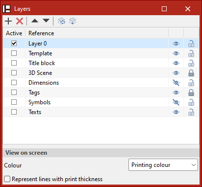
Managing and creating templates
The options in the "Templates" panel, located on the top toolbar of the sheet editor, are used to create and manage templates.

A template is a set of different drawing elements, such as lines, text and images, which can be saved as a single unit and exported to and imported into other sheets within the same project or in different projects. This saves time when drawing the sheet.
There are various ways to load a template onto a sheet:
- Upload a template directly whilst creating the sheet by selecting it when using the "New sheet" option in the "Sheets" panel.
- Load a template onto an existing sheet using the "Insert" option in the "Templates" group, as described below.
| Note: |
|---|
| Among other uses, templates can be useful for creating the title block containing general project information and, by using variables (controlled via the "Replace texts" option), specific information about the sheet, such as its number or unique reference. |
The options available in this section are as follows:
Template library
From the "Library" option, you can view and manage the templates stored in the project. These include templates created directly using the "Create" option in the same group.
On the left is a list of available "Templates", whilst on the right is a "Preview" of the selected template.
The options at the top of the list let you "Delete" and reorder templates, as well as export them to files on your hard drive and import them into other projects using the following options:
- Import the elements saved in the drive to the project
Import the templates contained in the selected .obltemplate file into the project library. - Update the elements used in the project
Update the information for the selected templates based on the information contained in the associated .obltemplate files. - Export the element to a file
Export the selected templates to an .obltemplate file on the hard drive. - File selection with initial values for the creation of a new job
Select an .obltemplate file from your hard drive. The information contained in this file will be used to automatically create the template library when creating a new project.
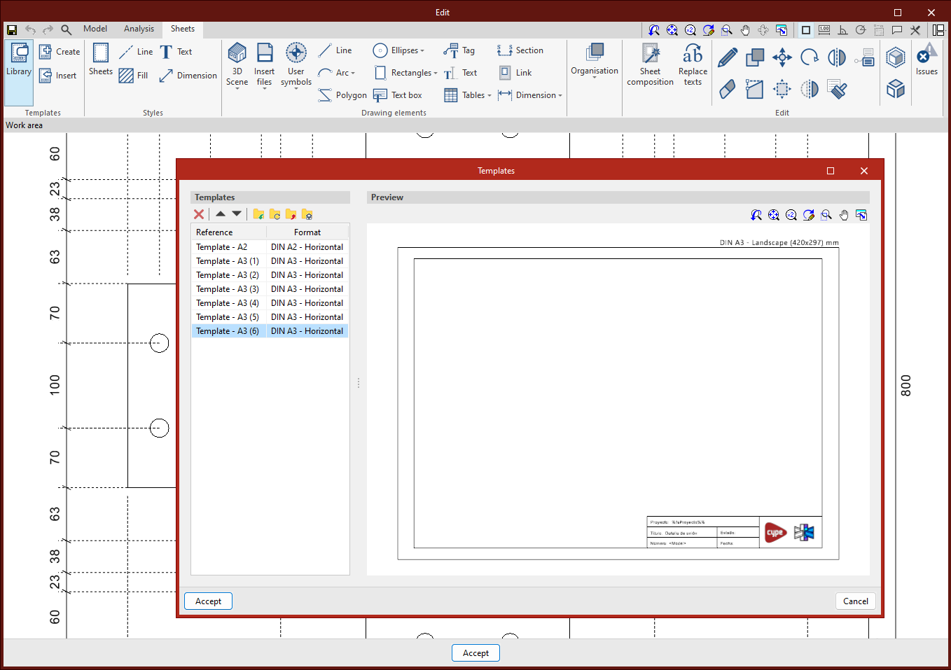
Create
The "Create" option allows you to create templates based on the information from an existing layer in the "Layers" panel of the sidebar, as follows:
- Firstly, you need to draw the template by adding all its components (text, images, lines, etc.) one by one within the same layer. You can create this layer beforehand using the "Layers" panel on the left-hand side.
- Next, click on "Create" within the "Templates" group. Here, you must enter the "Reference" name for the template and select the "Layer" on which the template was drawn.
- When you click "Accept", the template will be saved in the template library.
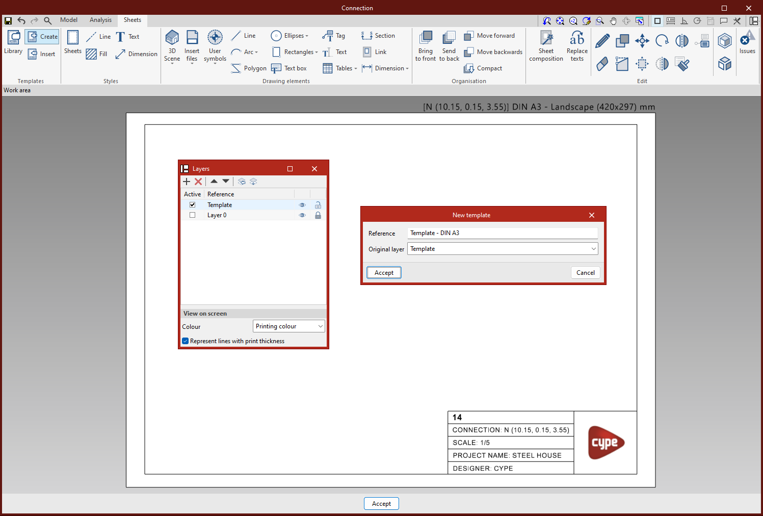
Insert
The "Insert" option allows you to load previously created templates, stored in the project’s template library, onto the sheets:
- When you click on "Insert", you must first select one of the templates from the library.
- Once you have accepted, you must specify the "Target layer" where the inserted template will be placed, and the "Import mode" (you can either "Add the template elements to the target layer" or "Empty the target layer and import the template").
By ticking the relevant box, you can "Add the styles defined in the template entities to the style libraries". - After clicking "Accept" again, the selected template will be loaded onto the specified target layer.
| Note: |
|---|
| Please note that templates are usually designed for a specific paper size, so you should insert a template that has been created for the appropriate format. |
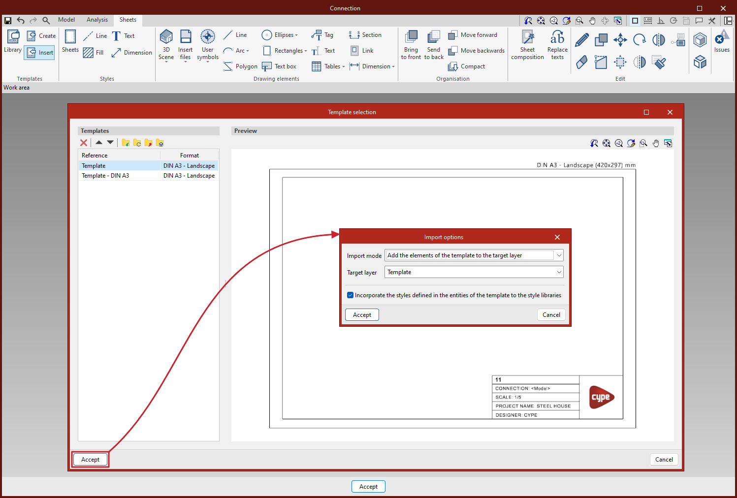
Managing styles
The options in the "Styles" panel, located on the top toolbar of the sheet editor, can be used to create custom libraries of sheets, lines, text, fills and dimensions.

The pop-up window that appears when you click on each of these options displays a list of the styles available in the project, with their parameters organised into columns.
Furthermore, using the options on the top toolbar of each style list, you can add new styles, edit them if necessary, duplicate them, delete them or reorder them in the list.
You can also export a style or a group of styles to files on the hard drive in various formats for use in other projects, as well as import them from other projects.
The styles created will be available for selection when inserting graphic elements.
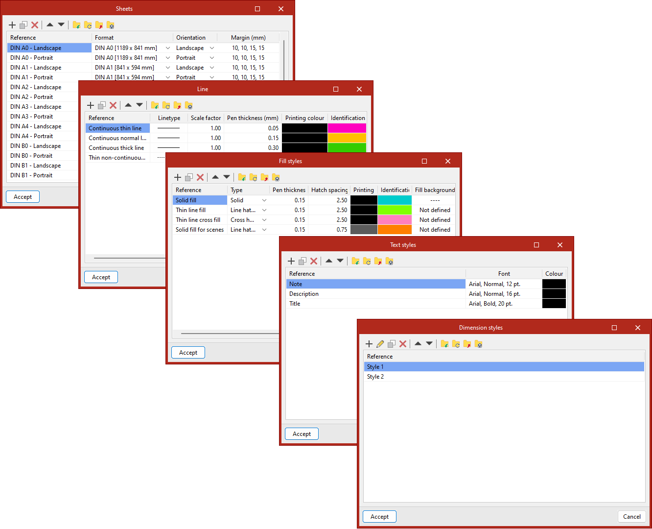
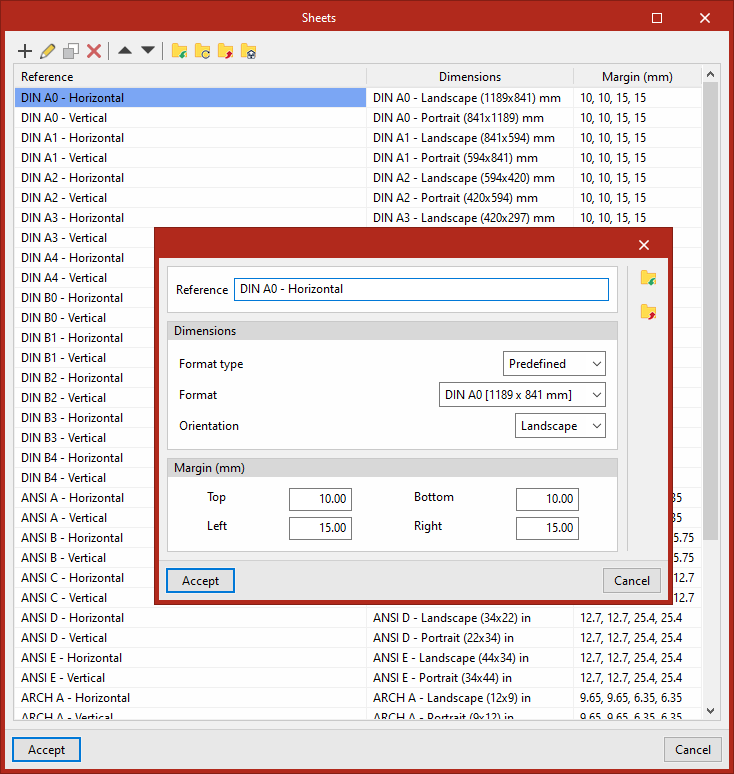
Sheets
You can configure the list of available sheet styles.
For each of the "Sheets" in the list, you can set parameters such as the format, orientation and margins:
- Reference
- Dimensions
- Format type
- Format
- Orientation
- Margin
- Top
- Left
- Bottom
- Right
Page layout styles can be saved in an .oblpage file.
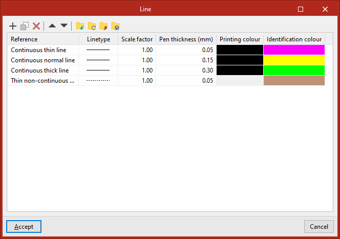
Linetype
This is used to configure the list of available line styles.
For each "Line" style, you can configure the following settings:
- Reference
- Linetype
- Scale factor
- Pen thickness
- Printing colour
- Identification colour
Line styles can be saved in an .obllinpt file.
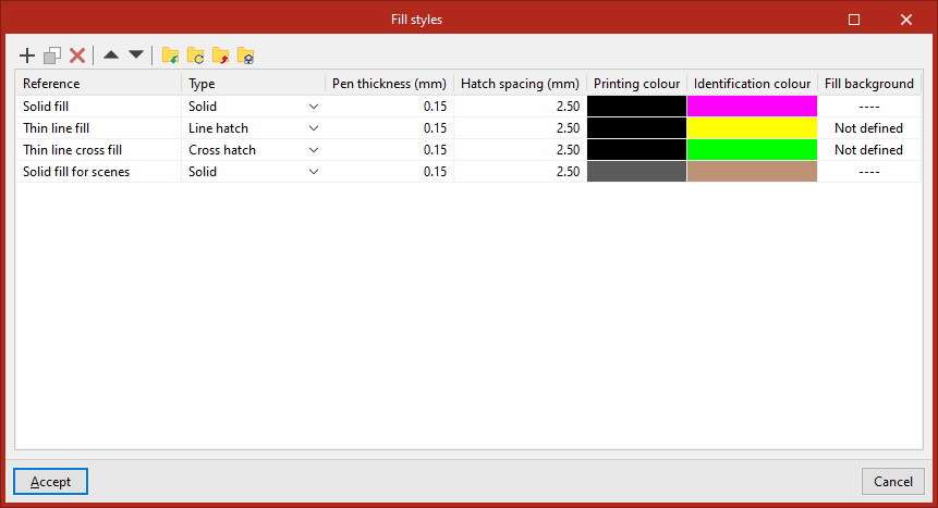
Fill styles
This is used to configure the list of available fill styles.
For each line style type under "Fill style", the following is specified:
- Reference
- Type (Solid/Line hatch/Inverted line hatch/Cross hatch)
- Pen thickness
- Hatch spacing
- Printing colour
- Identification colour
- Fill background
Fill styles can be saved to an .oblfillpt file.
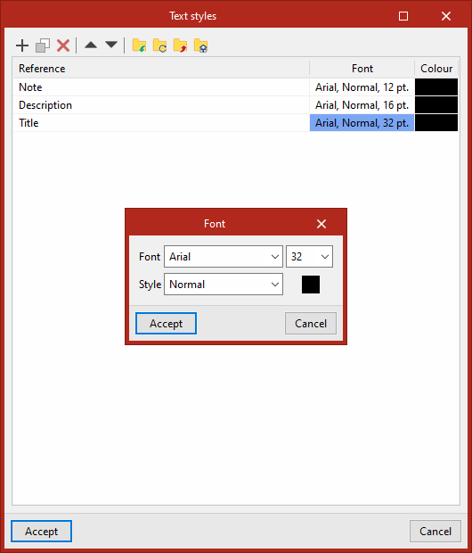
Text
This is used to configure the list of available text styles.
Each "Text" style specifies:
- Reference
- Font (including the font size and its "Style")
- Colour
Text styles can be saved in an .obltxtpt file.
Dimension
This is used to configure the list of available dimensions.
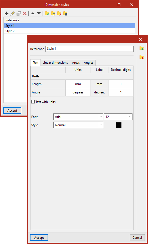
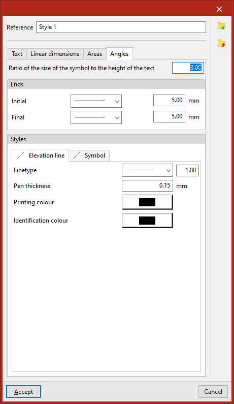
When editing each "Dimension" style, the program displays four tabs: "Text", "Linear dimensions", "Areas" and "Angles". In each of these, you can adjust parameters such as the lines and symbols to be used, or the thickness of each part of the dimensions:
- "Text" tab
Configure the text for dimensions:- Select the "Units" to be used (specifying their representative "Label" and the number of decimal places to be used) for "Length" and "Angle" measurements. When this "Text with units" option is enabled, the dimension text displays the units.
- You can also set the "Font", its size, "Style" and colour.
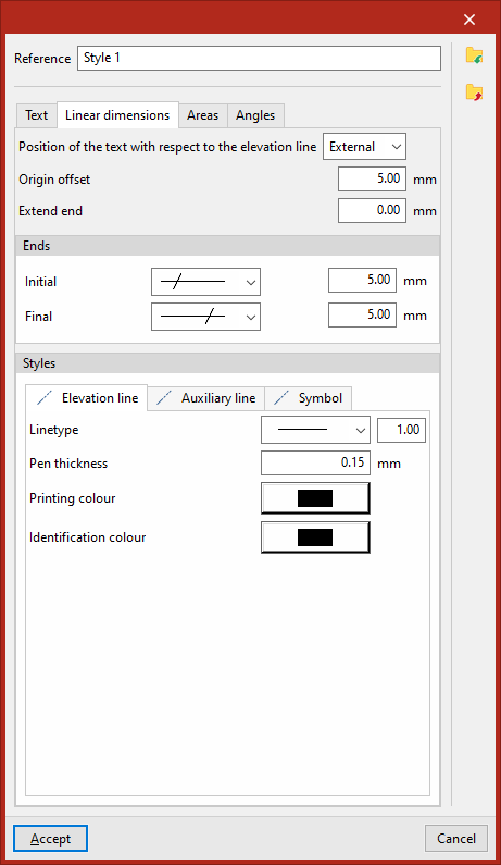
- "Linear dimensions" tab
Configure the lines and symbols used to create the dimension representation:- Specify the "Position of the text with respect to the elevation line", whether it is outside, centred or inside.
- Enter the values for "Origin offset" and "Extend end".
- Select the symbols for the "Initial" and "Final" "Ends", as well as their size
- Finally, define the "Styles" (including "Linetype", "Pen thickness", "Printing colour" and "Identification colour") of the:
- Elevation line
- Auxiliary line
- Symbol
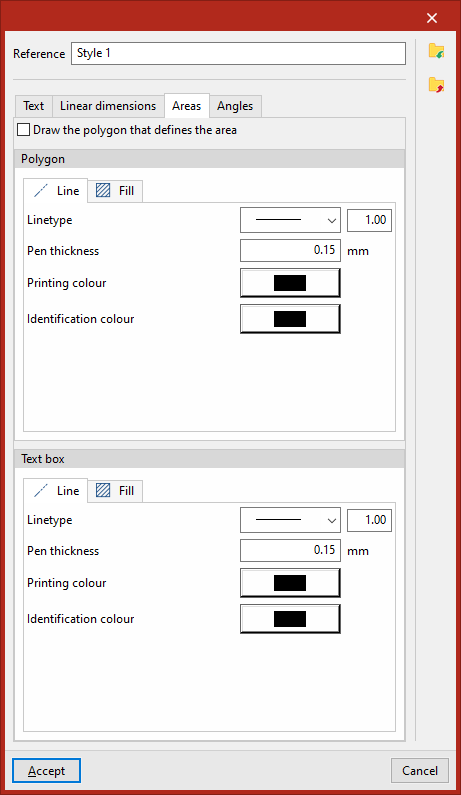
- "Areas" tab
Configure the display of area dimensions:- First, you are asked whether you want to "Draw the polygon that defines the area"
- Next, define the styles (including "Stroke", "Pen thickness", "Print colour" and "Identification colour") for:
- The "Polygon" representing the defined area, including the "Line" and its "Fill"
- The "Text box" for the area dimension, also including the "Line" and an optional "Fill".
- "Angles" tab:
Configure angle dimension elements:- Enter the "Ratio between symbol size and text height".
- Select the symbols for the "Initial" and "Final" "Ends", as well as their size.
- Finally, define the "Styles" (including "Linetype", "Pen thickness", "Printing colour" and "Identification colour") of the:
- Elevation line
- Symbol
Dimension styles can be saved in an .obllinemeasurept file.
Inserting scenes into sheets
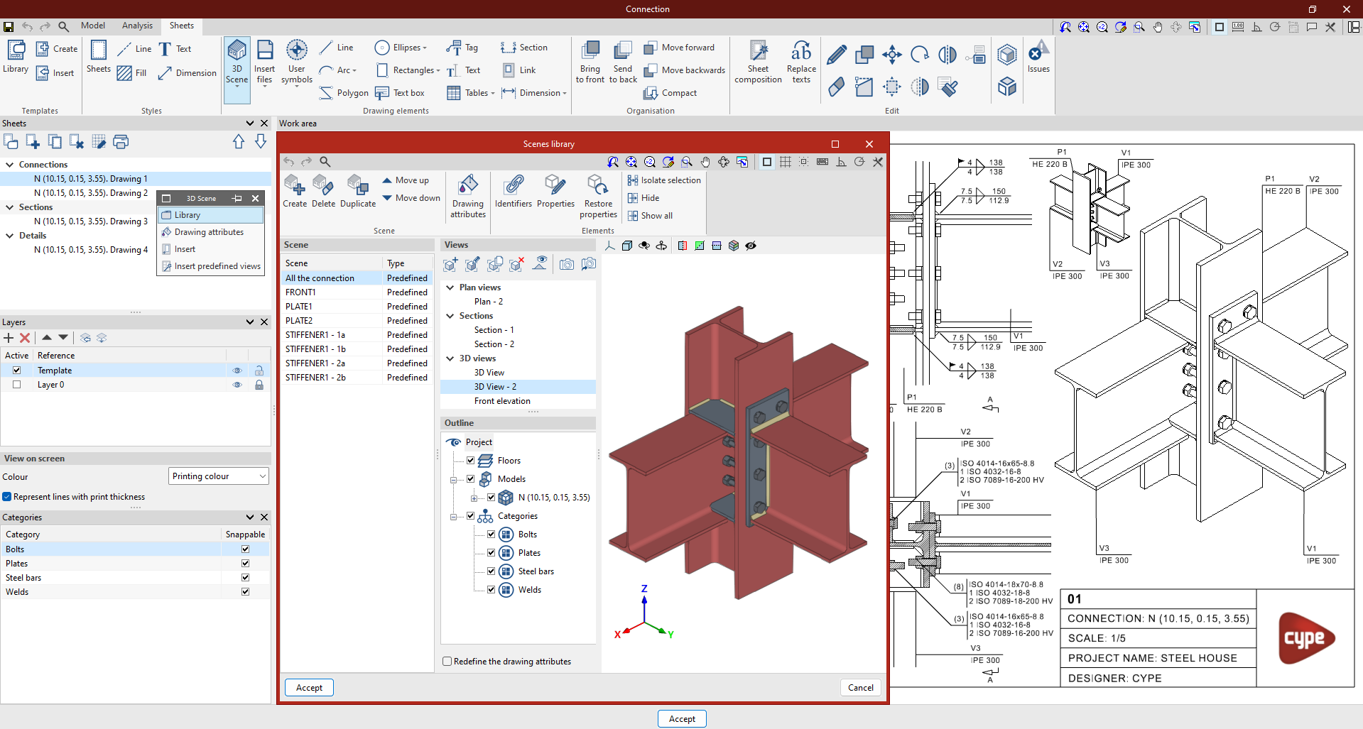
The options in the "3D Scene" menu (which is located within the "Drawing elements" section of the top toolbar) in the sheet editor let you manage the scene library and insert scenes into sheets in CYPE Connect.

The process for generating views of the model (or part of the model) and inserting them into a previously created drawing is as follows:
- Firstly, the 3D scene "Library" is used, which makes it easier to create scenes to be incorporated into the sheets. Each scene can contain several views, and you can select which elements are displayed in each one.
- The scenes are then inserted onto the drawing using the "Insert" or "Insert predefined views" options described below.
| Note: |
|---|
| The content of the drawings is linked to the model; in other words, any scenes and views that have been defined, as well as any element labels that have been entered, will be updated automatically if changes are made to the model. If the joint is exported to the "Joint library", the drawings will also be exported and can be reused in future projects. |
Insert
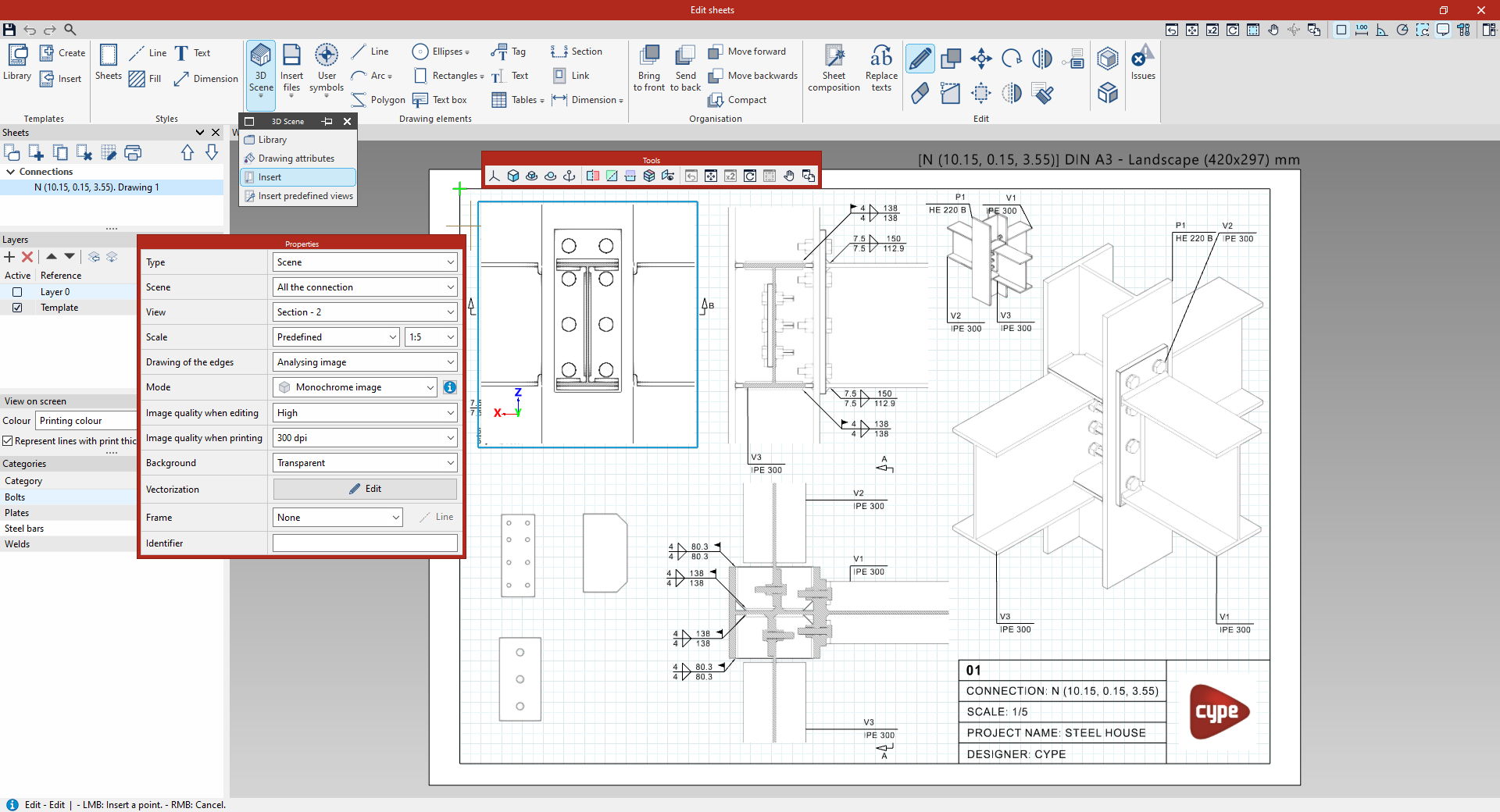
To freely insert a scene into the drawing, select the "Insert" option in the "3D Scene" menu. Then, in the workspace, draw the box where the new scene is to be inserted by selecting two corners.
Once the box has been inserted, a "Properties" panel appears. In this panel:
- Select the "Scene" and "View" you want to insert, which must have been prepared in advance in the "Scene library" (which, in turn, depends on the type of plate being edited).
- Select the "Scale", either "Depending on the zoom", a "Predefined" scale, or by entering a "Scale factor".
- Configure the "Edge drawing", either by "Analysing the image" or "Using the model’s geometry".
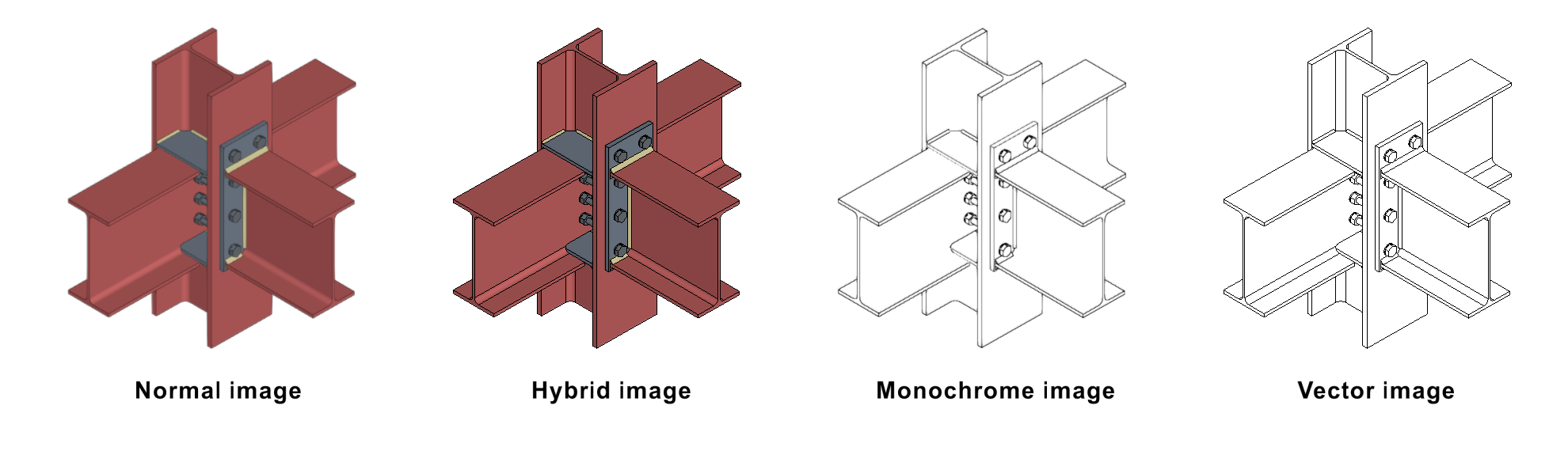
- Select the image display "Mode" from normal, hybrid, monochrome or vector.
- Select the "Image quality when editing" ("Low", "Medium" or "High") and the "Image quality when printing" (one of the various pixels per inch [ppp] values available).
- Define the "Background" ("Solid white" or "Transparent").
- Edit the "Vectorisation" options.
- Add a "Frame" if desired.
- Specify an "Identifier" for the scene.
- Edit the "Tag generation" settings.
At the same time, a "Tools" panel appears, where you can change the projection on the fly, rotate the view of the inserted scene or cut it along section planes.
Finally, after adjusting the scene properties, click outside the box to finish inserting the scene into the sheet.
| Note: |
|---|
| If necessary, you can use the "Object reference" option on the top toolbar, as well as the "Grid" on the sheet, to position the scene frame accurately on the sheet. |
Insert predefined views
The "Insert predefined views" option, within the "3D Scene" menu, can be used to automatically generate and insert predefined views of the model or part of the model into the drawings.
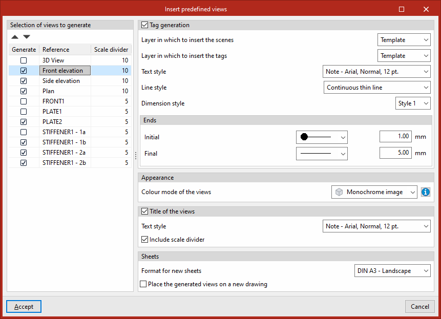
In the pop-up window that appears when you click on this option, you can configure the generation and insertion of views:
- On the left, you can "Select the views to generate" by ticking the "Generate" box for the desired views, which are identified by their "Reference", and where you can also adjust the "Scale factor".
- The configuration options on the right allow you to do the following:
- Configure "Tag generation" by selecting the "Layer in which to insert the scenes", the "Layer in which to insert the tags", the "Text style", the "Line style" and the "Dimension style", as well as selecting the symbols for the "Initial" and "Final" "Ends".
- Under "Appearance", select the "Colour mode of the views" (normal, hybrid, monochrome or vector).
- Optionally, you can add the "View title" by selecting its "Text style" and, if desired, "Include scale divider".
- In "Sheets", select the "Format for new sheets" if you need to create new drawings to insert the views, and, if desired, you can "Insert the generated views into a new sheet" rather than into the one currently visible by selecting the last option.
When you confirm, the program will generate the specified views and automatically place them on the project sheet(s).
3D scene library
The "Library" option, within the "3D scenes" menu (found in the "Drawing elements" section of the top toolbar) in the sheet editor, lets you manage the scene library in CYPE Connect.

The 3D scene library can prepare, create and configure views of the model or parts of it for later insertion into drawings, such as plans, elevations, sections and perspectives.
Scene library interface
The "Scene library" window that appears when you click on this option displays an interface with the following sections:
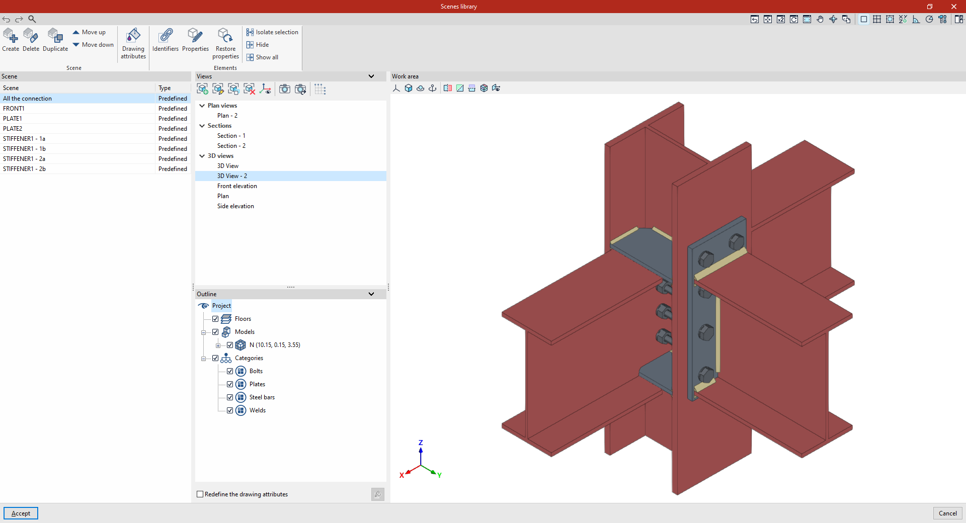
"Scene" section
On the left-hand side, in the "Scenes" section, a list of the scenes available in the library is displayed. Each scene represents the model, or part of the model, configured in a specific way, which may contain different views and display properties.
The "Scene" column displays an editable reference that lets you identify it, while the "Type" column indicates whether the scene is "Predefined" or "User-defined".
For example, in the scene library for a connection, the program may display one scene for the entire connection, and several additional scenes for each of its components.
"Views" section
In the top centre, in the "Views" section, there is a set of tools common to other CYPE programs that let you create and manage different views, including floor plans, elevations, sections and perspectives.
"Outline" section
At the bottom centre, the "Outline" section lets you show or hide the desired elements that make up the scene, including the option to do so by "Floors", "Models" or "Categories" of elements.
Work area
On the right-hand side is a 3D view of the model elements shown in the scene for the selected view.
Here, you can change the projection, rotate the model or cut it along different section planes to adjust the display for each view.
| Note: |
|---|
| The elements shown in each scene depend on the type of sheet being edited When editing sheets using the "Parts", "Assemblies", "Connections" or "Model views" (or in the "Sheets" tab of the assembly editor), only those scenes in the scene library that represent the corresponding part, assembly or assembly, or the model of the complete structure, respectively, will be available. When editing sheets using the “Composition” option, all types of scenes will be available, as indicated in the “Model” column in the scene library. In this case, it is also possible to add a “BIM Model” scene, which allows all elements imported from the BIMserver.center project to be displayed. |
Options in the "Scenes" group
In the top toolbar, the "Scenes" group includes the following options:

Create / Delete / Duplicate / Move up / Move down
These options let you manage the list of scenes available in the "Scenes" section. You can create different scenes, delete them, duplicate them or reorder them. Only user-defined scenes can be deleted.
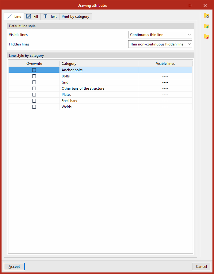
Drawing attributes
The “Drawing attributes” option lets you configure aspects such as "Line", "Fill" and "Text" styles for all scenes in the library, using the various tabs available in the window that opens when you click on this option. You can apply common default styles to all elements or apply specific styles by element category, selecting them from those available in the style libraries.
Furthermore, on the "Print by category" tab, you can select the categories of elements to be included in the final printout. Elements belonging to unchecked categories will still be displayed on the on-screen sheets, but will not be printed.
| Note: |
|---|
| You can also configure the "Drawing attributes" via the relevant option in the "3D scenes" menu, within the main interface of the sheet editor. |
These drawing attributes will apply to all scenes. If you wish to configure the drawing attributes for a specific selected scene, you can do so by ticking the "Redefine the drawing attributes" box, available under the "Outline" section at the bottom of the central panel.
Options in the "Elements" group
In the top toolbar, the "Elements" group offers the following options:

- Identifiers
Freely assign identifying text to each of the selected elements in the scene. - Properties
Edit the specific drawing properties of each of the selected elements in the scene. These include the option to "Redefine the drawing mode" of the element – whether "Normal", "Transparent" or "Wireframe" – as well as to "Redefine the section hatch" by applying a specific hatch style from those available. - Restore
Restore the drawing properties of all elements in the scene.
The following options can only be used in user-defined scenes:
- Isolate selection
Hide all elements in the scene except for the selected element, which is displayed in isolation. - Hide
Hide the selected items. - Show all
Display all the elements in the scene again, should any of the previous options have been used.
Once you have finished configuring the scenes, click "Accept".
Inserting external files
The options in the "Insert files" menu are used to insert external files, such as images and vector drawings, to supplement the project information.

This menu offers the following options:
Library
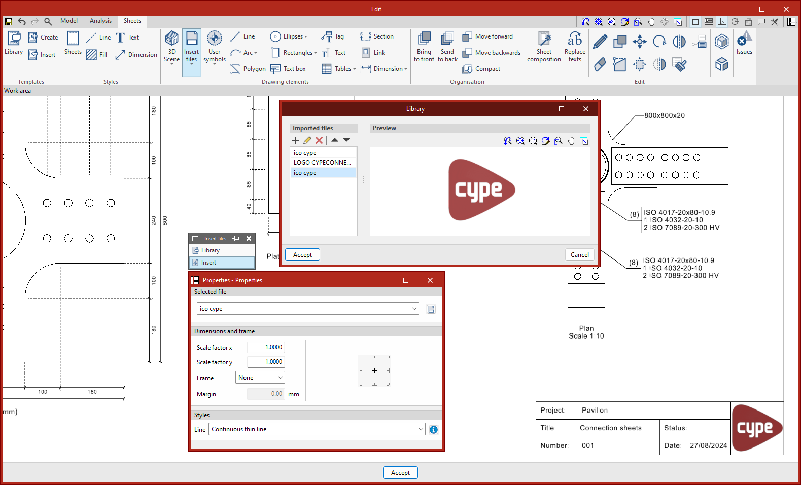
The "Library" option allows you to access the library of external files imported into the program.
The "Imported files" list is displayed on the left, and a "Preview" of the selected file is shown on the right.
To import a file, use the "Add" option at the top of the list. The program can import the following file formats: DXF, DWG, DWF, JPEG, JPG, BMP, WMF, EMF, PCX and PNG.
Insert
The "Insert" option is used to select a file from the library and insert it into the sheet.
In the "Properties" window that appears, you can configure the following settings:
- Under "Selected file", you can select a specific file from those available in the library. The option on the right can be used to access the external file library directly.
- In the "Dimensions and frames" section, you can change the size of the inserted file by entering an "X scale factor" and a "Y scale factor". Furthermore, in the "Frame" drop-down menu, you can choose not to add a border ("None") or create a "Rectangular" border around the file, in which case you must enter a value for the "Margin".
- On the right, the insertion point (either the centre, the centre of the edges or the corners) is indicated; this is where the element being inserted will be positioned.
- In the "Styles" section, you select the "Line" style for the frame, if one is being generated.
When you click on a point on the sheet in the work area, the program will insert the file.
| Note: |
|---|
| The DXF and DWF formats also import layers. Using the "Layers from inserted DXF or DWG files" option in the "Layers" section of the main interface, the program can modify the line weight and colour of the layers in these types of files. |
Creating and inserting user symbols
The options in the "User symbols" menu in the sheet editor are used to create, manage and insert user symbols (freely composed of lines, arcs, polygons, text, tables and other elements) into the sheets to supplement the project information.

This menu includes the following options:
Library
The "Library" option lets you access the library of user symbols stored within the program.
The "User symbols" list is displayed on the left, whilst a "Preview" of the selected symbol is shown on the right.
The "Edit" option at the top lets you change the position of the "Insertion point" for each symbol.
User symbols can be exported to files on the local drive for subsequent import into other projects using the other options on the top toolbar. The symbols are saved in .oblsymbol files.
Create
The "Create" option lets you create a user symbol from a selection of elements such as lines, arcs, polygons, text and/or tables previously placed on the sheets.
Once you have selected the elements that make up the symbol, you must enter a "Reference". When you confirm, the symbol you have created is saved in the symbol "Library".
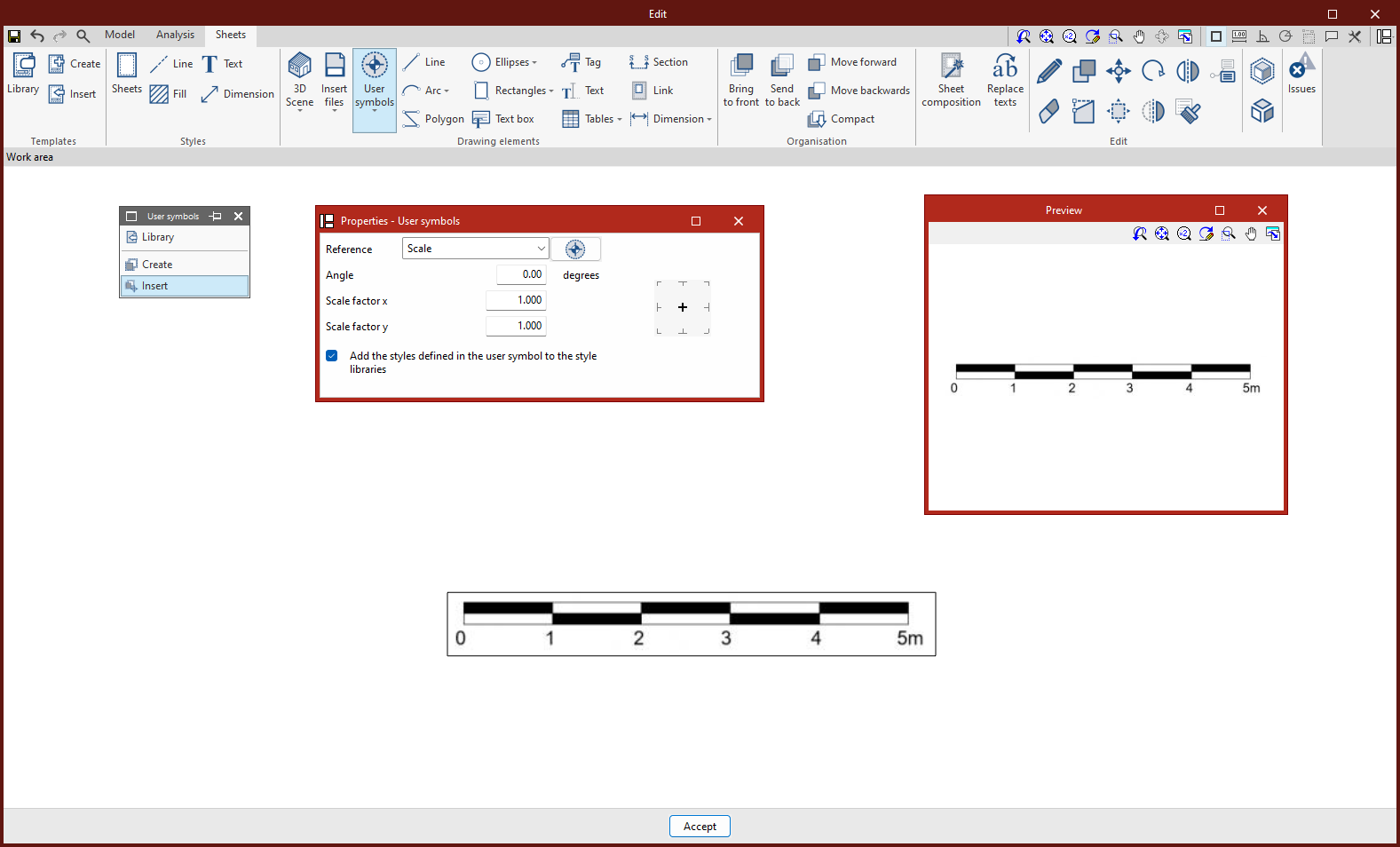
Insert
The "Insert" option lets you insert a user-defined symbol from those available in the symbol library.
To do this, in the "Properties – User symbols" window that appears when you use this option, you must select the symbol by specifying its "Reference". The program also lets you apply an "Angle", an "X-scale factor" and a "Y-scale factor" when inserting the symbol. Optionally, you can "Include the styles defined in the user symbol in the style libraries" by ticking the relevant box.
To position the symbol on the sheet, select a point in the work area.
Drawing tools
The "Drawing elements" section, located in the top toolbar of the sheet editor, provides tools for drawing lines, arcs, polygons, ellipses and rectangles, which can be drawn within the sheet area.

The available options are as follows:
| Line | Draw consecutive segments on the drawing, which can be straight lines or arcs (by selecting the "Line", "Arc given 3 points" or "Arc given the start, centre and end" options). You can also choose symbols for the "Ends" ("Initial" and "Final"), as well as select one of the available line "Styles". | 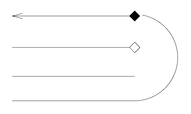 |
| Arc | Draw "3-point" arcs or arcs "Given the centre, start and end". You can also choose symbols for the "Ends" ("Initial" and "Final"), as well as select one of the available line "Styles". | 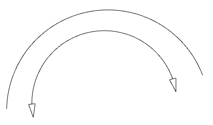 |
| Polygon | Draw polygons consisting of straight or curved segments (by selecting, for each "Segment", the option "Line", "Arc given 3 points", or "Arc given start, centre, end"). They can be filled. The program therefore lets you select "Line" and "Fill" styles. By ticking the "Draw perimeter" box, you can draw the polygon's perimeter. | 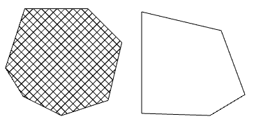 |
| Ellipses | Draw circles and ellipses (using the "Circle" and "Ellipse" options in the menu). They can be filled. The program lets you select the "Line" and "Fill" styles. By ticking the "Draw perimeter" box, you can draw the perimeter of the circle or ellipse. | 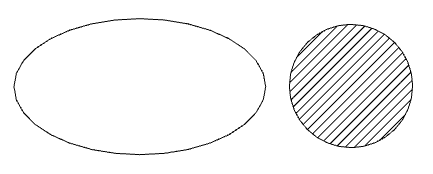 |
| Rectangles | Draw rectangles with "Straight corners" or "Rounded corners" (in which case you must enter the "Radius" of the corner curvature). They can be filled. The program lets you select the "Line" and "Fill" "Styles". By ticking the "Draw perimeter" box, you can draw the perimeter of the rectangle. | 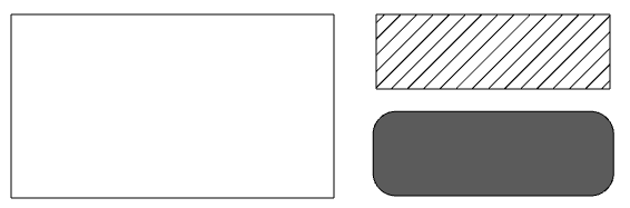 |
Inserting and editing text boxes
The following option, within the "Drawing elements" section of the top toolbar in the sheet editor, lets you insert text boxes into the sheets:

Text box
Using the "Text box" option, you can insert a box containing the text of your choice.
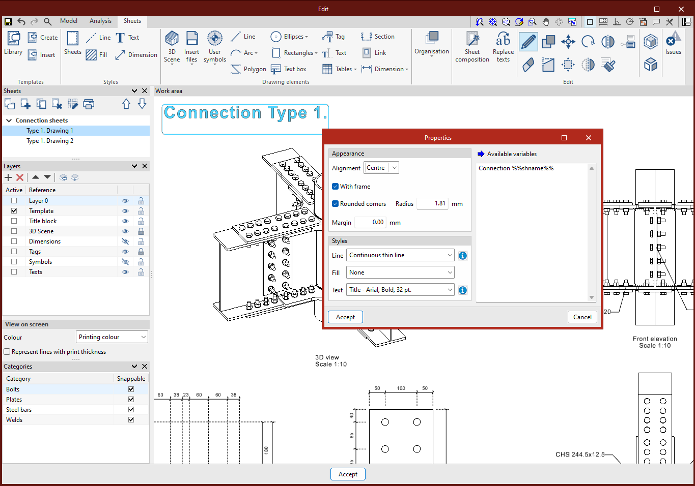
Clicking on this option will open a pop-up window ("Properties") containing the configuration options.
In this window, you can choose:
- In the "Appearance" section
The "Alignment" or positioning of the text ("Left", "Centre" or "Right"), whether you wish to display a border (by ticking the "With frame" box), with or without "Rounded corners", and the "Margin" relative to it. - In the "Styles" section
Select the style for the text you want and, where applicable, those for the line and the fill.
Next, left-click on a point on the work area and click again on a second point to set the dimensions of the box in which the text will be placed.
A new window will then open, in which you can type the text you require. Here, you can enter text linked to any of the "Available variables". Once you have finished entering the text, click the green confirmation button to complete the process.
Tagging elements
The following option, within the "Drawing elements" section of the top toolbar in the sheet editor, lets you insert tags:

Tag
Tags are used to extract information from BIM model elements included in 3D scenes. The information in the tags is linked to the model and gets updated automatically if there are any changes to it.
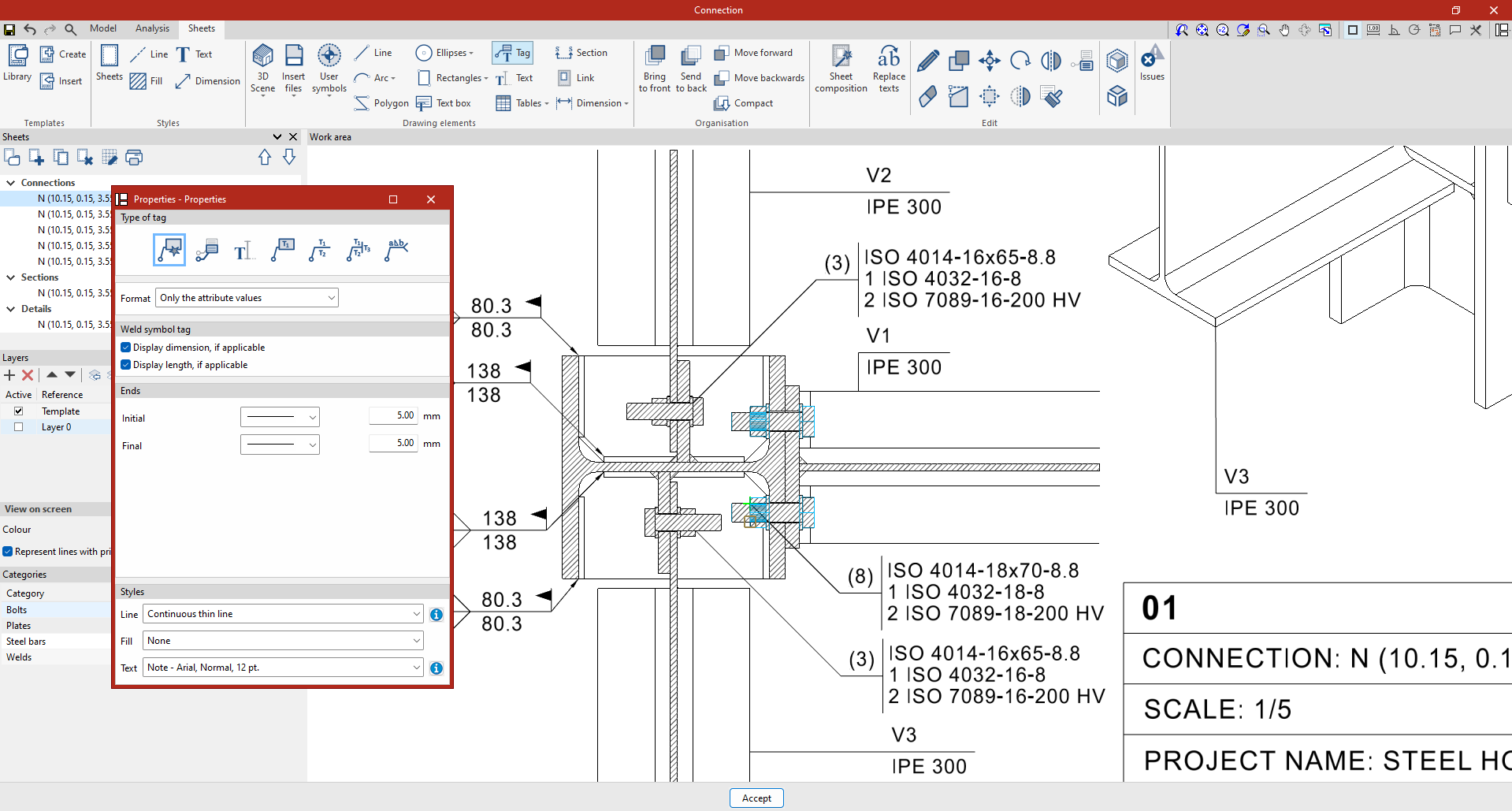
To insert a "Tag", click on this option and then on an element within a 3D scene previously inserted onto the drawing sheet. The program will automatically detect the element and extract the data associated with it to complete the tag information. Then, click anywhere on the work area to position the tag.
The "Properties" window that appears when you select this option allows you to set:
- The "Type of tag", which may be:
- "Automatic" (in which case, the program will select the appropriate tag type based on the selected element)
- From another tag (which must be selected)
- Tag with text
- Tag with two vertical texts
- Tag with three pieces of text: two vertical and one horizontal.
- Weld symbol tag (which has a separate settings panel for the symbols and data relating to the tagged weld).
- The elements to which the specified "Format" applies ("The name and values of the attributes" or "Only the attribute values").
- The "Line", "Fill" and "Text" "Styles".
- In some cases, you will need to specify the symbols for the "Ends" of the line and the "Position and frame" of the text.
| Note: |
|---|
| If you edit a tag (using the "Edit" option in the "Edit" group), you can manually change the tag text so that it is not linked to the data of a specific element. To do so, simply delete the automatically generated text containing variables (the program retrieves the properties of the model element using 'this' variables) and enter your own text freely in the corresponding field. |
Entering and editing text
The following option, within the "Drawing elements" section of the top toolbar in the sheet editor, lets you insert text into the sheets:

Text
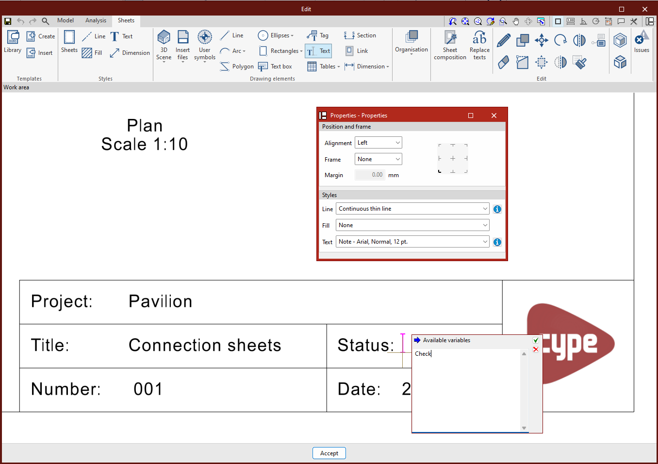
This allows you to insert text. Clicking on this option will open a pop-up window ("Properties") containing the configuration options.
In this window, you can choose:
- From the "Positioning and frame" section:
The "Alignment" or positioning of the text ("Left", "Centre" or "Right"), whether you wish to include a frame (by ticking the "Frame" box), and the "Margin" relative to it. - From the "Styles" section:
The desired text style and, where applicable, the line and fill styles.
Next, left-click anywhere on the work area to specify the text position.
A new window will then open, where you can type the text you want. Here, you can enter text linked to any of the "Available variables". Once you have finished entering the text, click the green confirmation button to complete the process.
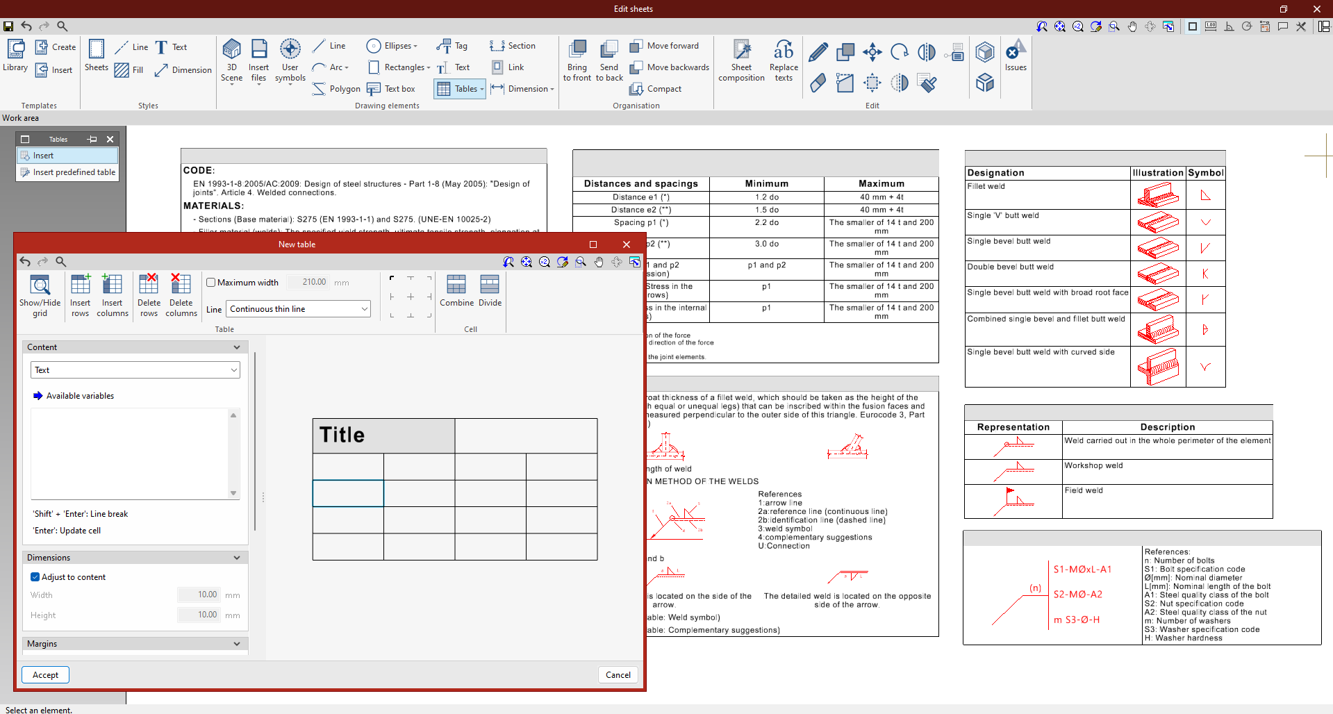
Entering tables
The options in the following menu, available within the "Drawing elements" group on the top toolbar of the sheet editor, let you insert tables into sheets:

Tables
The program allows you to create tables from scratch (using the "Insert" option), as well as to "Insert predefined tables", which depend on the type of sheet being edited. As follows:
- On the parts drawings, a "Table displaying the use of the part in the assemblies" may be included,
- On the assembly drawings, a "Table of assembly parts" can be included.
From the editing panel for each table (accessible via the "Edit" option or when inserting a table from scratch), you can manage the content text, dimensions, margins, paragraph style, and the borders and shading of table cells, as well as the table’s rows and columns and their line styles.
Creating sections from views
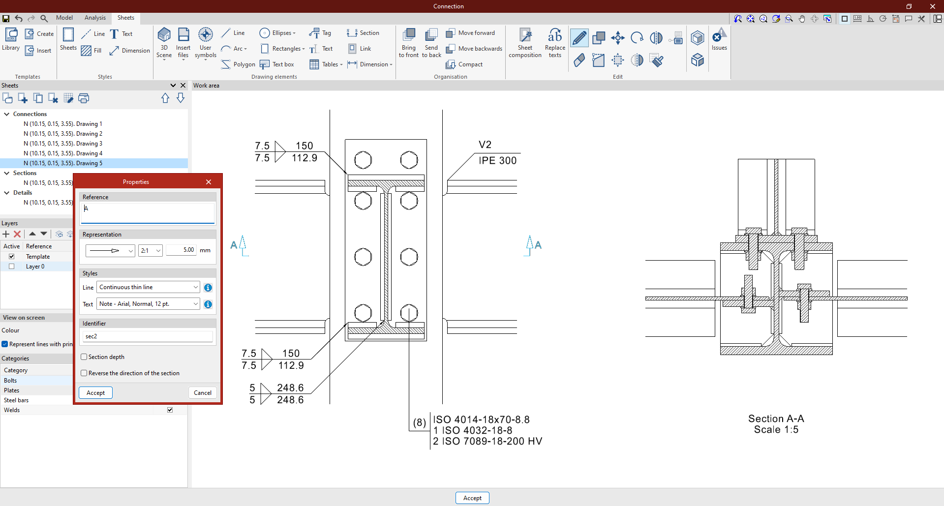
The following option, within the "Drawing elements" section of the top toolbar in the sheet editor, lets you generate and insert sections from views:

Section
This option generates sections from a 3D scene that has already been inserted into the drawing.
To do this, first click on "Section". In the "Properties" window, specify the numbering (this can be "Automatic numbering" by ticking the relevant box), the "Display" symbol, and the "Line" and "Text" styles for the section you wish to create.
Next, you must specify the precise location of the section view within an existing scene by selecting two points in the work area. The corresponding section view will be created automatically and can be positioned on the drawing at the point specified by the user.
Inserting links
The following option, within the "Drawing elements" section of the top toolbar in the sheet editor, lets you insert a link to one sheet within another.

Link
This option inserts links that display the content of one sheet within another.
To do this, follow these steps:
- Clicking on this option opens a window where you can "Select the sheet to insert". Here, a list appears showing the name of the "Model" displayed on each sheet, the "Name" of the sheet and the "Group" to which it belongs, as well as an indication of whether it is already "Linked to the current sheet". On the right-hand side, a "Preview" of the sheet is displayed.
- After selecting the desired sheet and clicking "Accept", move the mouse to position the link on the work area and left-click to insert it at the desired location.
- The sheet selection window reopens automatically so that you can add further links to the same sheet in succession. This allows you to create compositions that include, for example, a graphical representation of an assembly and its parts on the same sheet, or a view of the model alongside details of different connections.
- When you have finished, close the sheet selection window to complete the operation.
When you link content, any changes to the source sheet will be automatically updated on the sheet containing the link. Furthermore, if a link is edited, the program will automatically select the source sheet.

Dimension
The "Dimension" menu, within the "Drawing elements" section of the top toolbar in the sheet editor, offers options that allow you to dimension the scenes in a project in order to generate all the necessary information for the drawings.

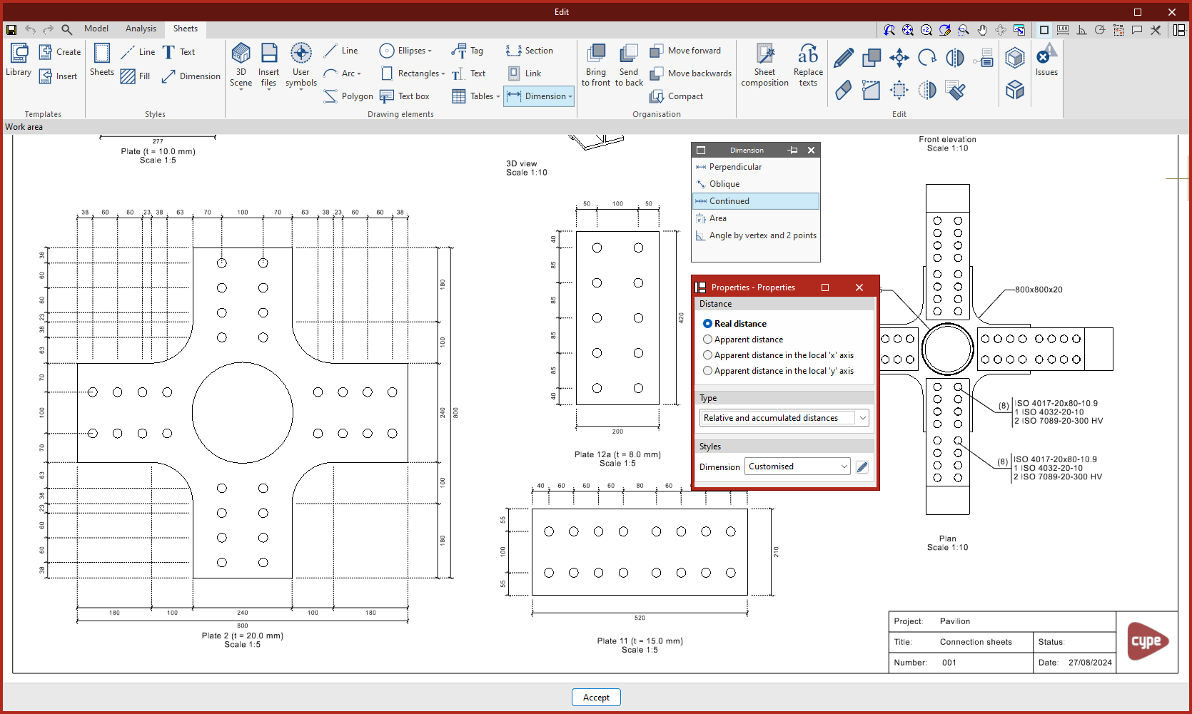
This menu displays the following options: "Perpendicular", "Oblique", "Continued", "Area" and "Angle by vertex and 2 points".
Perpendicular dimensions
The "Perpendicular" option allows you to enter perpendicular dimensions. To do this, select the two points that define the distance to be dimensioned and then position the dimension at the desired point in the workspace. The program will draw the dimension lines perpendicular to the dimensioned distance.
Oblique dimensions
The "Oblique" option allows you to enter oblique dimensions. To do this, after selecting the two points for the distance to be dimensioned, define the direction in which you want the dimension lines to be drawn (by selecting two more points in the work area); then, click on a point to position the dimension.
| Note: |
|---|
| When using the oblique dimensioning option, make sure you turn off the "Orthogonality" option, located in the top right-hand corner of the interface. |
Continued dimensions
The "Continued" option allows you to enter a series of continued dimensions by selecting several points.
The program offers three types of continued dimensions:
- Relative distance
The dimension shows only the distances between the marked points. - Accumulated distance
The contour line shows only the accumulated distance from the first point to the various marked points. - Relative and cumulative distances
The elevation mark shows both types of distance.
Relative distances are shown on the dimension line, whilst accumulated distances are indicated by text perpendicular to the dimension line.
Real and apparent distance
In the "Properties" window that appears when you use the "Perpendicular", "Oblique" or "Continued" options, the following methods of measuring distances are available:
- Real distance
The actual three-dimensional distance between the points marked on the model is measured. - Apparent distance
This is measured as the projection of the actual distance between the points onto the plane of vision. - Apparent distance in the local 'x' axis
This measures the projection of the actual distance between the points onto the view’s local 'x' axis. - Apparent distance in the local 'y' axis
This measures the projection of the actual distance between the points onto the view’s local 'y' axis.
| Example: |
|---|
| The real distance is the projection of the actual distance onto the plane of a given view. For example, in a plan view showing a sloping element with an actual length of 2 m and a gradient of 30 per cent, the real distance is 2 m, and the apparent distance (measured on the horizontal plane) is 1.92 m. |
In addition, the "Styles" dimension must be selected.
Surface area dimensioning
The "Area" option is located within the "Dimension" option on the top toolbar.
This feature allows you to measure surfaces in the 3D scene and display their area as text.
In the "Properties" window that appears when you select this option:
- Specify whether the "Plane to calculate the area" is:
- The "Global XY plane in the z-coordinate of the first point"
- The "Plane defined by all the points"
- Select whether each "Segment" is a "Line", an "Arc defined by 3 points", or an "Arc defined by start, centre and end"
- Select the dimension "Styles"
Angle dimensioning
Using the "Angle via vertex and 2 points" option, you can constrain any angle on the plane.
In the "Properties" window that appears when you select this option:
- Specify whether the "Angle" to be measured is:
- The "True angle" between the elements of the model
- The "Apparent angle" in the projection of the view
- Select the dimension "Styles"
Organisation tools in the sheet editor
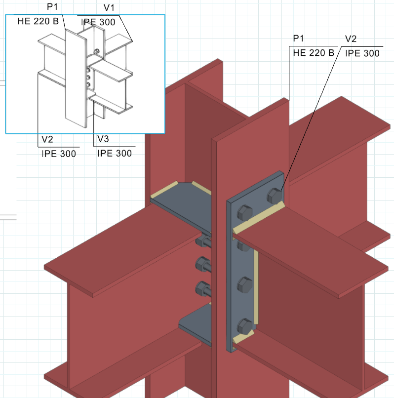
The options in the "Organisation" section, located on the top bar of the sheet editor, let you manage the drawing order (or stacking order) of elements. This is useful when elements occupy the same position on the sheet, resulting in visual overlaps.

The available options are as follows:
- Bring to front
Set the selected element to the highest z-index, ensuring it is always visible. - Send to back
Set the selected element to the lowest z-index, so that it is hidden by any other element overlapping it. - Move forward
Each time you click this option, the program moves the selected item up one level in the stacking order. - Move back
Each time this option is pressed, the program moves the selected item down one level in the stacking order. - Compact
Compact the stacking order of the elements, maintaining the relative spacing between the levels occupied by elements and removing empty levels that are not in use, which may have been created by repeatedly selecting the previous options. We recommend using this option if you reach a point where you are repeatedly using the "Move forward" or "Move back" options without seeing any changes.
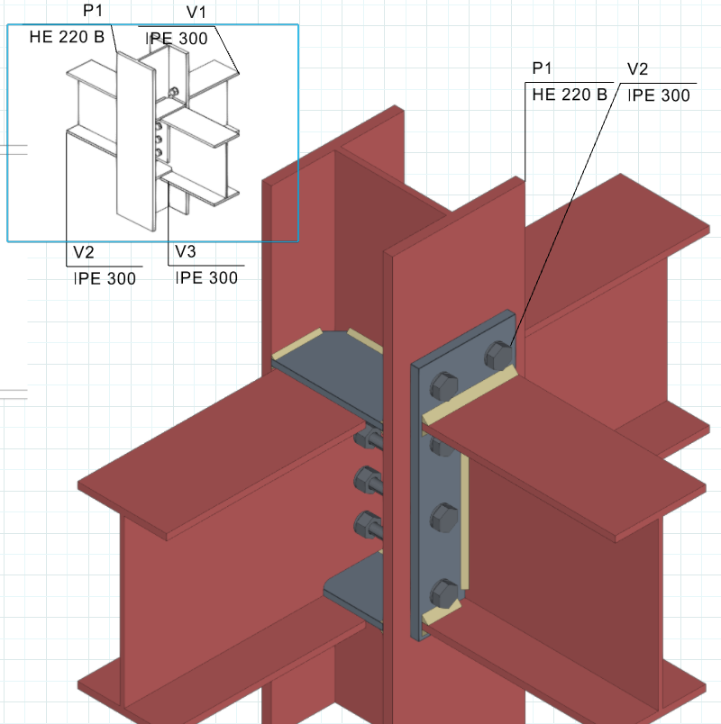
Reorganising two overlapping scenes
Automatic sheet composition
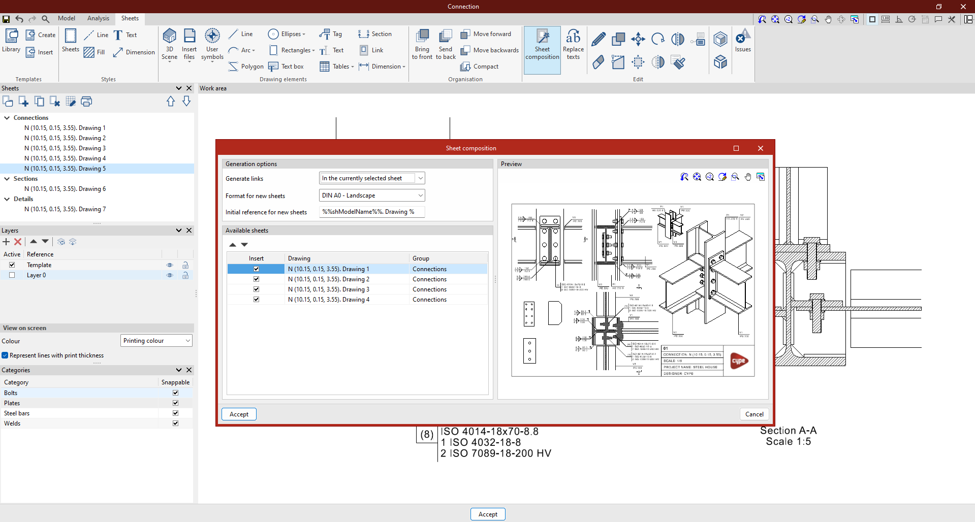
The following option, within the "Edit" section of the top toolbar in the sheet editor, allows you to automatically generate a collection of drawings from a selection of sheets. Each drawing is inserted as a link to the content of the corresponding source sheet.

Sheet composition
This option allows you to automatically generate a set of links to other sheets.
To do this, once you have clicked on the option, the "Sheet layout" window will appear, where you should do the following:
- Firstly, configure the "Generation options". To do this, you specify whether to "Generate links" "In the currently selected sheet" or "In a group of sheets". Next, specify the "Format for new sheets" and the "Initial reference for new sheets".
- The table below then shows a list of the "Available sheets" in the project, including the name of the "Model" displayed on each sheet, the "Name" of the sheet and the "Group" to which it belongs. Here, tick the boxes on the left to indicate which sheets you wish to "Insert" into the new layout.
- A "Preview" of each selected sheet is shown on the right.
Once you click "Accept", the program will generate links to the selected sheets and automatically arrange them on the drawing in a mosaic layout.
Replacing texts
The "Replace texts" option, within the "Editing" section of the top toolbar in the sheet editor, lets you create and view the variable texts available in the program.

The use of variables allows keywords to be replaced with specific project data. For example, if the character string %%shname%% – corresponding to one of the predefined variables – is entered into a text field or text box, the program will replace this text at the time of printing with the value assigned to that variable; in this case, the "Reference" of the sheet.
In this way, the use of variables can be useful for centralising the editing of project data (for example, by using them in the text boxes on the sheets), thereby avoiding duplication of work or the need for additional editing on each text.
There are two types of text substitution variables: "User variables" and "Predefined variables". Both can be managed or viewed in the two tabs with the same names in the "Replace texts" pop-up window, which appears when you click on this option.
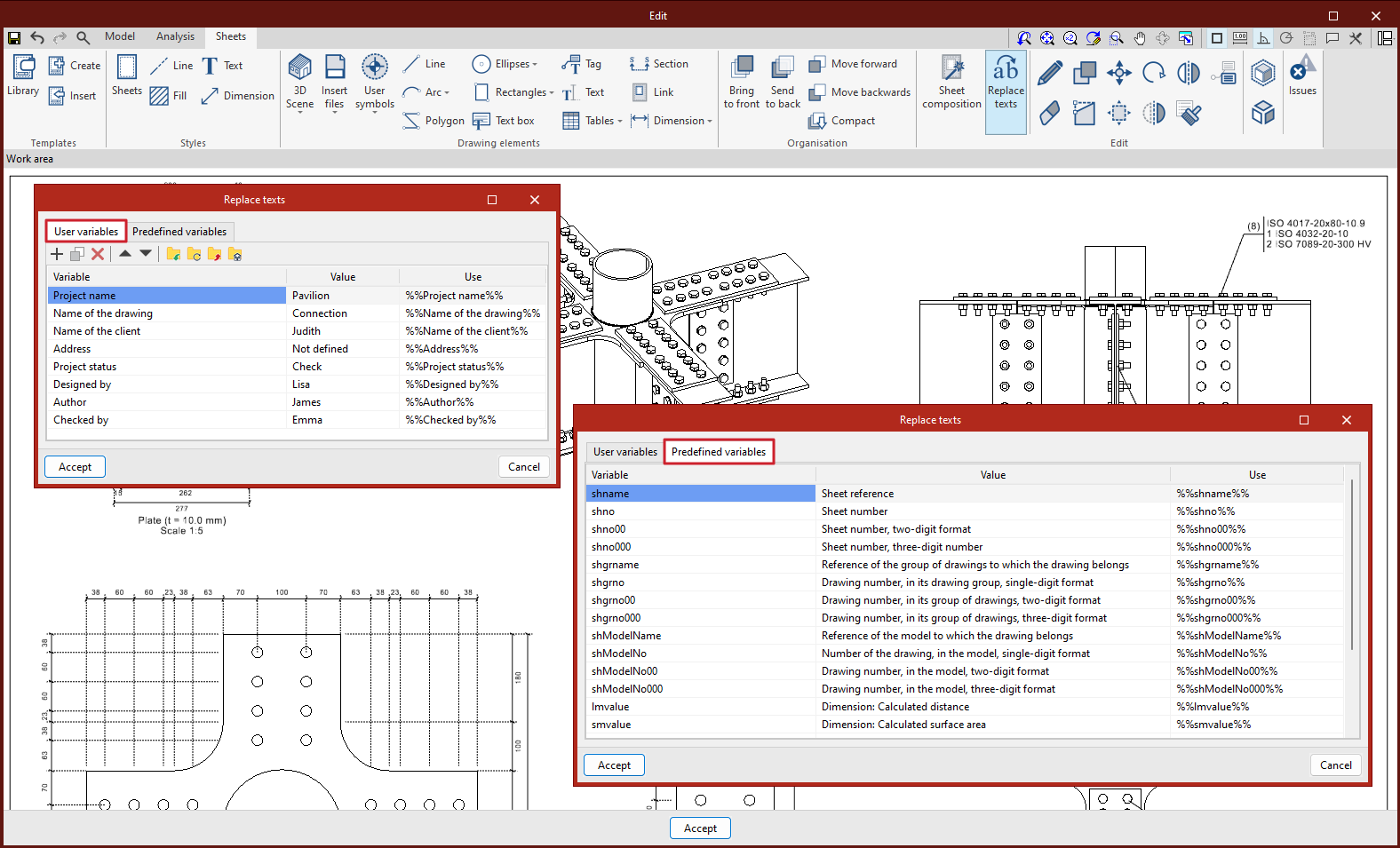
User variables
User variables let you freely create customised variable text that you can reuse in other drawings or projects. These variables may include the project name, the address, the architect and engineer in charge, and so on.
To do this, in the list displayed in the "User variables" tab of the "Replace text" window, you must "Add" each variable as a separate entry, entering:
- The identifier for the "Variable"
- Its "Value", or the text you wish to display in print
- In the "Use" column, the program displays the string that must be entered into any text field to call each variable
User variables can be exported to files in .oblvartxt format, which can be saved locally so that they can be loaded later into other projects. This is done using the export and import options at the top of the screen.
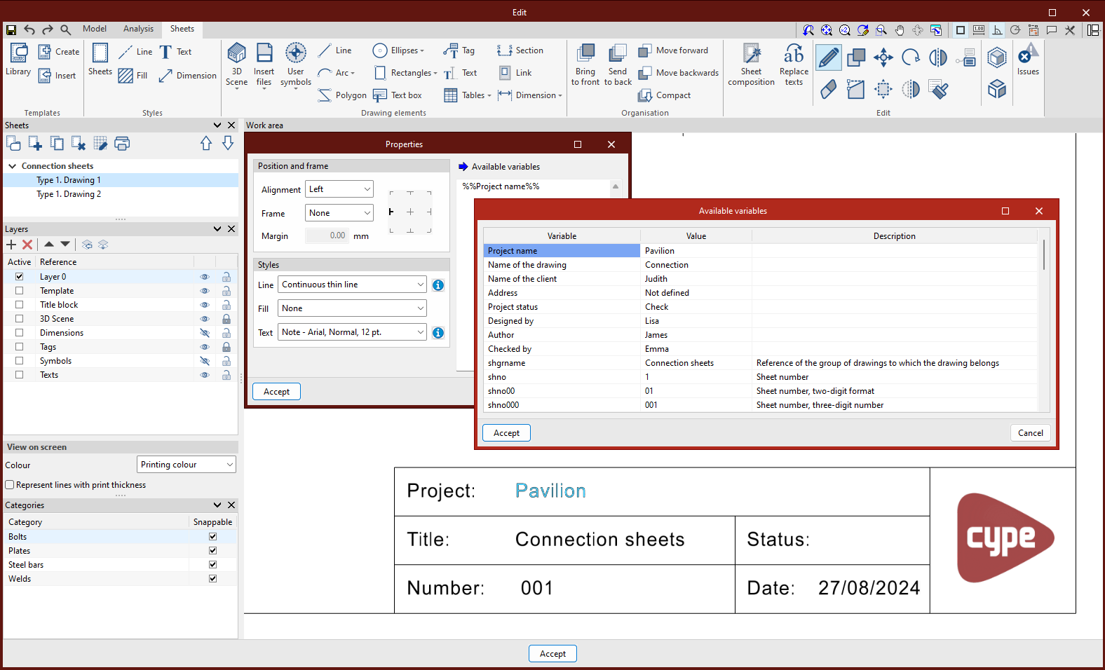
Predefined variables
Predefined variables are a set of variable text fields available by default in the program, which read various project data such as the sheet reference, the sheet number, the scale factor, etc.
The program allows you to view the list of "Predefined variables" in the relevant tab of the "Replace text" window, including:
- The identifier for the "Variable"
- Its "Value", or the information to be displayed in print
- In the "Use" column, the program displays the string that must be entered into any text field to call each variable
In addition, there are other predefined variables that the program uses in tags and dimensions to extract information from the model associated with scenes and views. This allows the program to dynamically link the information displayed in the text of these tags or dimensions to specific model parameters, which can be modified whilst editing. These variables can be accessed via the "Available variables" option, which appears next to each text field.
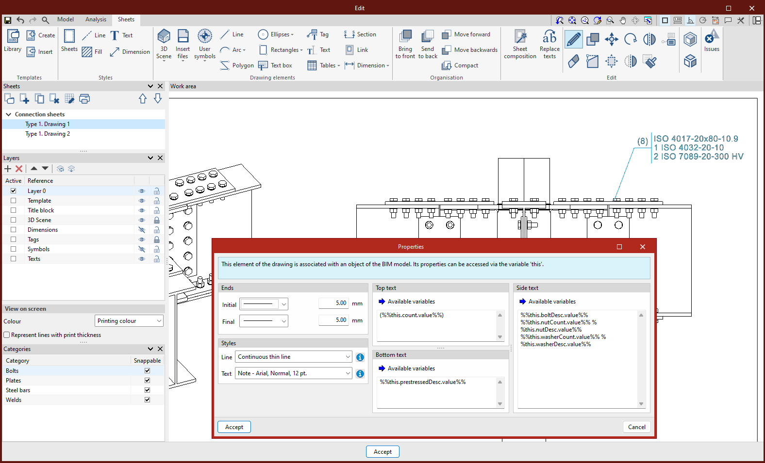
List of predefined variables
The variables displayed in the "Predefined variables" tab are as follows:
| Variable | Value | Use |
| shname | Sheet reference | %%shname%% |
| shno | Sheet number | %%shno%% |
| shno00 | Sheet number, two-digit format | %%shno00%% |
| shno000 | Plate number, three-digit format | %%shno000%% |
| shgrname | Reference number of the sheet group to which the sheet belongs | %%shgrname%% |
| shgrno | Sheet number, within its group of sheets, single-digit format | %%shgrno%% |
| shgrno00 | Sheet number, within its group of sheets, in two-digit format | %%shgrno00%% |
| shgrno000 | Sheet number, within its group of sheets, three-digit format | %%shgrno000%% |
| shModelName | Model reference for the sheet | %%shModelName%% |
| shModelNo | Sheet number, within the model, single-digit format | %%shModelNo%% |
| shModelNo00 | Sheet number, within the model, two-digit format | %%shModelNo00%% |
| shModelNo000 | Sheet number, within the model, in three-digit format | %%shModelNo000%% |
| lmvalue | Dimension: Calculated distance | %%lmvalue%% |
| smvalue | Dimension: Calculated surface area | %%smvalue%% |
| {sceneViewId}.modelName | Model reference shown in the scene | %%{sceneViewId}.modelName%% |
| {sceneViewId}.scnName | Scene reference | %%{sceneViewId}.scnName%% |
| {sceneViewId}.viewName | Scene view reference | %%{sceneViewId}.viewName%% |
| {sceneViewId}.scaleF | View scale factor | %%{sceneViewId}.scaleF%% |
| etqFirstPointZ | 'z' coordinate of the label’s starting point, relative to the scene | %%etqFirstPointZ%% |
| etqFirstPointZUds | 'z' coordinate of the label’s starting point, relative to the scene, in units | %%etqFirstPointZUds%% |
Editing tools in the sheet editor
The "Edit" section of the main toolbar in the sheet editor contains the tools for editing the elements arranged in the workspace (graphic elements, scenes, etc.).

The options in this section are as follows. The key combinations that provide direct access to some of these tools are shown in brackets:
 | Edit (Alt+E) | Edits the parametric properties of the selected element in the workspace. |
 | Delete (Alt+D) | Deletes a previously entered element. |
 | Copy (Alt+C) | Create a copy of one or more elements. |
 | Modify geometry (Alt+G) | Modify the points that define the geometry of an element one by one. |
 | Move (Alt+M) | Moves the selected element completely from one point to another. |
 | Redesign | Redesign an element in the selected direction or in both directions simultaneously. |
 | Rotate (Alt+R) | Rotate an element in the plane by entering the centre of rotation and specifying the angle of rotation. |
 | Symmetry (Alt+S) | Moves a selection of elements symmetrically about an axis defined by two points. |
 | Copy with symmetry | Copy a selection of elements that are symmetrical about an axis defined by two points. |
 | Assign properties | Matches the parametric properties of the selected element to those of other elements. |
 | Copy content from tags | Copy the content of one tag to other tags. |
 | Group | Groups the selected elements. Operations can be carried out on the resulting group so that they affect all its components as a whole. |
 | Ungroup | Undoes the grouping of elements carried out in the previous step. |
 | Show/Hide issues | Enable or disable the display of issues, warnings or errors about elements that are experiencing a problem. When you hover the cursor over the issue icon, the program provides details about the situation. |
Results output (sheet editor)
Once the sheets for the project have been set up, you can print them. To do this, click the "Print" button on the top toolbar of the "Sheets" panel, located on the left-hand side of the sheet editor interface.
This opens the "Print" pop-up window, in which the following settings are configured:
- Firstly, the list of available sheets is displayed, showing their "Reference", the "Group" to which they belong and their "Format". Select the sheets you wish to "Print" by ticking the box in the left-hand column. In the "Status" column, the program indicates whether there is an issue with the sheet (for example, if any of the elements entered are outside the sheet’s print area).
- In the lower drop-down menus, you can select the "Printing device". Here, the program lets you export the generated drawings to PDF, DWG or DXF files, or print them directly by selecting one of the printers available on the system.
- Furthermore, under "Export mode", you can choose between exporting "All the sheets on the same file" (in which case you enter the "File name" and specify the folder where it will be saved), or "Each sheet on a file" (in which case, you select the "Folder" where the files will be stored).
- In "Export scene views", the program also lets you export scene views "As a raster image" or "As a vector image (when possible)".
- The last box lets you "Show with associated program" for the files generated.
When you click "Accept", the program will print the sheets or save the files in the selected formats to the specified location.
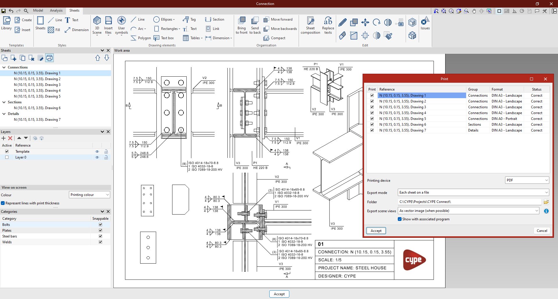
Table of contents
Complete your tour of CYPE Connect by exploring the other sections available:
