Inserting scenes into sheets
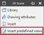
The options in the "3D Scene" menu (which is located within the "Drawing elements" section of the top toolbar) in the sheet editor let you manage the scene library and insert scenes into sheets in CYPE Connect.

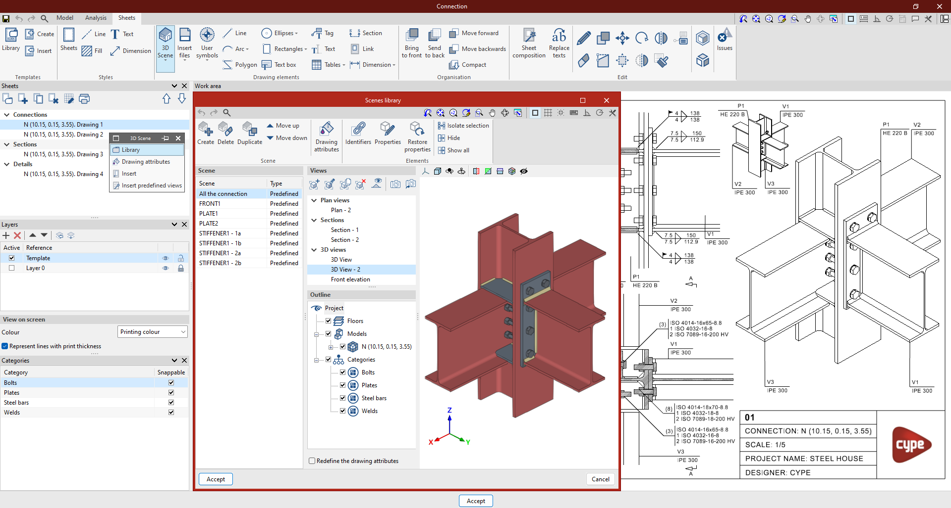
The process for generating views of the model (or part of the model) and inserting them into a previously created drawing is as follows:
- Firstly, the 3D scene "Library" is used, which makes it easier to create scenes to be incorporated into the sheets. Each scene can contain several views, and you can select which elements are displayed in each one.
- The scenes are then inserted onto the drawing using the "Insert" or "Insert predefined views" options described below.
| Note: |
|---|
| The content of the drawings is linked to the model; in other words, any scenes and views that have been defined, as well as any element labels that have been entered, will be updated automatically if changes are made to the model. If the joint is exported to the "Joint library", the drawings will also be exported and can be reused in future projects. |
Insert
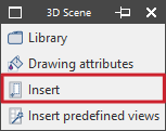
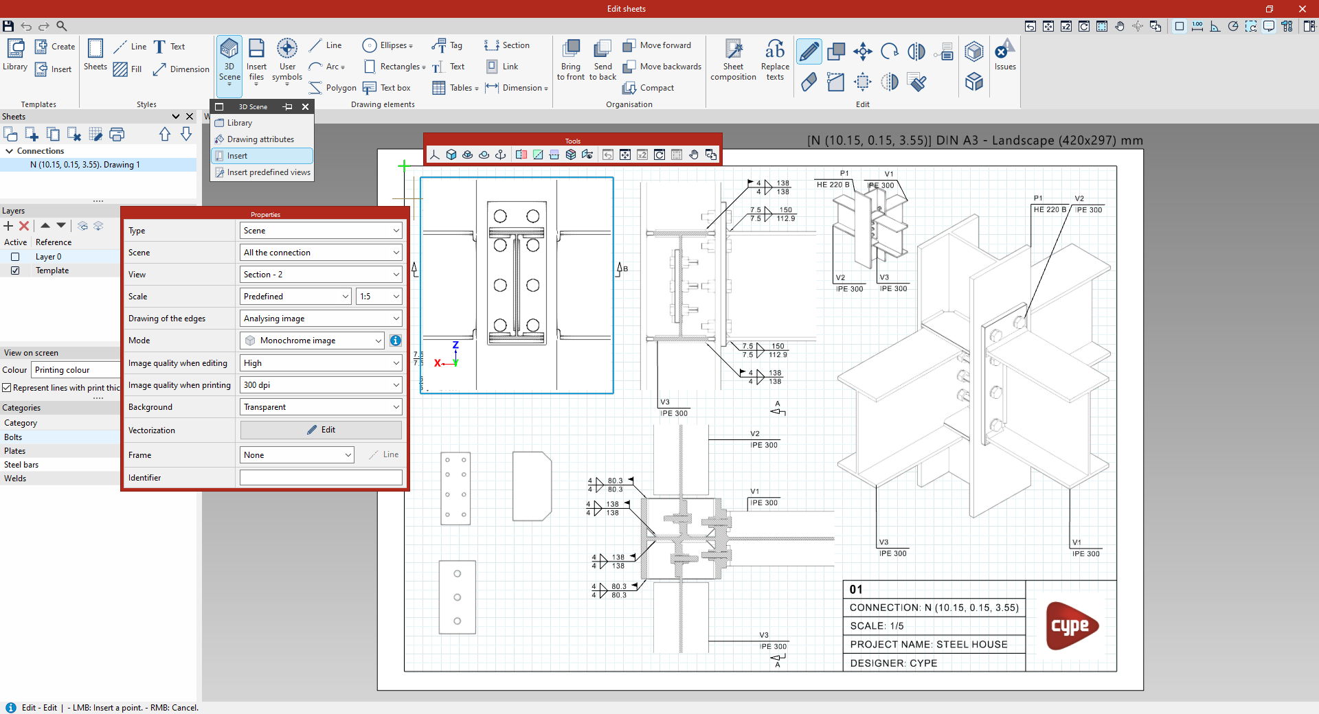
To freely insert a scene into the drawing, select the "Insert" option in the "3D Scene" menu. Then, in the workspace, draw the box where the new scene is to be inserted by selecting two corners.
Once the box has been inserted, a "Properties" panel appears. In this panel:
- Select the "Scene" and "View" you want to insert, which must have been prepared in advance in the "Scene library" (which, in turn, depends on the type of plate being edited).
- Select the "Scale", either "Depending on the zoom", a "Predefined" scale, or by entering a "Scale factor".
- Configure the "Edge drawing", either by "Analysing the image" or "Using the model’s geometry".
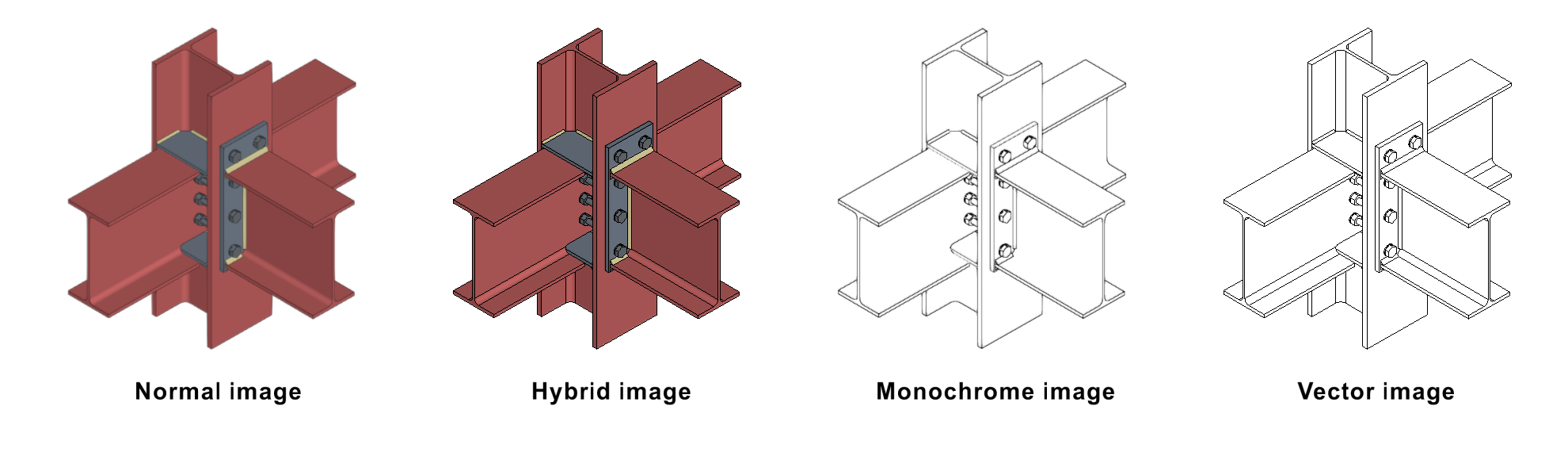
- Select the image display "Mode" from normal, hybrid, monochrome or vector.
- Select the "Image quality when editing" ("Low", "Medium" or "High") and the "Image quality when printing" (one of the various pixels per inch [ppp] values available).
- Define the "Background" ("Solid white" or "Transparent").
- Edit the "Vectorisation" options.
- Add a "Frame" if desired.
- Specify an "Identifier" for the scene.
- Edit the "Tag generation" settings.
At the same time, a "Tools" panel appears, where you can change the projection on the fly, rotate the view of the inserted scene or cut it along section planes.
Finally, after adjusting the scene properties, click outside the box to finish inserting the scene into the sheet.
| Note: |
|---|
| If necessary, you can use the "Object reference" option on the top toolbar, as well as the "Grid" on the sheet, to position the scene frame accurately on the sheet. |
Insert predefined views
The "Insert predefined views" option, within the "3D Scene" menu, can be used to automatically generate and insert predefined views of the model or part of the model into the drawings.
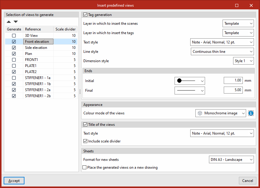
In the pop-up window that appears when you click on this option, you can configure the generation and insertion of views:
- On the left, you can "Select the views to generate" by ticking the "Generate" box for the desired views, which are identified by their "Reference", and where you can also adjust the "Scale factor".
- The configuration options on the right allow you to do the following:
- Configure "Tag generation" by selecting the "Layer in which to insert the scenes", the "Layer in which to insert the tags", the "Text style", the "Line style" and the "Dimension style", as well as selecting the symbols for the "Initial" and "Final" "Ends".
- Under "Appearance", select the "Colour mode of the views" (normal, hybrid, monochrome or vector).
- Optionally, you can add the "View title" by selecting its "Text style" and, if desired, "Include scale divider".
- In "Sheets", select the "Format for new sheets" if you need to create new drawings to insert the views, and, if desired, you can "Insert the generated views into a new sheet" rather than into the one currently visible by selecting the last option.
When you confirm, the program will generate the specified views and automatically place them on the project sheet(s).