

3D scene library
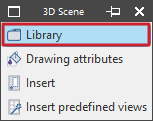
The "Library" option, within the "3D scenes" menu (found in the "Drawing elements" section of the top toolbar) in the sheet editor, lets you manage the scene library in CYPE Connect.

The 3D scene library can prepare, create and configure views of the model or parts of it for later insertion into drawings, such as plans, elevations, sections and perspectives.
Scene library interface
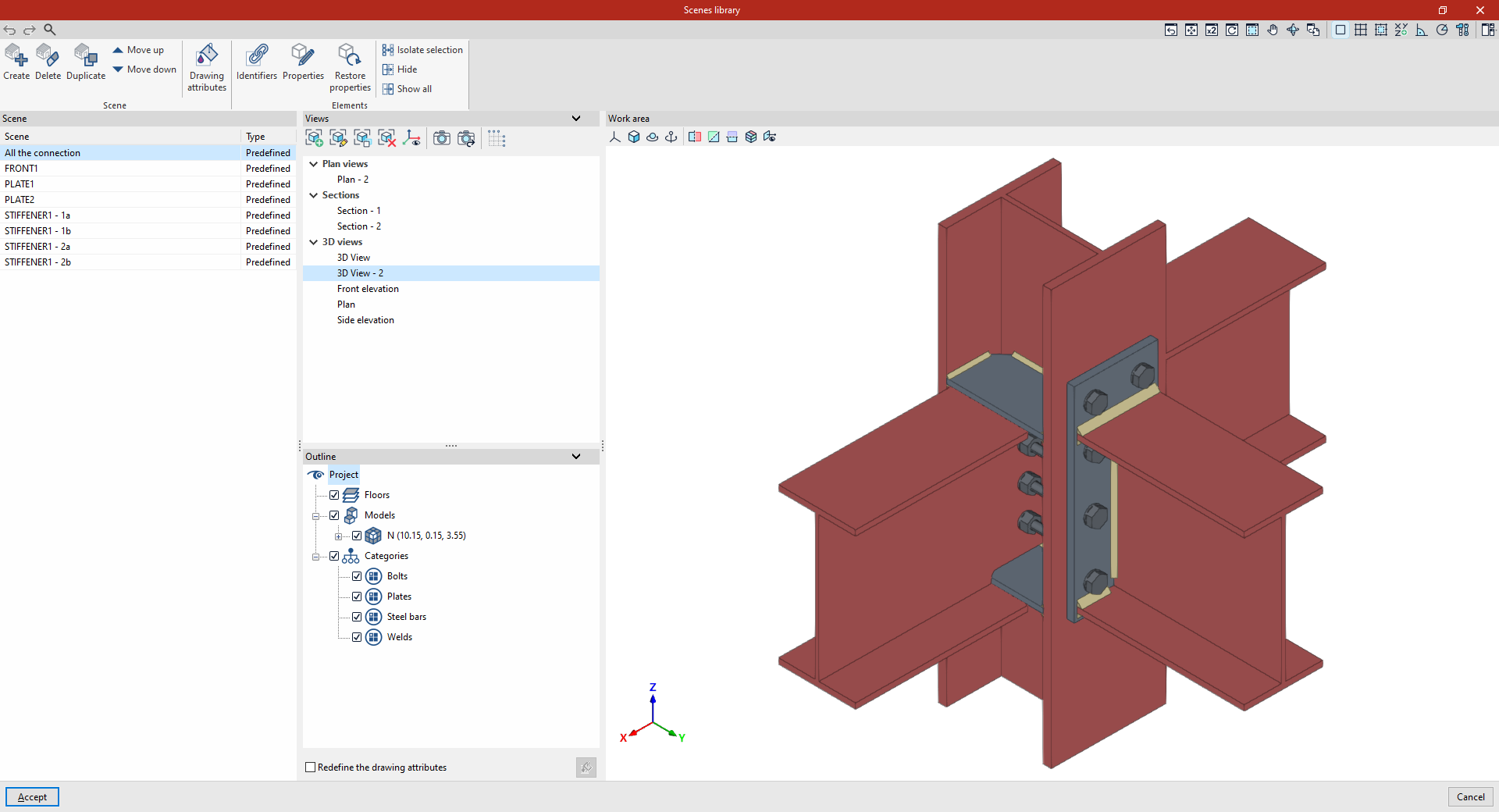
The "Scene library" window that appears when you click on this option displays an interface with the following sections:
"Scene" section
On the left-hand side, in the "Scenes" section, a list of the scenes available in the library is displayed. Each scene represents the model, or part of the model, configured in a specific way, which may contain different views and display properties.
The "Scene" column displays an editable reference that lets you identify it, while the "Type" column indicates whether the scene is "Predefined" or "User-defined".
For example, in the scene library for a connection, the program may display one scene for the entire connection, and several additional scenes for each of its components.
"Views" section
In the top centre, in the "Views" section, there is a set of tools common to other CYPE programs that let you create and manage different views, including floor plans, elevations, sections and perspectives.
"Outline" section
At the bottom centre, the "Outline" section lets you show or hide the desired elements that make up the scene, including the option to do so by "Floors", "Models" or "Categories" of elements.
Work area
On the right-hand side is a 3D view of the model elements shown in the scene for the selected view.
Here, you can change the projection, rotate the model or cut it along different section planes to adjust the display for each view.
| Note: |
|---|
| The elements shown in each scene depend on the type of sheet being edited When editing sheets using the "Parts", "Assemblies", "Connections" or "Model views" (or in the "Sheets" tab of the assembly editor), only those scenes in the scene library that represent the corresponding part, assembly or assembly, or the model of the complete structure, respectively, will be available. When editing sheets using the “Composition” option, all types of scenes will be available, as indicated in the “Model” column in the scene library. In this case, it is also possible to add a “BIM Model” scene, which allows all elements imported from the BIMserver.center project to be displayed. |
Options in the "Scenes" group
In the top toolbar, the "Scenes" group includes the following options:

Create / Delete / Duplicate / Move up / Move down
These options let you manage the list of scenes available in the "Scenes" section. You can create different scenes, delete them, duplicate them or reorder them. Only user-defined scenes can be deleted.
Drawing attributes
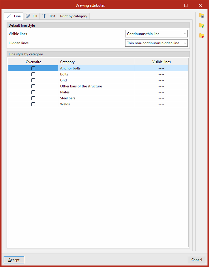
The “Drawing attributes” option lets you configure aspects such as "Line", "Fill" and "Text" styles for all scenes in the library, using the various tabs available in the window that opens when you click on this option. You can apply common default styles to all elements or apply specific styles by element category, selecting them from those available in the style libraries.
Furthermore, on the "Print by category" tab, you can select the categories of elements to be included in the final printout. Elements belonging to unchecked categories will still be displayed on the on-screen sheets, but will not be printed.
| Note: |
|---|
| You can also configure the "Drawing attributes" via the relevant option in the "3D scenes" menu, within the main interface of the sheet editor. |
These drawing attributes will apply to all scenes. If you wish to configure the drawing attributes for a specific selected scene, you can do so by ticking the "Redefine the drawing attributes" box, available under the "Outline" section at the bottom of the central panel.
Options in the "Elements" group
In the top toolbar, the "Elements" group offers the following options:

- Identifiers
Freely assign identifying text to each of the selected elements in the scene. - Properties
Edit the specific drawing properties of each of the selected elements in the scene. These include the option to "Redefine the drawing mode" of the element – whether "Normal", "Transparent" or "Wireframe" – as well as to "Redefine the section hatch" by applying a specific hatch style from those available. - Restore
Restore the drawing properties of all elements in the scene.
The following options can only be used in user-defined scenes:
- Isolate selection
Hide all elements in the scene except for the selected element, which is displayed in isolation. - Hide
Hide the selected items. - Show all
Display all the elements in the scene again, should any of the previous options have been used.
Once you have finished configuring the scenes, click "Accept".
