Creating a new job, linking to a project and importing data
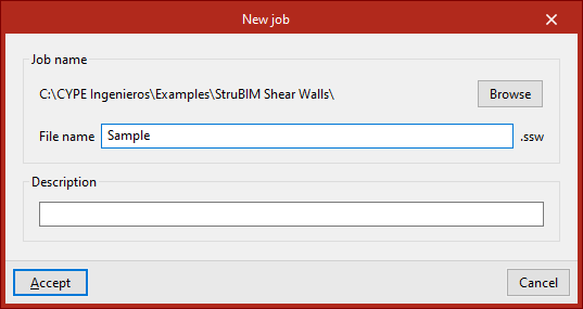
When you launch the app and click on “New”, you are given the option to create a “New project”. After entering the “File name” and “Description”, the project can then be added to an existing project on BIMserver.center.
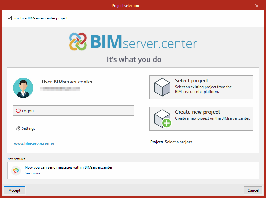
This is done in the "Project selection" window, which offers the following options:
- On the left-hand side, you can log in using a BIMserver.center account.
- On the right, use the "Select project" option to choose an existing project. You also have the option to "Create a new project". In that case, the project you create will be visible on BIMserver.center from that point onwards.
- You have the option to start the project without linking it to the BIMserver.center platform. To do this, simply uncheck the box labelled "Link to a BIMserver.center project", which is located in the top-left corner.
Once the new project has been created, you will be taken to the program’s main interface. At any point during the project, you can share or import project files via the "BIMserver.center" panel, located in the top right-hand corner of the main interface.
Importing BIM models
When creating a new project, if you have selected a project hosted on the BIMserver.center platform via "Select project", the "Import BIM models" window will appear, displaying the files contained in that project in IFC format.
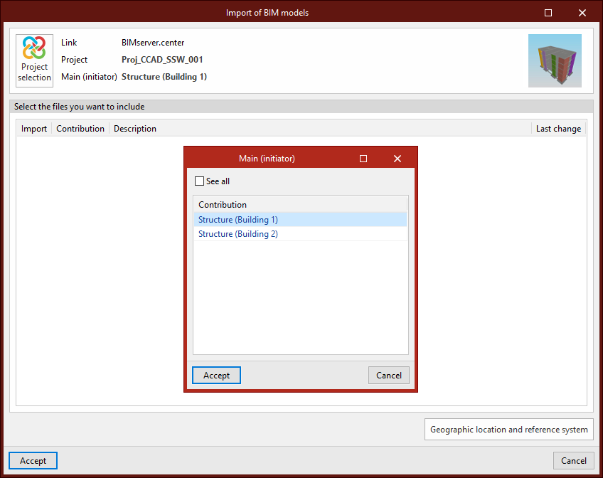
If there are several .ifc files in the project, a pop-up window will appear in which you must select the "Main (initiator)" file from the available options. This is the file from which the information will be extracted in the data import wizard.
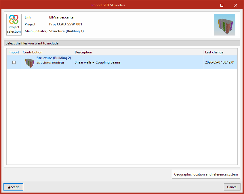
In addition, in the "Select the files you want to include" section, the app allows you to include auxiliary files for viewing within the program. To do this, tick the "Import" box and confirm.
Shear wall and coupling beam import wizard
Shear walls and coupling beams can be imported from data read from the BIM model within StruBIM Shear Walls.
To do this, after selecting the main or starter file to be imported, the program opens a "BIM Model Import" wizard comprising the following steps:
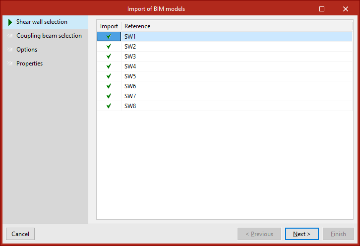
- In the first stage, you select the shear walls to be imported. Each one appears in the list with its "Reference" and can be "Imported" by ticking the box in the left-hand column.
| Note: |
|---|
| In the original CYPECAD model, you must use the "Assign shear wall function" option on the walls you have already entered so that StruBIM Shear Walls can identify them at this stage of the wizard. You can find more information about this option via this link. |
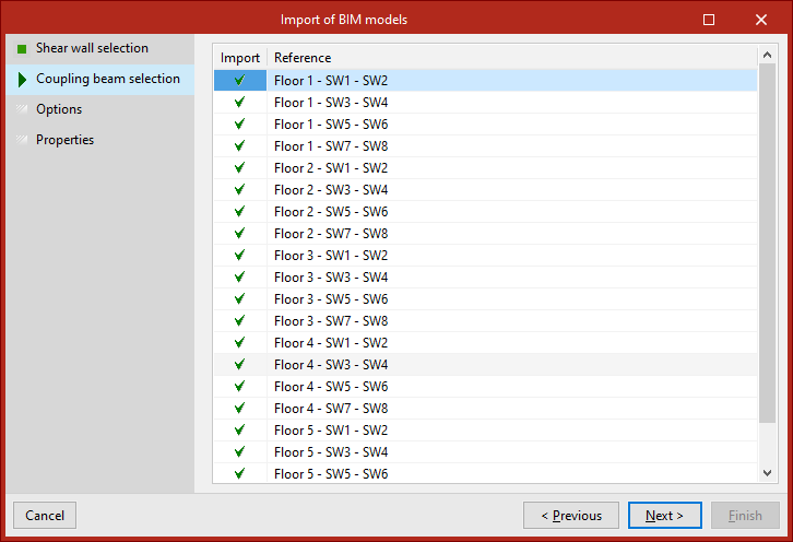
- In the second phase, you must select the "Coupling beams" you wish to import from the list provided by the program. Each beam is displayed with its “Reference” and can be “Imported” by ticking the box in the left-hand column.
| Note: |
|---|
| In the original CYPECAD model, you must use the "Automatic connection beams" and/or "Define connection beams" options on the beams you have already entered so that StruBIM Shear Walls can identify them at this stage of the wizard. You can find more information about these options via this link. |
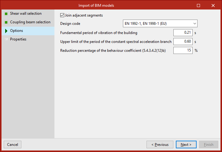
- The settings for various "Options" required for the calculation are reviewed below. You can "Join adjacent segments" by ticking the relevant box. In addition, the program identifies and allows you to select the "Design code" to be complied with from the drop-down menu and, where applicable, review and configure the parameters relating to the selected standard.
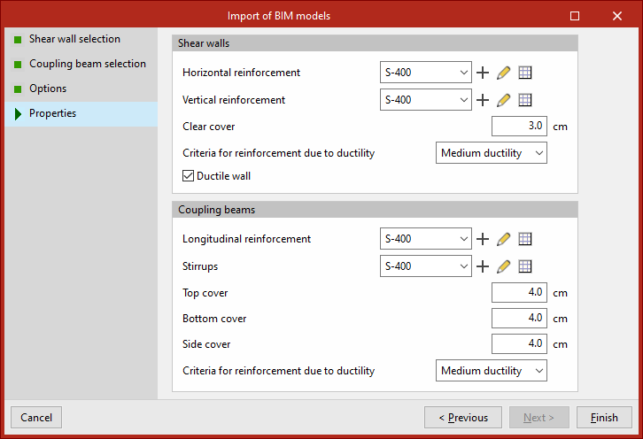
- In the final stage, the "Properties" of the imported elements are imported and checked. This includes:
- In the "Shear walls", the steel for the "Horizontal reinforcement" and the "Vertical reinforcement" is identified, as is the "Clear cover", and, depending on the selected standard, the choice of reinforcement criteria based on ductility or seismic performance.
- In the case of "Coupling beams", the steel for the "Longitudinal reinforcement" and the "Stirrups" is also identified and can be selected; the "Top cover", "Bottom cover" and "Side cover" are defined; and, depending on the selected standard, the reinforcement criteria for ductility or seismic performance are specified.
To complete the import wizard, click "Finish".
Reinforcement layout criteria
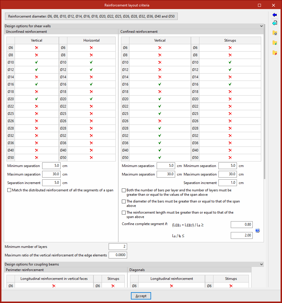
Once the import process is complete, the program will display a window allowing you to review the settings for the "Reinforcement layout criteria".
These can also be viewed later via the relevant option in the "General data" section.
Import results
Once you have clicked "Accept" in the final dialogue box and completed the import process, the program will load and open the main interface.
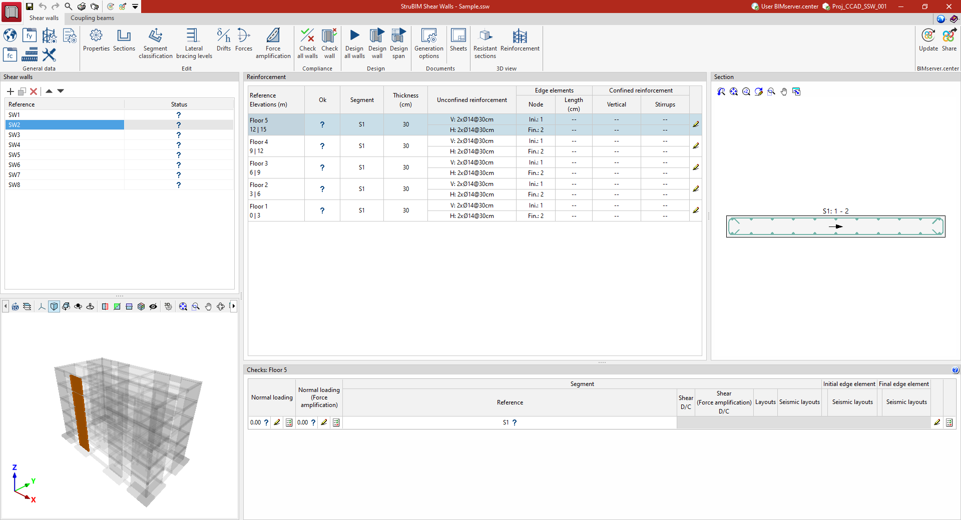
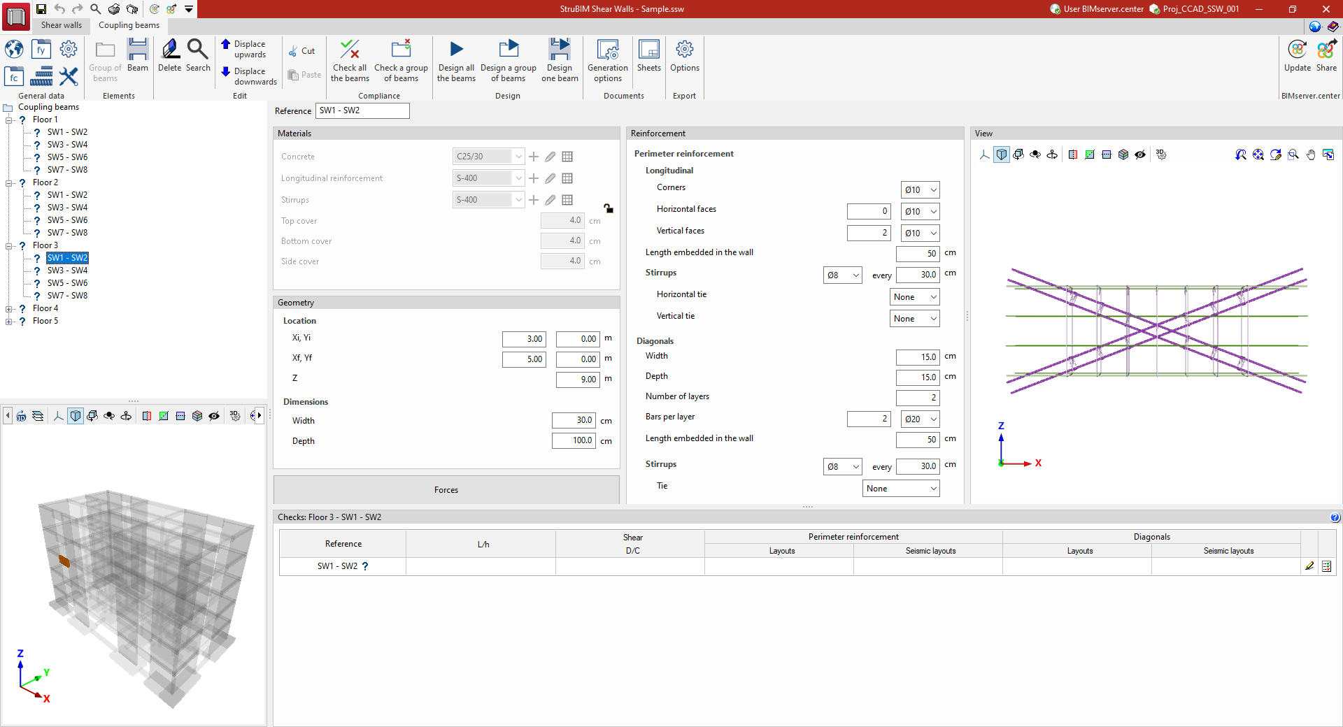
The imported shear walls and coupling beams will be displayed in the element lists on the left-hand side panel, available under the relevant tabs ("Shear walls" and "Coupling beams"). From here, you can add further elements if required.
The program will also incorporate the results of the analysis of each component, such as the forces in the shear walls and tie beams, as well as the deflections of the shear walls.
From this point onwards, users can modify the data for any of the imported walls and/or beams, as well as apply a specific reinforcement scheme and/or carry out the checks and design.