
Waffle slabs
With the "Waffle floor slab" module, CYPECAD analyses and designs waffle slabs made up of panels in which two zones are distinguished: hollow core and solid.
The discretisation of the waffle slab sections is carried out in meshes of bar-type elements whose size is one-third of the interaxis defined between ribs in the hollow core zone, and whose torsional inertia is (in both the solid and the hollow core zones) half that of the solid zone, and the torsional inertia is twice that of the bending inertia. The mesh size remains constant in both the hollow core and solid zones, adopting the average inertia indicated above in each zone.
Shear deformation is taken into account and the rigid diaphragm loadcase is maintained. The torsional stiffness of the elements is considered.
Entering waffle slabs
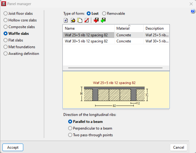
To select a waffle slab, click on the "Slabs" menu in the "Beam definition" tab and then on "Panel manager". Here, the "Enter panel" option opens a window in which "Waffle slabs" can be selected.
A new waffle slab can be chosen from a typified and editable library, imported from the "Open BIM Database" or a new one can be created.
The type of form (slab with lost or recoverable form) and the direction of the longitudinal ribs (parallel or perpendicular to a beam to be indicated, or according to the direction of two marked points) must be selected beforehand.
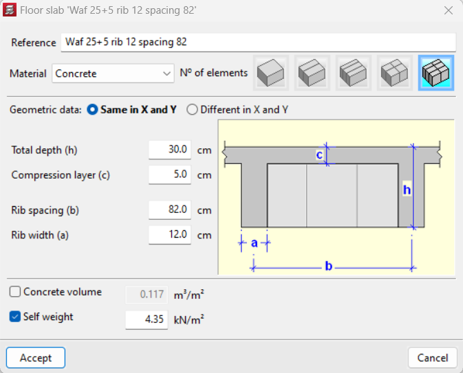
The data to be defined is as follows:
- Reference. Descriptive name.
- Material. You can choose between concrete, lightweight concrete, ceramic or polystyrene.
- Number of elements that make up the lightweight block. This is indicated by selecting the corresponding drawing according to the desired number of elements per form. The sides of the abacuses will move in increments in excess of the number of elements indicated.
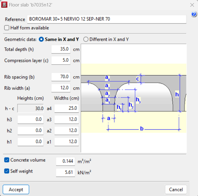
- Geometric data of the transverse section (which may be the same or different in X and Y):
- total depth;
- compression layer (thickness);
- interaxis or rib spacing;
- rib width;
- partial heights and widths (only for floors with removable form).
- Concrete volume. The program analyses the concrete volume based on the dimensions entered.
- Self weight. This is the self-weight of the floor slab (of the hollow-core area only) and must be computed as the sum of the weight of the volume of concrete and the weight of the form.
After entering this data, users can change the insertion point of the mesh or the direction of the ribs in the slab by clicking on "Change insertion point" and "Change layout" respectively.
Data for waffle slab type panel
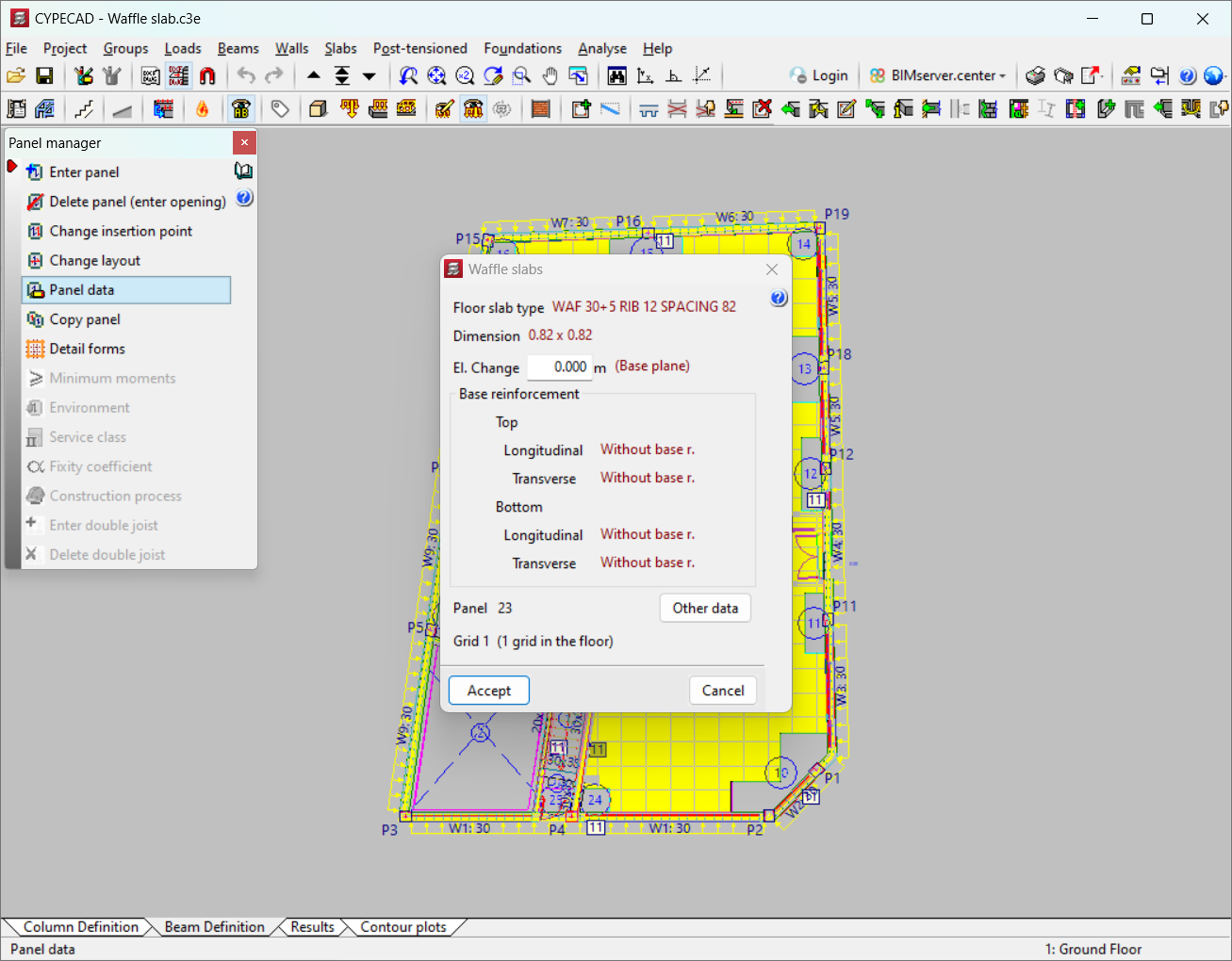
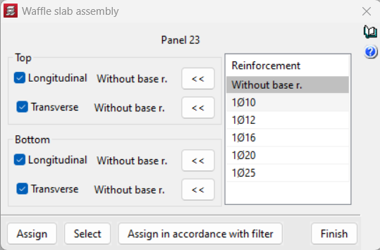
Under "Panel data" the slab type and dimension are displayed. Furthermore, users can set the elevation differences between panels, check the longitudinal or transverse, or top or bottom base reinforcement, view the panel and mesh number, and other data.
By default, waffle slab panels are displayed without base reinforcement ("Without base r."). To assign a base reinforcement in both the top and bottom direction, it must be defined in the "Slabs" menu of the "Beam definition" tab, under "Assign 'Base reinforcement / Welded mesh'".
A base reinforcement can be defined or not, distinguishing the solid zone from the hollow core zone:
- Base reinforcement in the solid zone (drop panels)
By default, a base reinforcement consisting of 2 rounds (according to tables) is considered, which extends from one edge of the drop panel to the other, and is distributed between the axes of the ribs that collaborates whenever it is considered. This is also called "drop panel assembly reinforcement". - Base reinforcement in ribs
By default, this is not considered. Therefore, it must be chosen and determined in each direction. There are reinforcement tables that allow their definition, as well as their possible combination in the additional reinforcements to be placed in the ribs.

Detailing base reinforcement in drawings
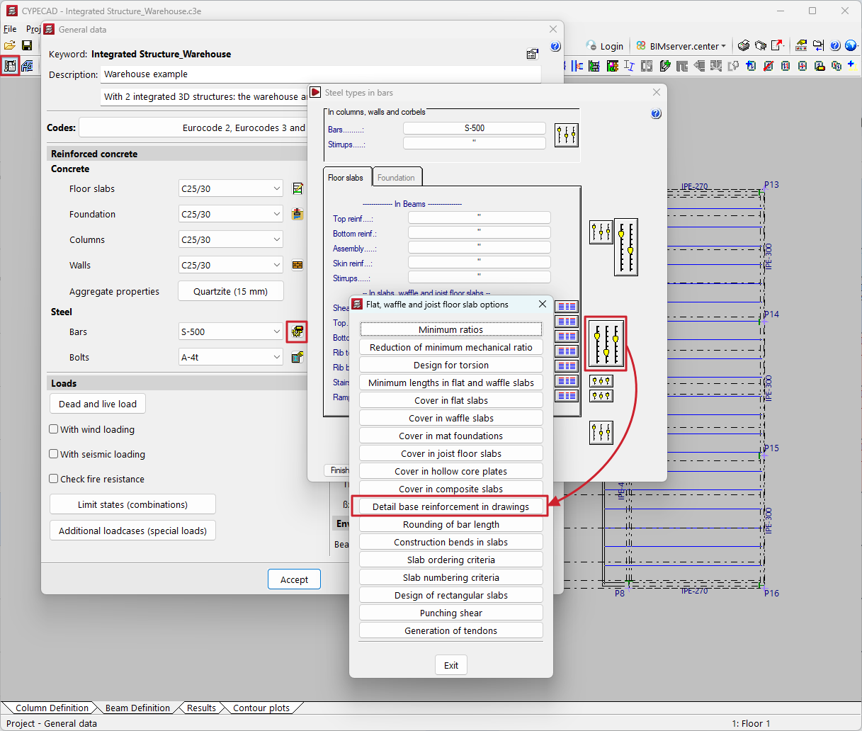
To consider the base reinforcement in detail, remember to activate the design option "Detail base reinforcement in drawings", which can be found in the "Project" menu, by accessing "General data", and the "By position" icon, and then "Options" for the reinforcement of slabs and waffle and joist floor slabs.
If this option is not activated, the base reinforcement will not be visible and only the reinforcement will be shown. Therefore, this reinforcement will not be measured in reports or quantities table drawings. When launching drawings it is essential to ensure that the presence and consideration of the base reinforcement is recorded. Drawings should be reviewed and details added to indicate overlap lengths and areas where it can be implemented.
If the option is activated, the base reinforcement shall be displayed as an additional reinforcement and may be edited and modified.
Additional longitudinal reinforcement
The same criteria for flat slabs are applied, except that the reinforcement is concentrated on the ribs. The envelopes of the elements adjacent to the rib must first be grouped together for the reinforcement to be concentrated at the position of the rib.
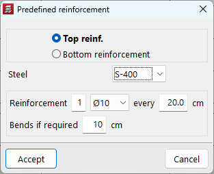
Predefined reinforcement
With this option, users can enter additional reinforcement for waffle slabs in any direction. A different type of steel than the one selected for the main reinforcement of the slab can be entered. The program will deduct the contribution of the predetermined reinforcement from the total calculation so that each reinforcement design will be adjusted by subtracting the average mechanical capacity of the predetermined reinforcement entered. The term 'average mechanical capacity of the predetermined reinforcement' refers to the total mechanical capacity of the predetermined reinforcement entered, divided by the width of the area in which the predetermined reinforcement is placed.
Transverse reinforcement
In the drop panel or solid zone, an analysis identical to the one for flat slabs is carried out for shear and punching shear. In the ribs of the hollow core zone, the shear test is carried out on the ribs every 0.75 d. If reinforcement is necessary, vertical branches of the required diameter can be placed at the spacing and in the number drawn on the drawings and on the screen.
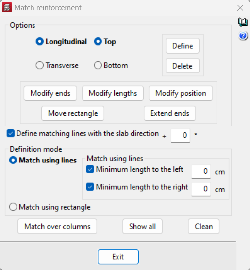
Matching reinforcement
To adjust the reinforcement of a waffle slab after the analysis, use "Match reinforcement" in the "Slabs" menu. In the options box, select the reinforcement (longitudinal or transverse, top or bottom) and choose the matching mode (line or rectangle). In the case of line levelling, minimum lengths can be set on both sides. Other options include entering lines with a specific angle or with any angle, modifying ends, lengths and positions, or the ability to automatically match negatives over columns, among others.
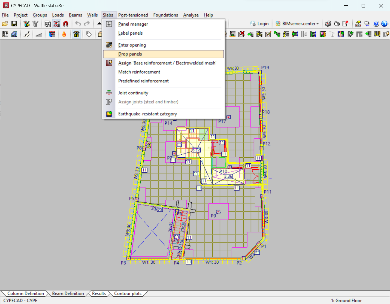
Entering solid zones or drop panels
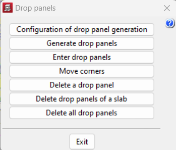
The solid zones or drop panels can be generated automatically, on columns or in any area of the slab, adopting the same edge as the hollow core panel in which they are located. To do this, the "Drop panels" option must be selected from the "Slabs" menu, in the "Beam definition" tab. Furthermore, a bottom drop can be applied to the slab to give it a greater depth.
When drop panels are generated automatically, the dimensions in each direction are adjusted to 1/6 of the distance of the column corresponding to the nearest column, according to a viewing angle of 40º. If no other column can be "seen" (e.g. edge columns), this takes the same value as the one obtained in the opposite sense of the same direction. The limits of the drop panels are at least 2.5 times the edge, and no more than 5 times the edge. There is an option, called "Configuration of drop panel generation", to automatically configure the drop panels, and the parameters can be varied.
If the drop panels are generated manually, solid zones can be entered, always adjusted per the number of parts of the lightweight element. This should not be used to simulate beams. In this case, beams should always be defined at the free edges.
Openings
The slabs without any floor slab panels remain empty and show a question mark; therefore, the users must delete the slab, equivalent to inserting an opening, which is symbolised by two crossed dashed blue lines.
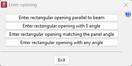
Furthermore, rectangular openings can be entered in existing waffle slab panels. The options available under "Enter opening" in the "Slabs" menu in the "Beam definition" tab are: "Enter rectangular opening parallel to beam", "Enter rectangular opening with 0 angle", "Enter rectangular opening matching the panel angle" or "Enter rectangular opening with any angle".
Results output
For waffle slabs, the program shows the following results:
- Contour plots and contour lines
Displacements, forces and ratios in cm²/m can be displayed for all the slabs in any group. - Floor plans
The table, which is always generated in the floor plan (layout), shows the base reinforcement in ribs and drop panels, even if the bars are not drawn or detailed. Optionally, the lightweight elements and form elements can be drawn. - Reports
The reports of "Displacements in nodes of flat and waffle slabs" or "Forces in nodes of flat and waffle slabs" are particularly noteworthy.
User license
For CYPECAD to be able to analyse and design waffle slabs, the user license must include the "Waffle floor slabs" module in addition to CYPECAD.
Other features
To access other features offered by the program, there are several modules which can be found on the "CYPECAD modules" page.