
Introduction
CYPE Connect is a tool for the modelling, analysis and code checking of connections in steel and timber structures using the finite element method. The program includes the OpenSees© analysis engine, developed at the University of California, Berkeley, to carry out complete analyses. In addition to the designs and checks, CYPE Connect has a tool for generating sheets with the detailing drawings of the connections.

Workflows supported by the program
CYPE Connect offers different workflow options as it is an Open BIM tool and is connected to the BIMserver.center platform.
- Modelling, analysis and graphical information of individual connections are all done completely within the program itself
- Importing a steel structure previously analysed in CYPE 3D
- Importing a steel structure previously analysed in CYPECAD
- Importing structural steel models in IFC format via IFC Uploader
- Importing structures developed with other tools via StruBIM Uploader
- Importing structures from an XML file generated by ETABS®

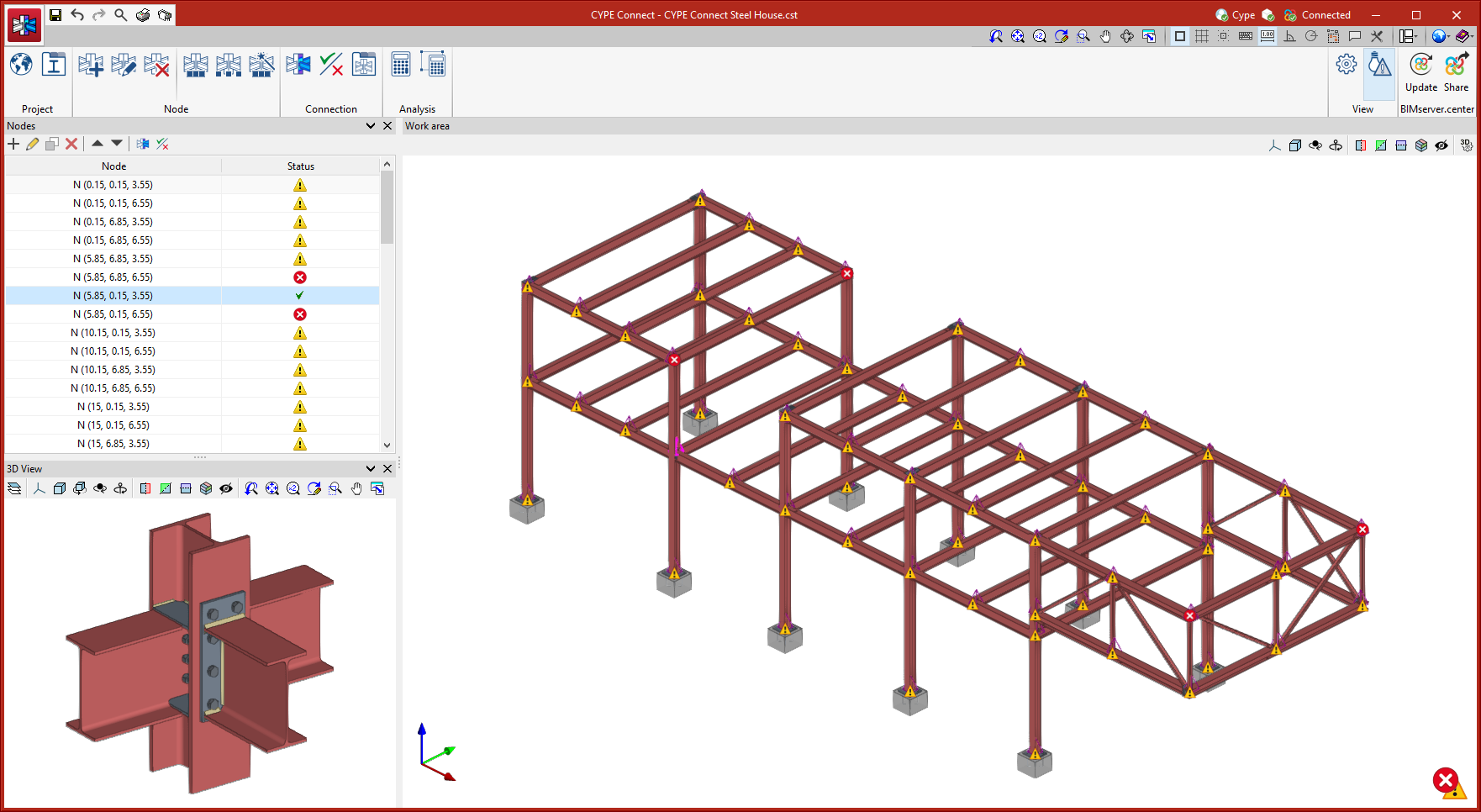
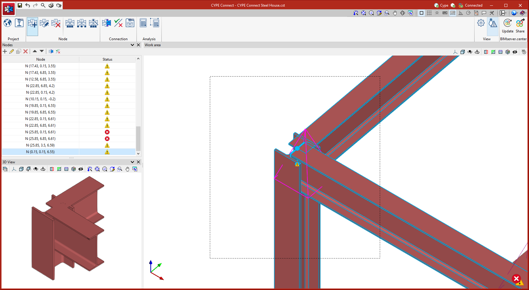
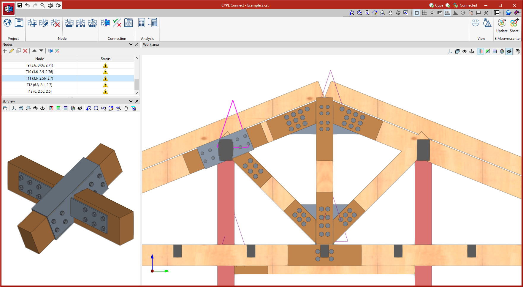
Working environment
The CYPE Connect working environment follows the style of other CYPE modelling tools.
The top toolbar contains the main features for creating project libraries, creating and managing the nodes to be analysed, and editing and analysing the connections.
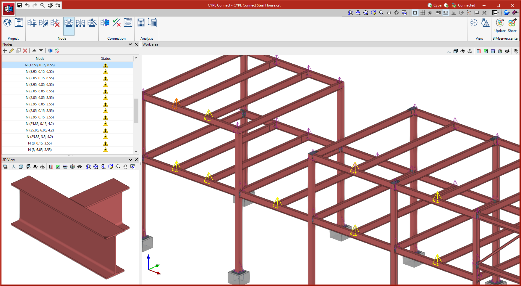
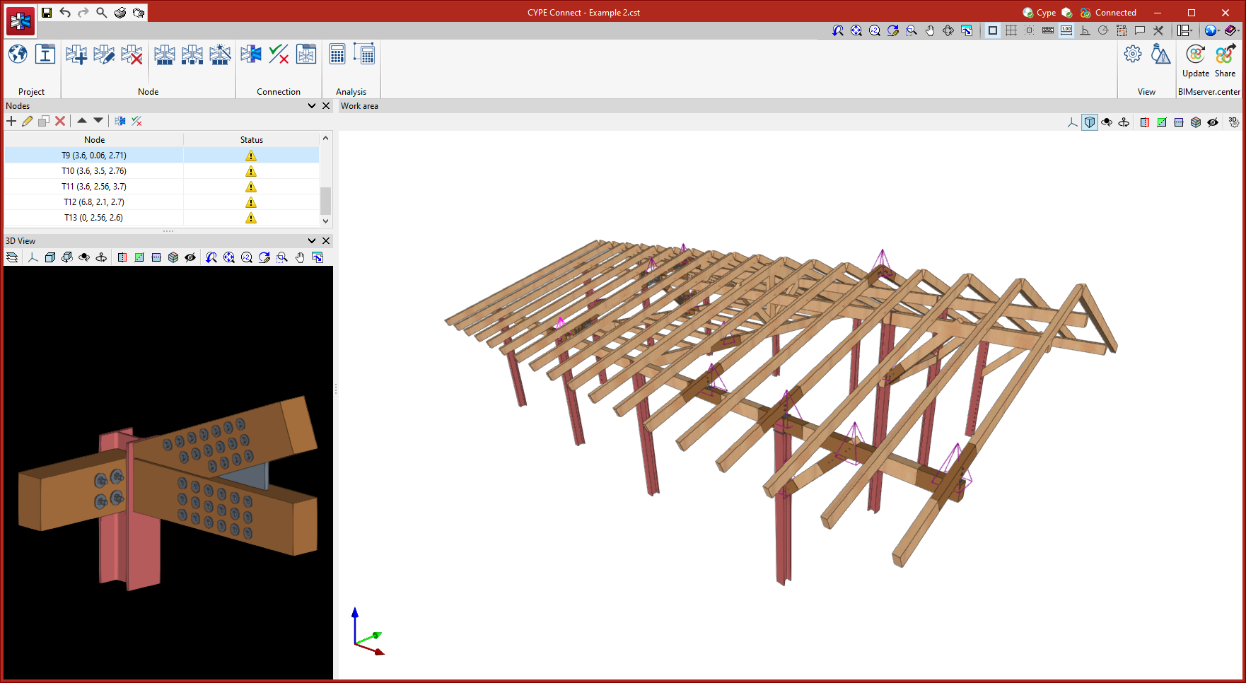
The model viewing area is located on the right-hand side of the main interface and allows users to select the analysed connections, as well as to view all the elements of the project in 3D.
The list of existing nodes in the project is located on the left-hand side. Any element selected in the 3D model is highlighted in the list and vice versa. Also, the program notifies users of the status of each connection by means of warning symbols.
A detailed view of the node selected in the list or in the 3D model is displayed in the bottom left corner.
Getting started
CYPE Connect allows users to work both by creating new nodes and entering forces and combinations manually, and by importing structural BIM models, which the program will interpret in order to generate nodes automatically. CYPE Connect can import the nodes and forces of steel and timber structures developed in CYPECAD and CYPE 3D.
Defining the project characteristics
In the main toolbar, in the "Project" group, the following project data can be defined:

Selecting the code used in the connection analysis
As an alternative to the detailing of the connections that can be performed in StruBIM Steel, the program also offers users the possibility to analyse the connections using CYPE Connect, which works together with StruBIM Steel, as long as both programs are included in the license. In this case, the selection of the design codes for the different project materials is carried out from the “Codes” window.
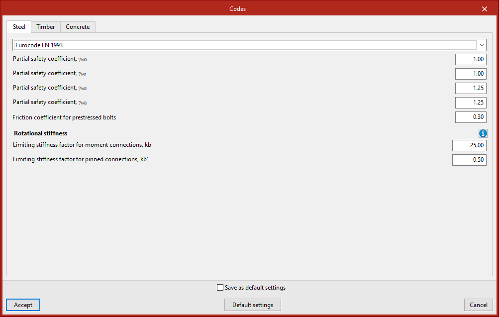
Codes available in the program:
Steel:
- ABNT NBR 8800:2008
- AISC 360-16 (LRFD)
- BS 5950-1:2000
- Código Estructural
- EAE 2011
- Eurocode EN 1993
- IS 800:2007
Timber:
- Eurocode EN 1995
Concrete:
- Eurocode EN 1992
- ACI 318M-19
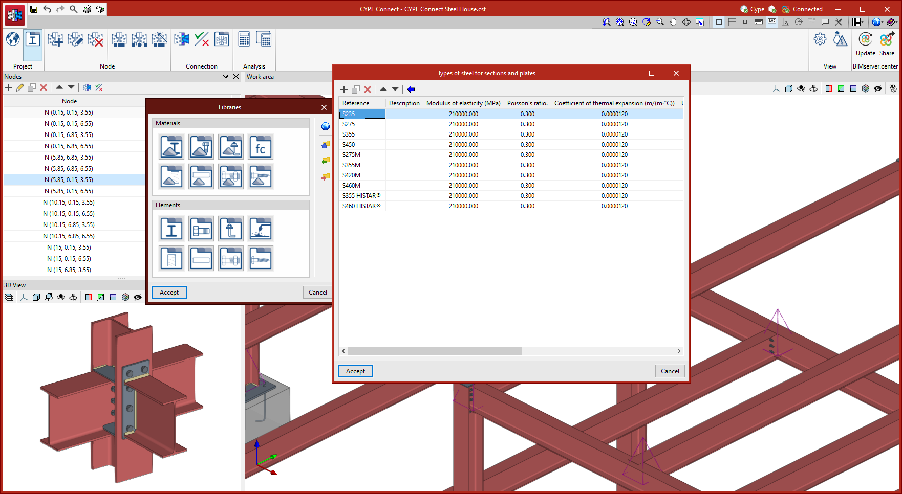
Materials library
CYPE Connect allows the following characteristics of the materials used in the project to be saved in its material libraries:
Types of steel for sections and plates
The steel required for manufacturing the sections and sheets of the project can be saved in the program’s library by entering the reference, description, modulus of elasticity, Poisson’s ratio, coefficient of thermal expansion, unit weight, yield strength and fracture limit. There is also the option of detailing the resistance criteria depending on the thickness of the material.
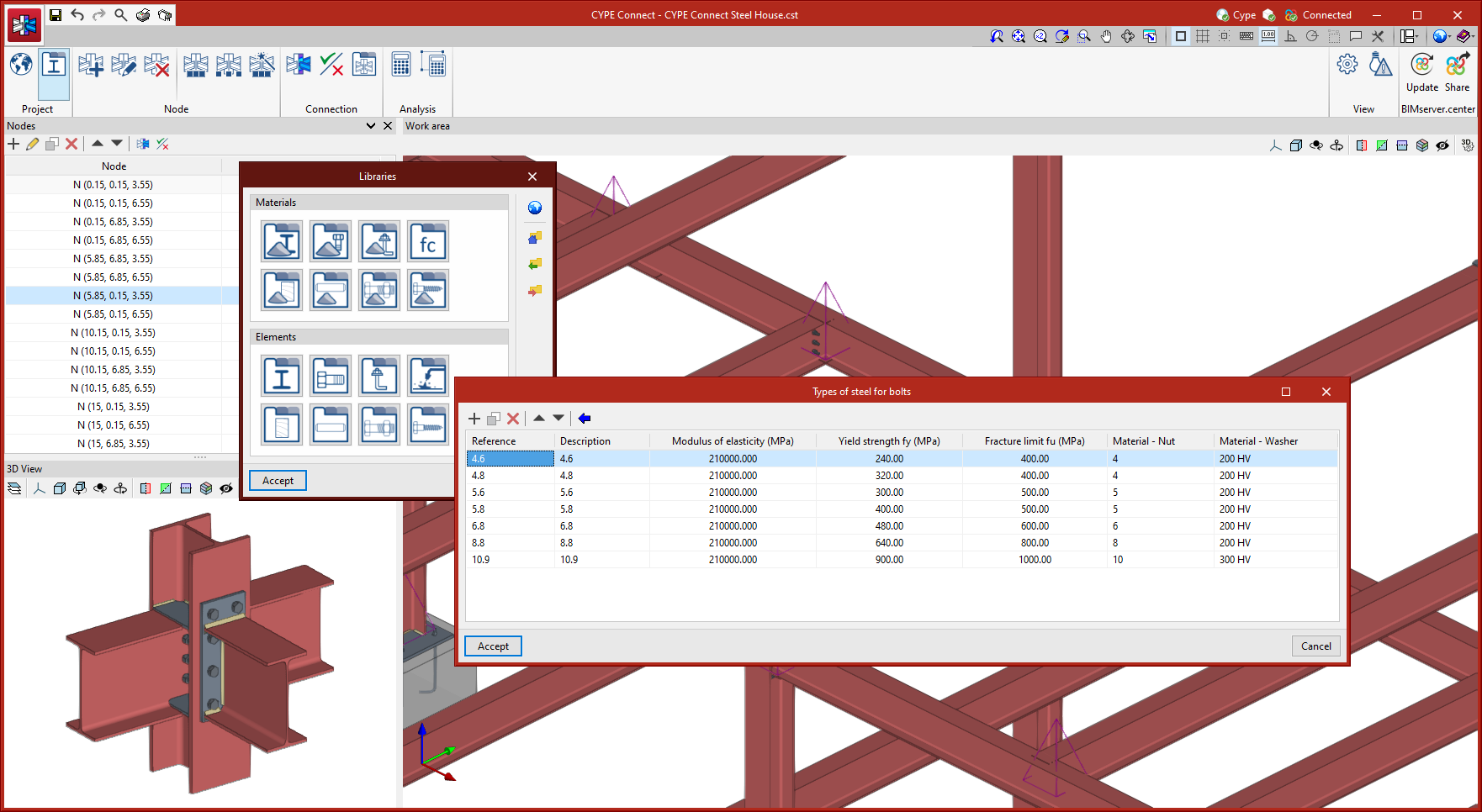
Types of steel for bolts
The steel required for characterising the bolts in the project can be saved in the program’s library by entering the reference, description, modulus of elasticity, yield strength and fracture limit. There is also the option of detailing the materials of the nuts and washers.
Types of steel for anchors
The steel required for characterising the anchors of the project can be saved in the program’s library after entering the reference, description, modulus of elasticity, yield strength and fracture limit. There is also the option of detailing the materials of the nuts and washers.
Types of concrete
The types of concrete used can also be saved in the program library. To do this, the reference, description, compressive strength, compressive strain in the concrete at maximum stress and the ultimate compressive strain of the concrete must be entered.
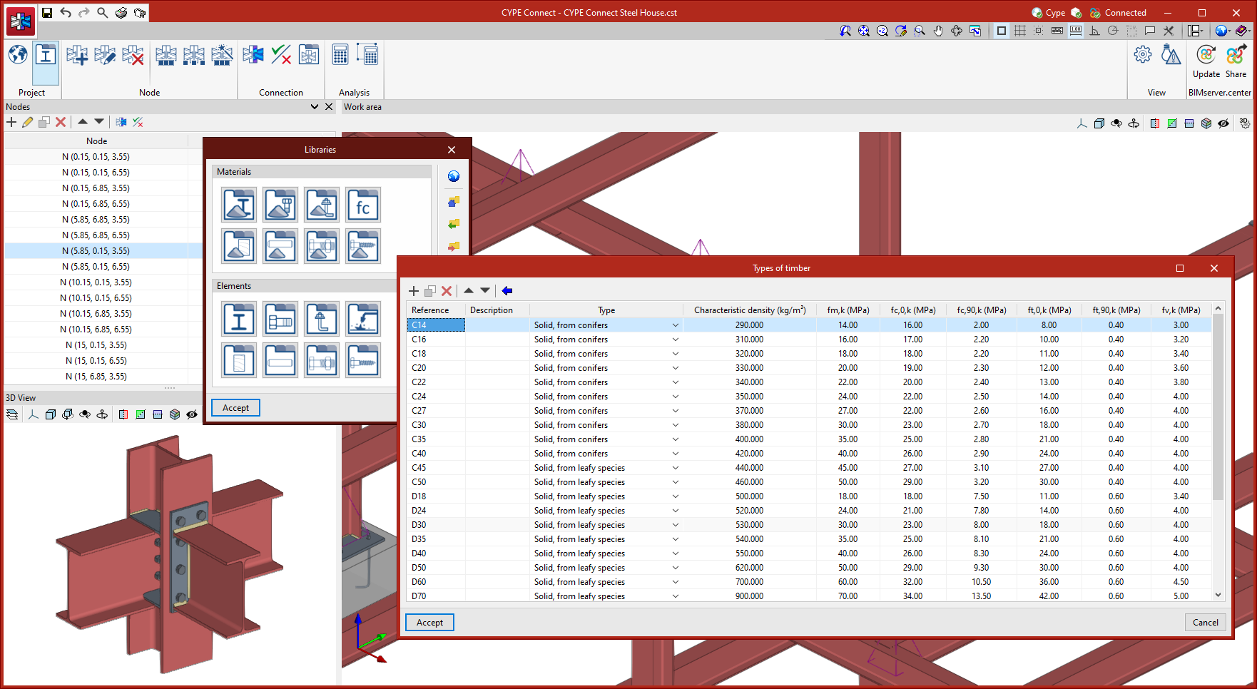
Types of timber
The timber required to manufacture structural timber elements can be saved in the program's library by entering its reference, description, type, characteristic density and other data related to its mechanical resistance. The program includes a wizard that makes it easy to enter the most common types of timber for different uses.
Materials for dowels
The materials required for characterising the dowels can be saved in the program's library by entering their reference, description, modulus of elasticity, yield strength and fracture limit. The program includes a wizard that makes it easy to enter the most common types of timber for different uses.
Materials for bolts
The materials required for characterising the bolts can be saved in the program’s library by entering their reference, description, modulus of elasticity, yield strength and fracture limit. The program includes a wizard that makes it easy to enter the most common types of timber for different uses.
Materials for screws
The materials required for characterising the screws can be saved in the program’s library by entering their reference, description, modulus of elasticity, yield strength and fracture limit. The program includes a wizard that makes it easy to enter the most common types of timber for different uses.
Elements library
CYPE Connect allows the characteristics of the elements to be saved in the following libraries:
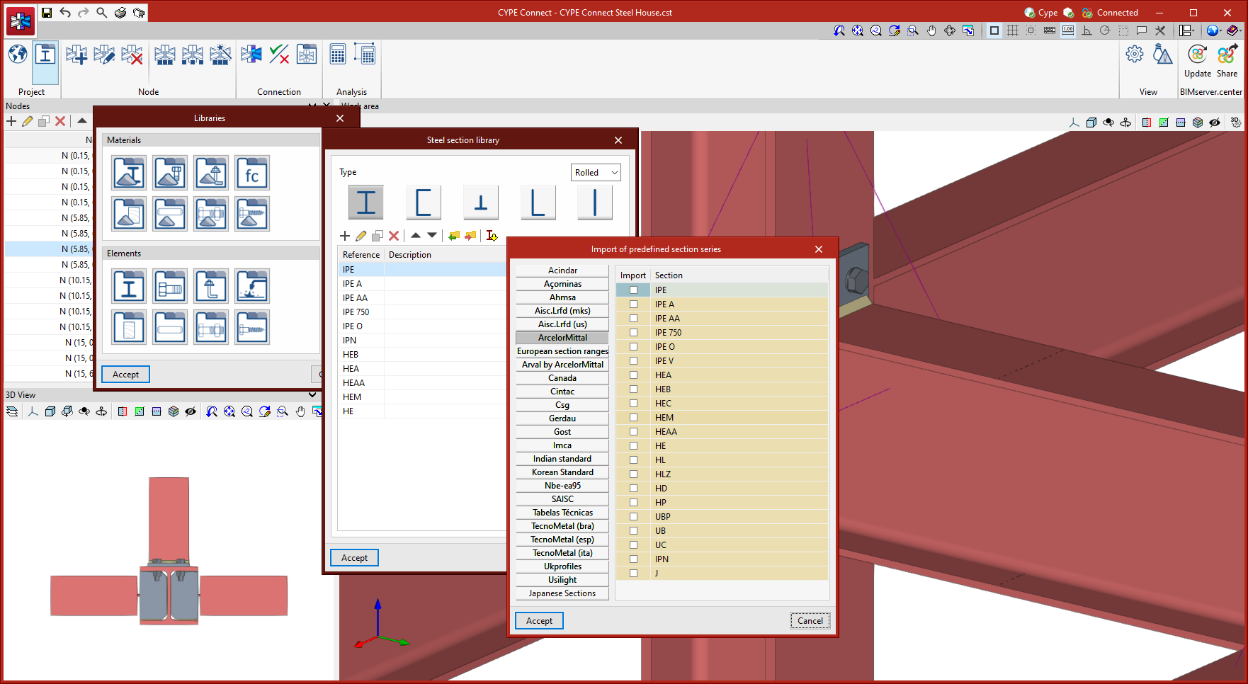
Section library
The CYPE Connect sections library allows users to enter rolled, reinforced, cold-formed and tubular steel sections of various types. As well as manually entering sections, CYPE Connect allows the import of pre-defined section series according to standards, with codes and manufacturers from a wide range of countries.
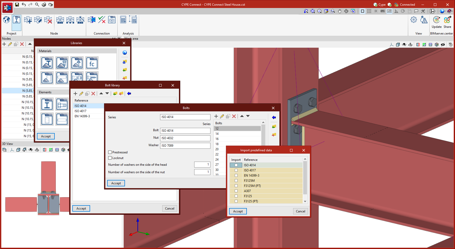
Bolt library
The CYPE Connect bolt library allows series of bolts to be stored depending on different geometrical characteristics. Each series can also be characterised by entering a reference, whether or not there is a locknut, whether or not the bolt is pre-stressed, and the number of washers. As well as manual bolt entry, CYPE Connect has an extensive library of bolts including standards from a wide range of countries.
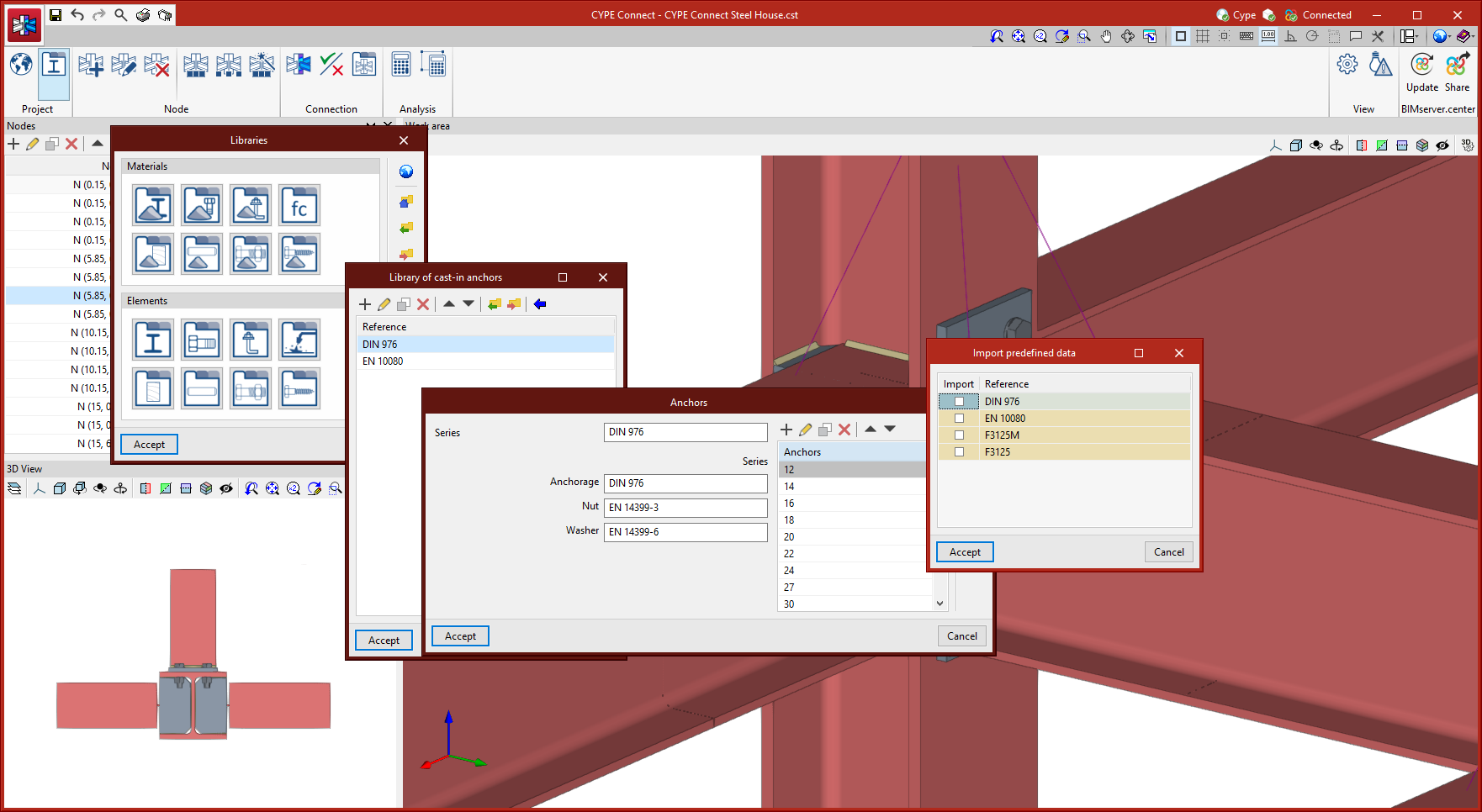
Library of cast-in anchors
The CYPE Connect library of cast-in anchors allows series of anchors to be registered, considering different geometrical characteristics. As well as the manual entry of anchors, CYPE Connect allows predefined data to be imported for different types of cast-in anchors.
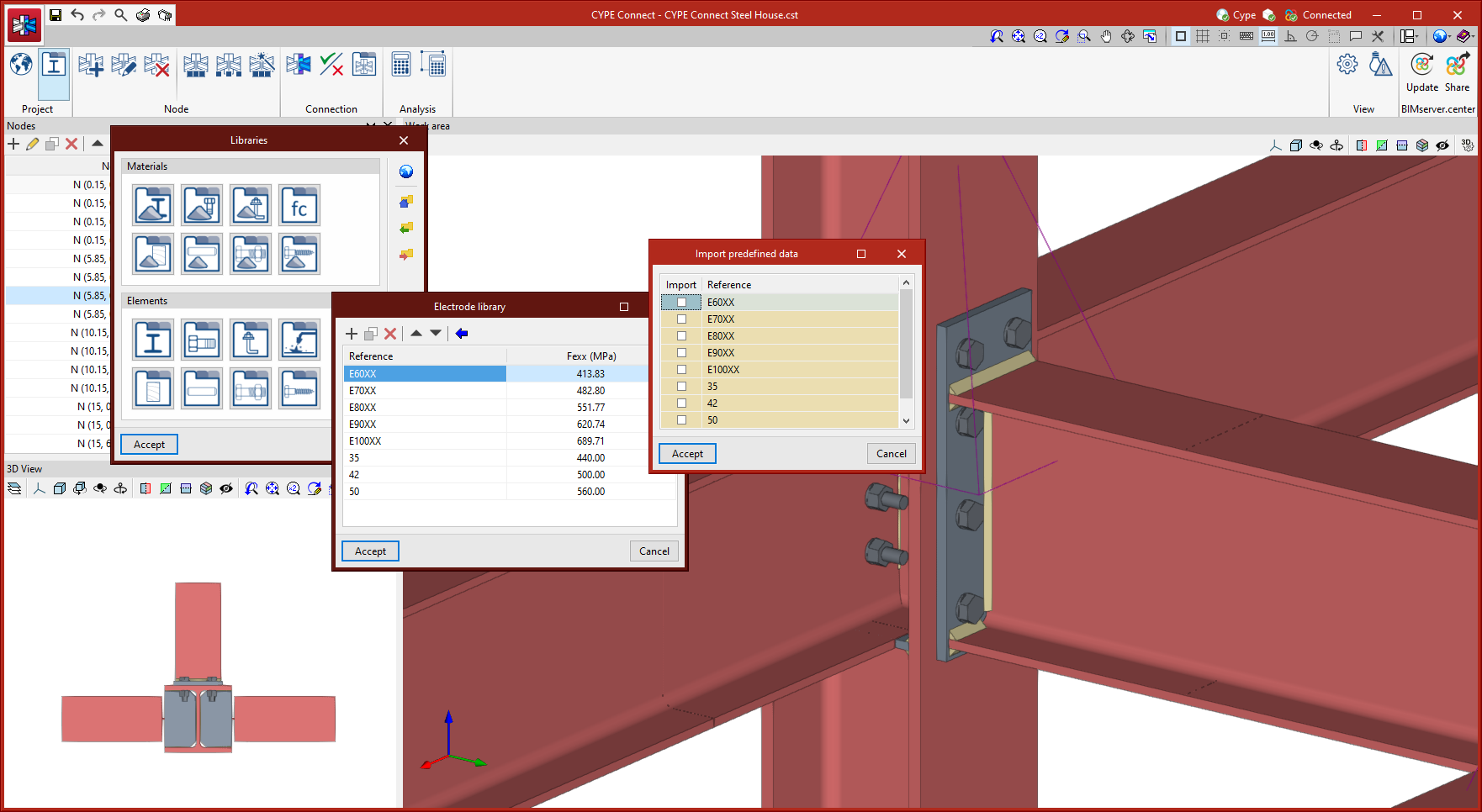
Electrode library
The CYPE Connect electrode library allows electrodes to be saved by entering a reference and resistance. As well as the manual entry of electrodes, CYPE Connect allows predefined data to be imported for different types of electrodes.
Timber sections library
The CYPE Connect timber section library allows timber sections to be saved by entering their reference and geometric characteristics. As well as the manual entry of timber sections, CYPE Connect allows predefined data to be imported for different types of timber sections.

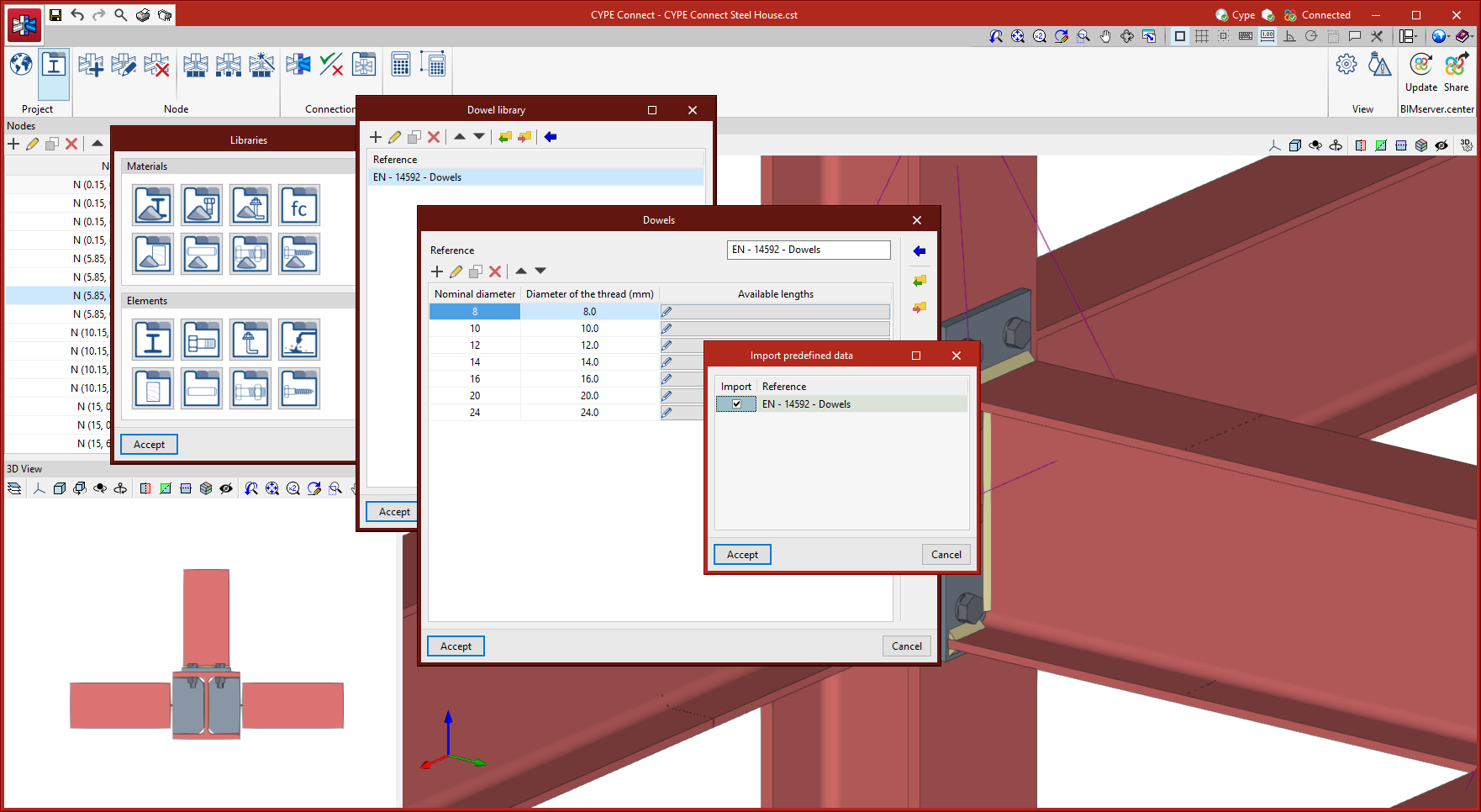
Dowel library
The CYPE Connect dowel library allows dowels to be saved by entering their reference and geometric characteristics. As well as the manual entry of dowels, CYPE Connect allows predefined data to be imported for different types of dowels.
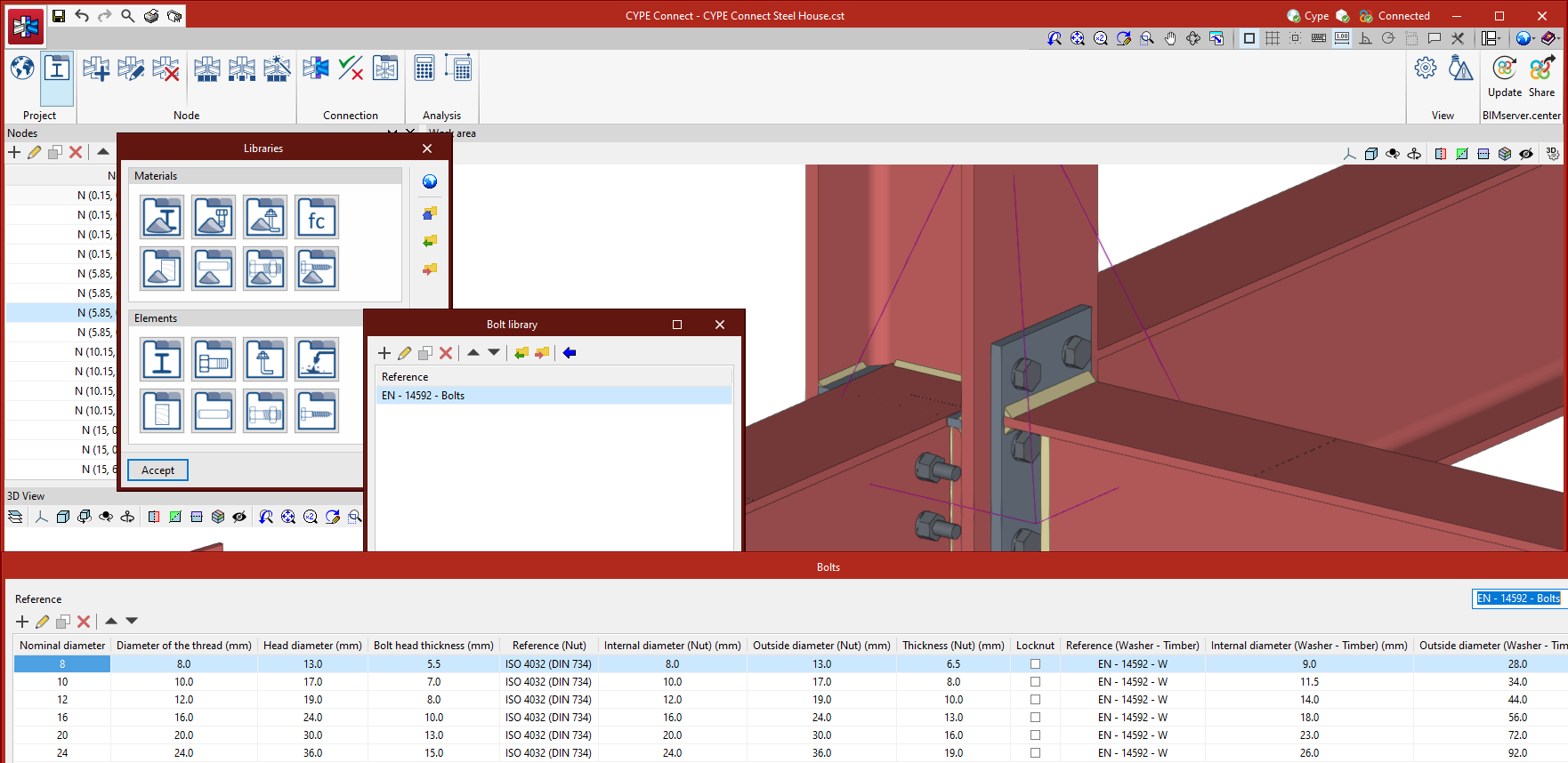
Bolt library
The CYPE Connect bolt library allows bolts to be saved by entering their reference and geometric characteristics. As well as the manual entry of bolts, CYPE Connect allows predefined data to be imported for different types of bolts.
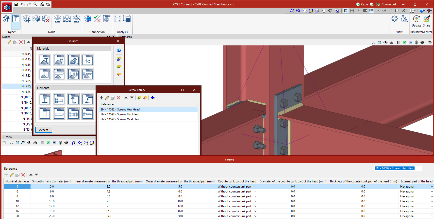
Screw library
The CYPE Connect screw library allows screws to be saved by entering their reference and geometric characteristics. As well as the manual entry of screws, CYPE Connect allows predefined data to be imported for different types of screws.
Creating and editing structure nodes
The "Node" group in the top toolbar has different tools for creating, editing and managing the nodes of the structure. Once they have been defined manually or imported from the BIM model, the connection of the structural elements converging at each node can be modelled.
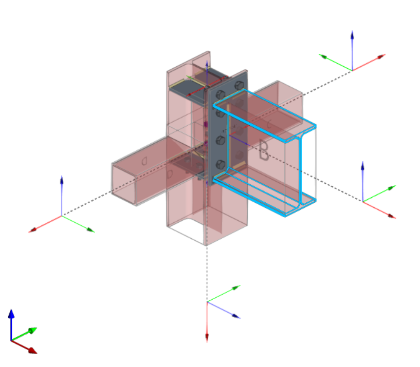
New node
The "New" option allows a node to be created by selecting two or more bars with a common point. The bars can be selected one by one or by using the crossing method. The selected bars are highlighted in blue. When the operation has been confirmed, a new node is added to the list of nodes on the left-hand side of the interface, and a magenta pyramid appears on the node, representing it.
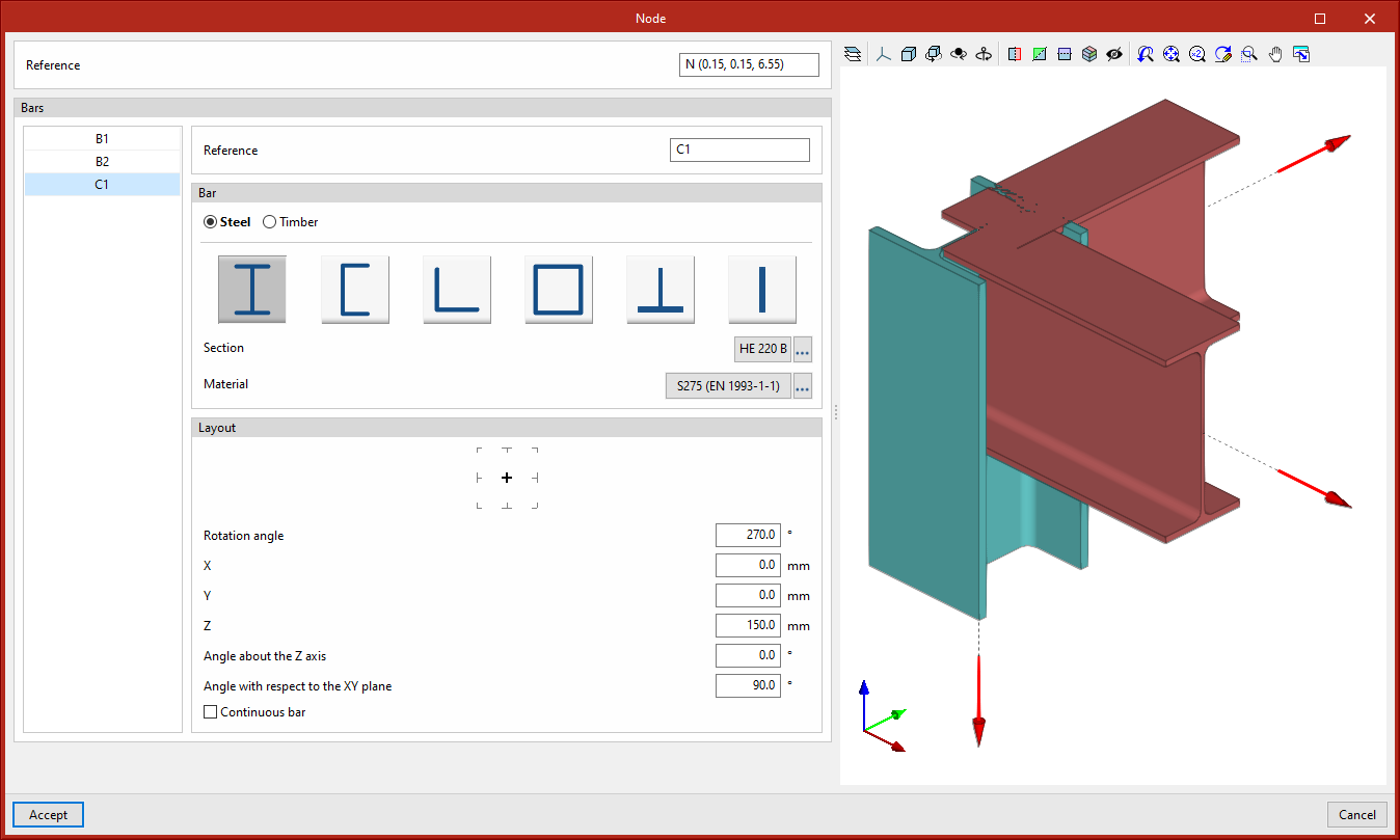
Edit node
By selecting the "Edit" option and clicking on the pyramid symbol representing the previously created nodes, a window opens where different parameters related to the node can be edited.
Here you can edit the node reference, add or remove bars, modify the bar sections and their arrangement, and view the node in 3D.
Delete node
Using the "Delete" tool, by clicking on the "pyramid" symbol on each of the previously created nodes, the node will be deleted from the model and from the list of nodes.
The same connection shall be assigned to a group of nodes. The connection assigned to a node group will obtain the bar forces of all nodes in that group from the BIM project. The combination filter carried out from "Generate from the BIM model" is based on the sum of the combinations of all the nodes.
The options for managing these groups are the following:
Group
Allows matching nodes to be grouped together. The connection applied to a group of nodes will obtain the bar forces of all the nodes in the group from the project.
Ungroup
Allows previously grouped nodes to be ungrouped.
Group automatically
Automatically groups matching nodes. The connection applied to a group of nodes will obtain the bar forces for all nodes in the group from the project.
Modelling, analysis and graphical information of connections
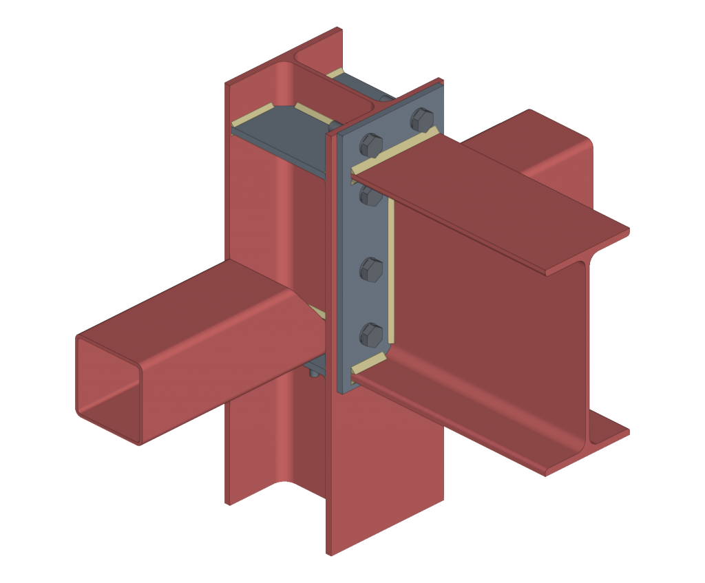
Types of connections
CYPE Connect offers the possibility to analyse connections between structural elements made of steel, timber or elements of both materials in the same connection. The analysis also includes the possibility of modelling anchor elements fixed to concrete columns.

Both StruBIM Steel and CYPE Connect include a specific tool for modelling connections between structural steel elements. Both programs can access this tool via the "Connections" option.
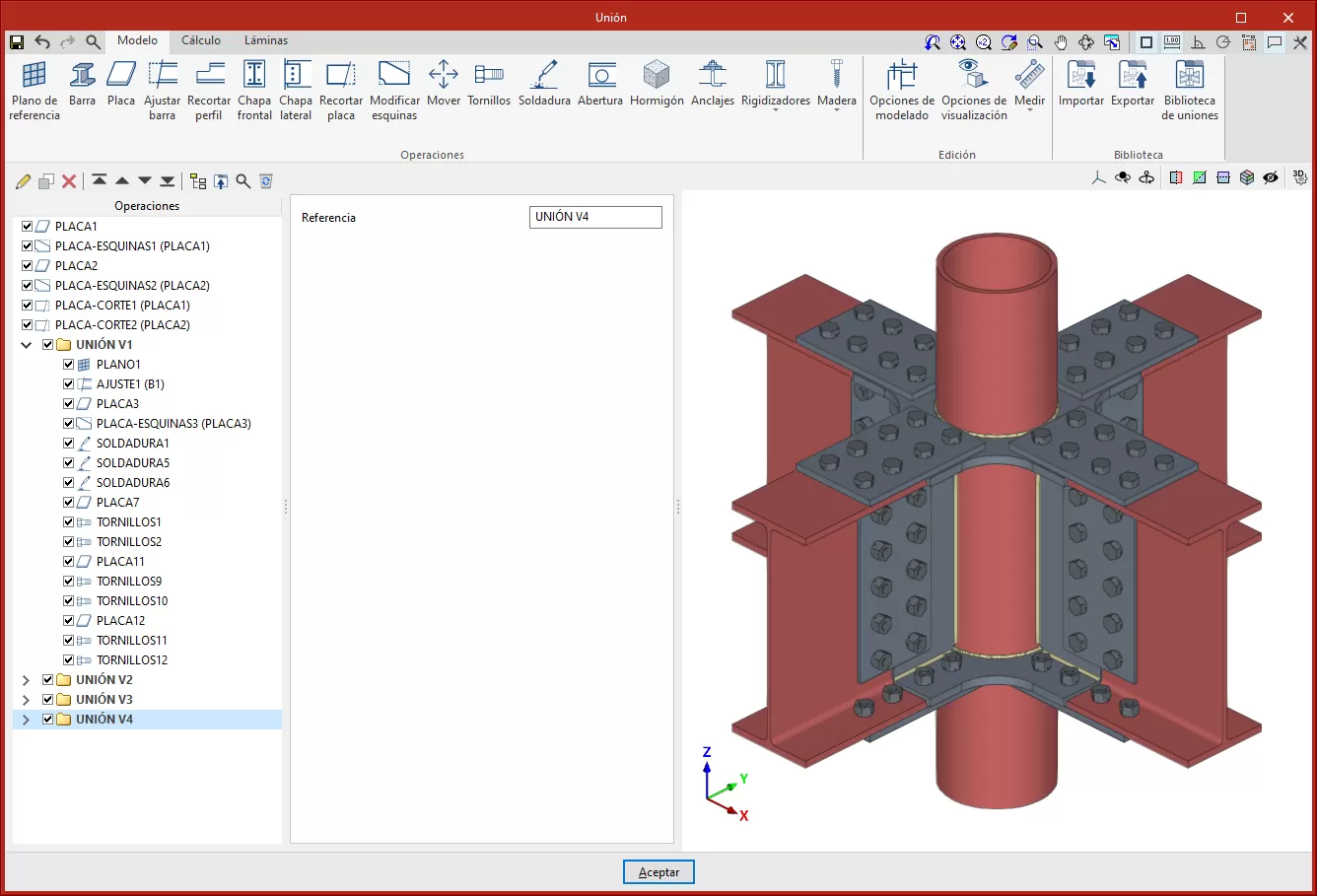
The modelling and connection analysis panel has three tabs at the top: "Model", "Analysis" and "Sheets".
Modelling connections
Within the "Model" tab, users can enter a list of operations that are used sequentially to define the elements and geometry of the connection.
The entry order and the nomenclature used to identify each operation directly affect the way in which the connections are generated. During the modelling process, the program displays warnings about possible incompatibilities between modelled elements.
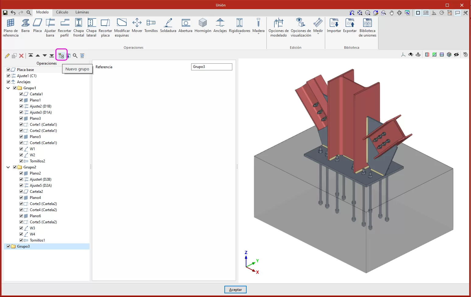
The connection editor is used to organise the list of operations by including groups of operations with an icon to identify each operation in the list.
It also has an option bar that includes several features.
- The "New group" option adds a new empty operation group. When a group is selected, new operations are added within this group. To insert or move an existing operation into or out of a group, use the tools to move up or down, depending on the position. Operations can also be dragged and dropped into or out of a group. This feature allows moves operations or groups of operations to another position, allowing an operation to be moved directly to the desired position without having to go through the intermediate positions one by one. Groups of operations can be expanded or collapsed, to either display or hide the operations they contain.
- A group of operations can be activated or deactivated by ticking the box on the left-hand side of the name for each group, which will affect all the operations included in the group.
- "Move up" moves the selected operation or group to the top of the list.
- "Move down" moves the selected operation or group to the end of the list.
- "Search" is used to search for operations by text.
- "Delete all the elements from the list" deletes all operations and groups of operations from the list.
- "Copy", with a group selected, is used to copy the group with all its operations.
- "Delete" is used to delete the group and all the operations it contains, or to delete the group and keep the operations ungrouped.
- "Export selected transactions to library", if you have a group selected, exports all the transactions contained in that group.
The main toolbar in this group allows the following operations to be carried out:
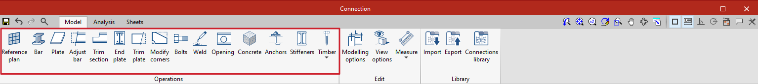
| Reference plan | Reference plans are used to make cuts in sections and plates, to make extension or reduction adjustments to these plans, or as a reference when adding plates. | |
 | Bar | This tool allows additional bars to be added to the connection in order to create drops, support elements, reinforcement for corbels, etc. |
 | Plate | This tool allows rectangular and polygonal plates to be generated. Polygonal plates can be defined from coordinates (tables can be copied and pasted directly from spreadsheets). |
 | Adjust bar | This operation allows a bar to be lengthened or shortened by fitting it to another bar, a reference plane or a plate. It also allows welds to be generated after this fitting. |
 | Trim section | This operation makes it possible to create a trim on the selected section according to the "x" and "y" magnitudes entered. The type of trim can also be defined: straight, with a chord radius or with drill. |
 | End plate | This operation allows one section to be joined to another by means of an end plate. Welds can be entered from the section to the plate and bolts can be entered between the plate and the section. |
| Lateral plate | Allows sections to be joined together by means of a plate welded to one section and bolted to the other. | |
 | Trim plate | This operation allows a plate to be trimmed from another element. The trim can be carried out from the face of a bar, from a previously defined reference plan or from another plate. |
| Modify corners | Allows users to define bevel, chamfer, notch, round and arc cuts at the corners of the plates. | |
| Move | Allows bars or plates to be moved using another element as a reference. | |
 | Bolts | This operation is used to enter bolts into the connection. Two elements to be bolted must be selected. If more than two are selected, the end elements of the connection must be indicated. |
 | Weld | This operation is used to enter welds between two elements. Both "Fillet", "Butt" and "Lap" welds can be created. |
 | Opening | This operation allows openings to be created in sections or plates. The openings can be circular or polygonal. |
 | Concrete | This operation allows concrete elements to be entered into the connection. Where necessary, anchors will be applied on top of them. |
 | Anchors | This operation is used after a plate has been entered and allows anchors to be added to the plate. Anchors are entered in the same way as the bolts. |
 | Stiffeners | This operation is used to enter the stiffeners via a wizard where their material, geometry, position and welds are defined. |
 | Timber | This operation is used to insert fasteners used in timber bars. It allows users to enter dowels, bolts and screws for timber. This feature is only available in CYPE Connect. |
As well as the operations already mentioned, the program offers other additional tools to make the modelling of the connection easier:
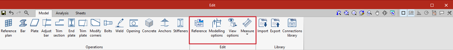
Reference: can be automatic or user-defined. The automatic reference is made up with the prefix defined in the sheet generation options. This feature is only available in StruBIM Steel.
Modelling options: allows users to edit the representation lengths and the analysis of the sections. For sections with curved segments, the program can analyse an optimal number of sides when discretising these segments or they can be chosen manually.
View options: allow the view of the elements to be configured so that they are displayed opaque or transparent, with or without reference axes, with or without labels and with or without the volume of the envelope.
Measure: allows measurements to be taken by selecting the elements of the connection.
Analysis and code checking of connections
Once the connection has been modelled, the analysis and checking can be carried out. The "Analysis" tab has the following options for this purpose:
Generate from the BIM model
This option will be available when the job has been created from a BIM model with forces. The load cases and loads of the sections involved in the connection can be generated.
To do this, the load combinations to be read can be filtered. Not all load combinations have significant values, so it may be advisable to filter the number of combinations to be imported. By default, a filter is shown for each of the 6 forces. The combinations in which the force exceeds the maximum value by a certain percentage, both positive and negative, will be read for each force. Furthermore, a minimum value can be set to determine whether the combinations should be read.

With this option, loads can also be imported for the rotational stiffness analysis. In addition to the loads, the elastic lengths of the bars of the structural model are also imported; these lengths are necessary for the correct classification of the connection. There are five options for importing load cases according to forces:
- Maximum moments, with simultaneous forces
Imports the load cases with the largest moments "My" or "Mz", with a positive or negative sign, in addition to the other simultaneous forces. - Maximum moments, without the other forces
Only imports the "My" and "Mz" values from load cases with maximum moments. - Maximum moments by plane, with simultaneous forces
Imports load cases with maximum moments and their simultaneous forces per plane i.e. creates load cases with forces per plane (XY and XZ). - All
Imports all load cases. - None
No load cases are imported.
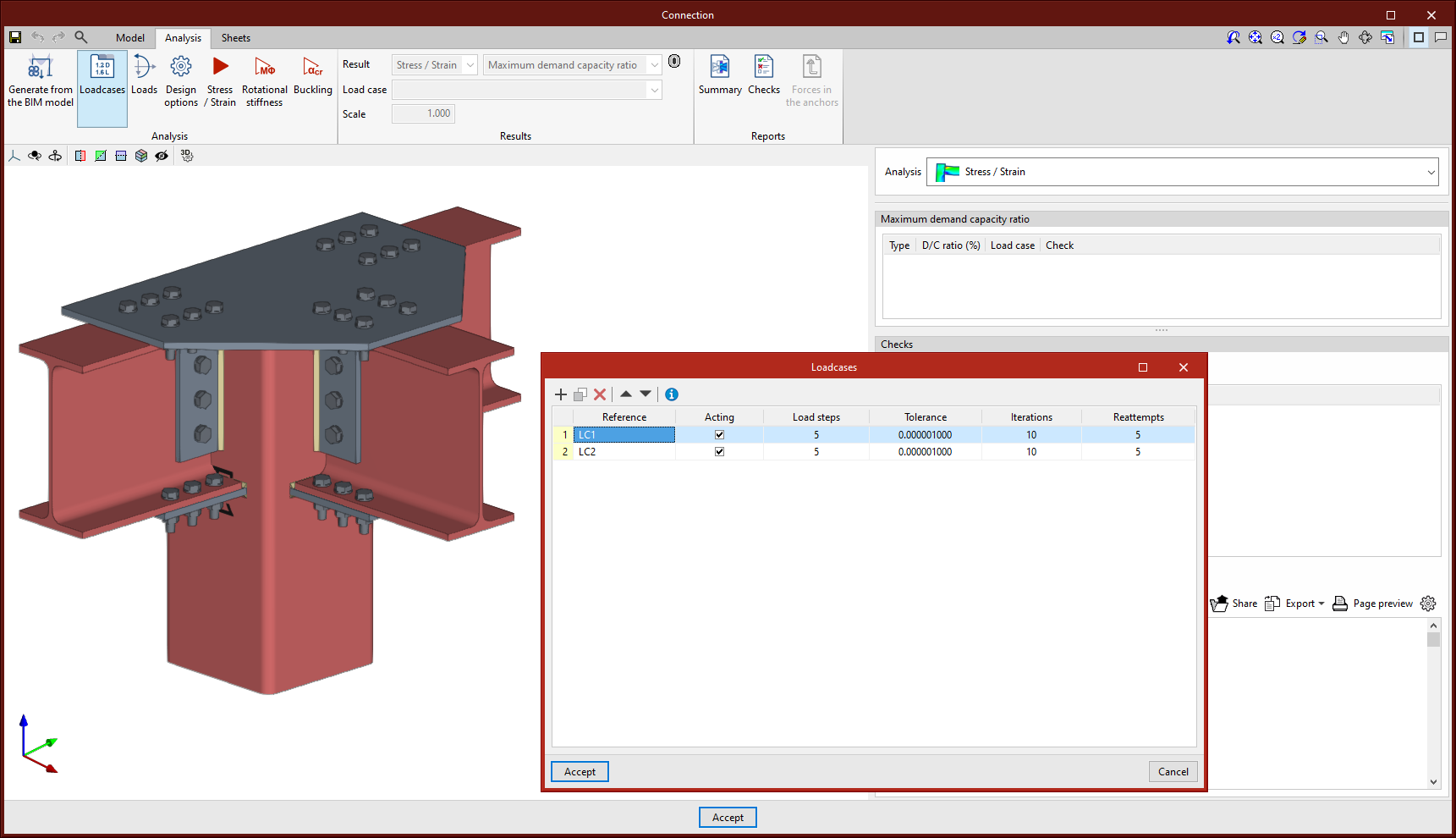
Loadcases
This option can be used for defining the load cases to be considered in the connection analysis. These load cases can be generated from the BIM model or configured manually by the user. The following parameters are defined for each load case:
- Number of load steps.
- Allowable tolerance to consider the convergence has been reached.
- Maximum number of iterations in each load step.
- Maximum number of reattempts.
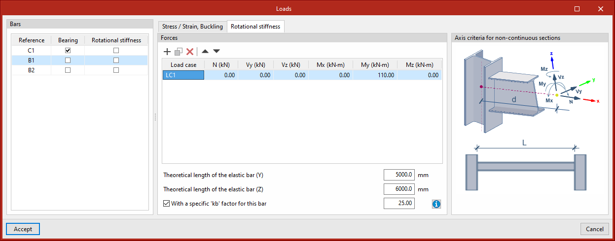
Loads
This tool opens the "Loads" dialogue box, where the loads acting on each section for each load case are defined. Tables can be copied and pasted directly from a spreadsheet. One of the sections must be the load-bearing section.
In addition to the loads, the position of the force application point can be defined for each section. This distance will also be read in the BIM model, provided that the structure has been analysed considering the finite dimension of the nodes.
Furthermore, users can also select the bars from which the rotational stiffness of the connection is to be analysed. In the central part of this window, two tabs appear to define the load tables per load case. The "Rotational stiffness" tab requires a list of loads, the lengths of the elastic bar in the structural model (used to establish the limit stiffnesses of rigid or pinned connections) and the kb factor.
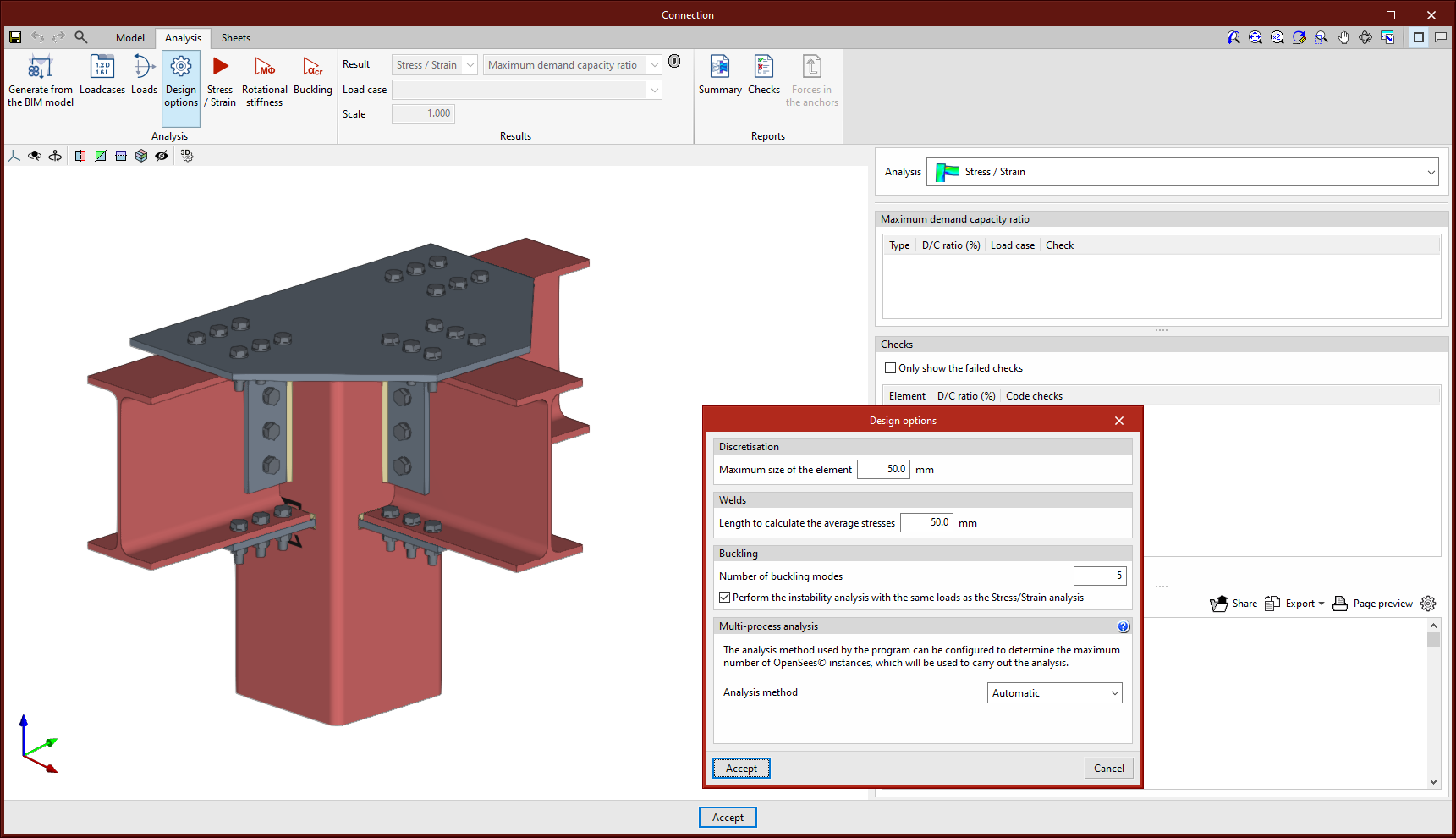
Design options
Here, users can define the following:
- The maximum discretisation size of elements.
- The length to calculate the average weld stresses.
- The multi-process analysis method of the OpenSees© analysis engine.
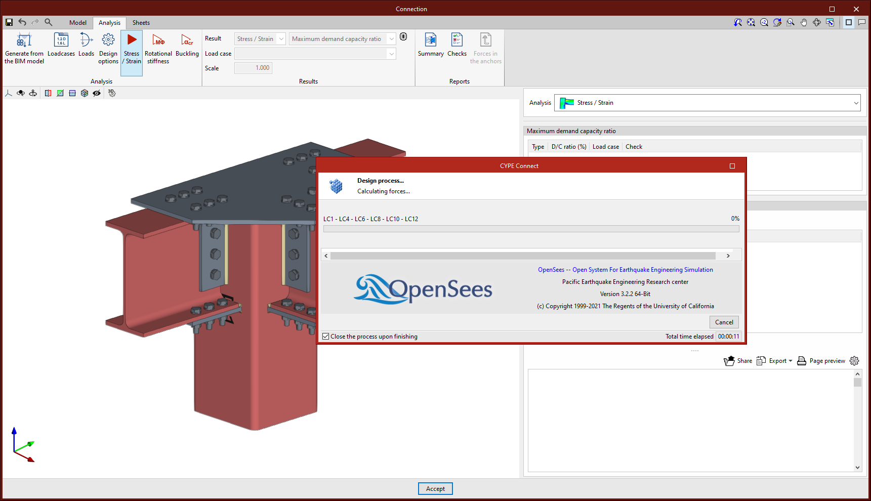
Stress / Strain
Clicking on the "Stress / Strain" button starts the stress analysis and checks. The first time the analysis is run, the implemented version of OpenSees© will be installed automatically.
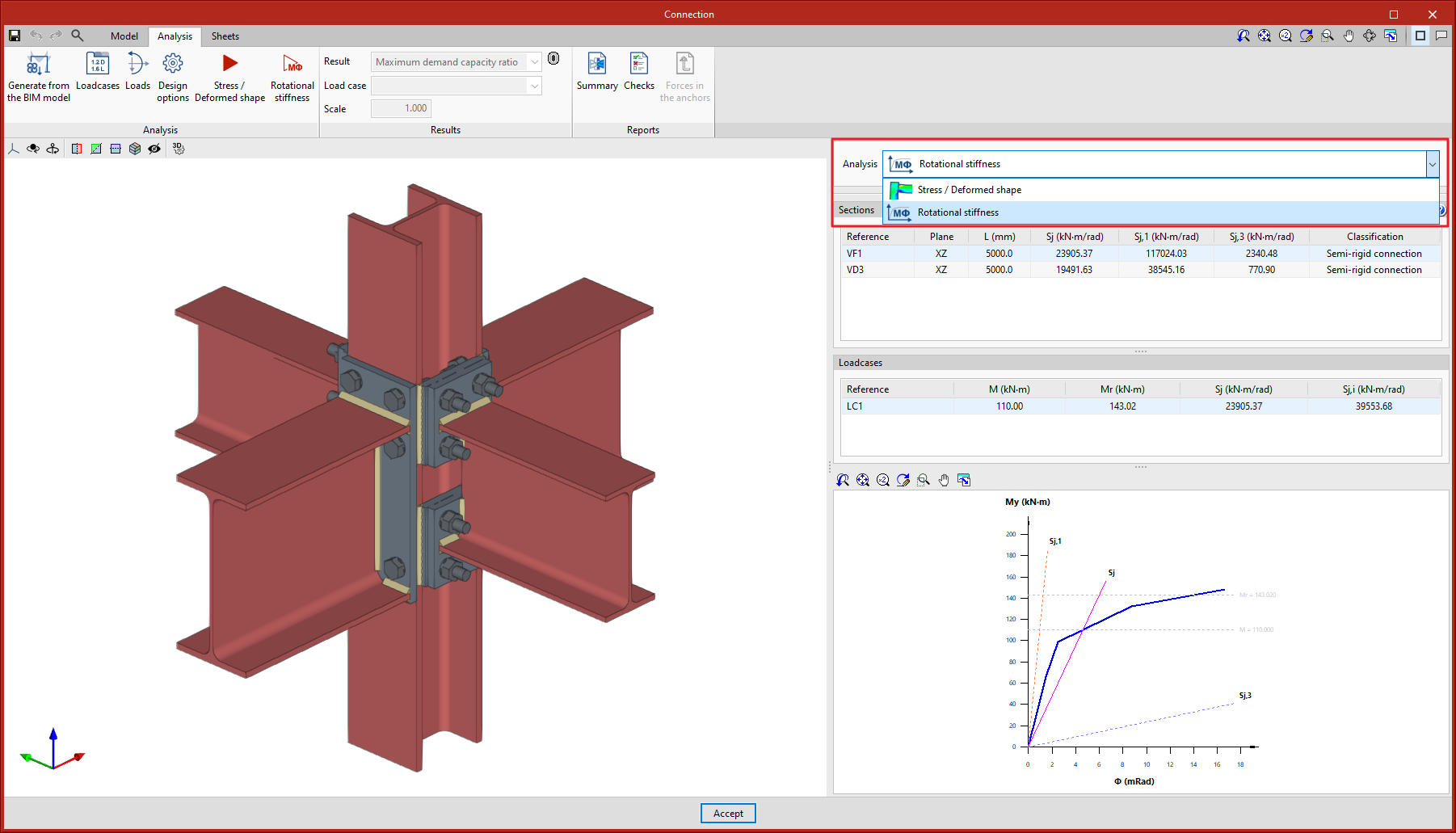
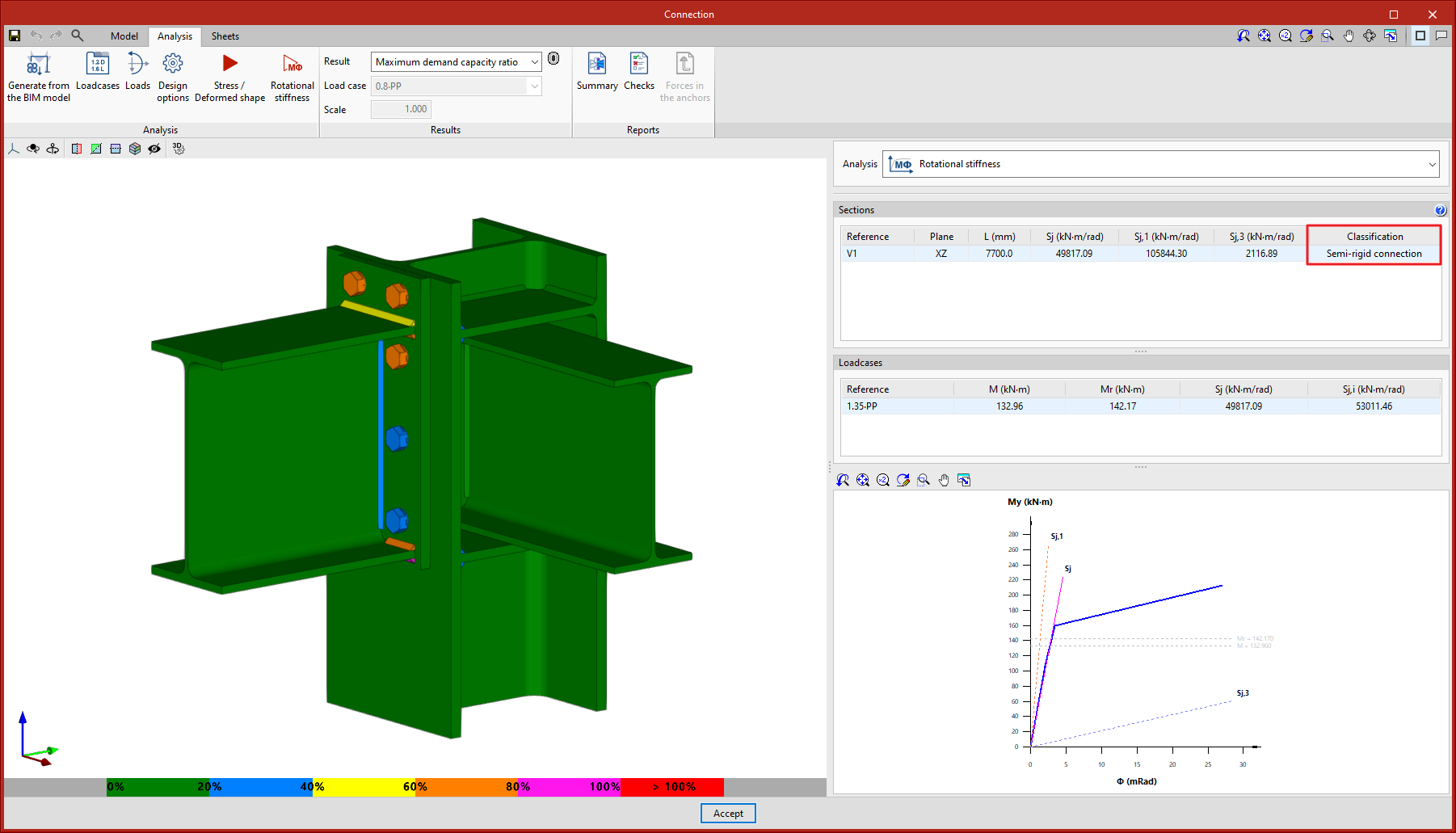
Rotational stiffness
Clicking on the "Rotational stiffness" button will start the force analysis and checks. This analysis option allows users to obtain the resistant moment, the initial stiffness, the secant stiffness and the classification of the connection (rigid, semi-rigid or pinned) of the steel sections.
The results are displayed on the right-hand side of the "Analysis" tab. In the drop-down menu at the top, you can select the type of results to be displayed, "Stress/Strain" or "Rotational stiffness". When choosing "Rotational stiffness", the program displays two tables and the "Moment - Rotation" graph.
To obtain the "Moment - Rotation" graph, the program runs an iterative process analysing the rotation in different load steps. The resistant moment is obtained when any element of the connection (plates, sections, welds or bolts) does not comply, i.e. when its demand capacity ratio is greater than 100%.
The first table shows all bars analysed with the secant stiffness and the classification of the connection in each plan. The second table displays the analysed load cases for the selected bar. Each load case indicates the acting moment, the resisting moment, the secant stiffness and the initial stiffness.
The graph shows the curves for "Moment - Rotation", "Acting moment of the selected load case", "Resistant moment", "Ultimate stiffness for rigid connections (Sj,1)" and "Ultimate stiffness for pinned connections (Sj,2)".
Classifying the connection
To classify the connection as rigid, semi-rigid or pinned, the limit stiffnesses of rigid and pinned connections must first be established. Depending on the selected steel codes, the initial stiffness or the secant stiffness will be compared with these limits.
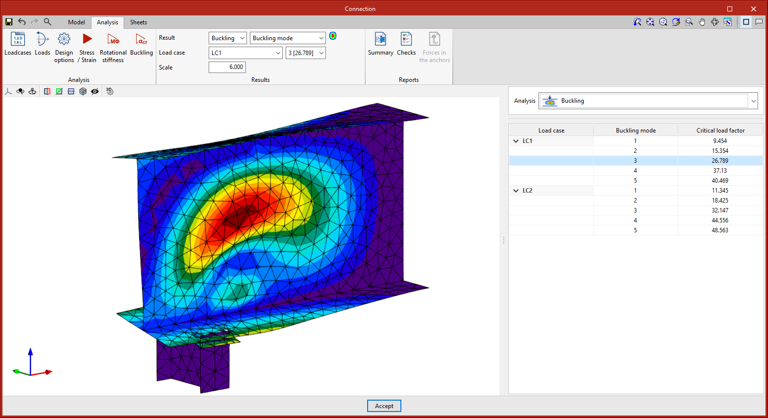
Buckling
Clicking on the "Buckling" button will start the analysis. The local buckling of a connection component occurs due to compression forces and mostly depends on the stiffness of the component and the distribution of the applied loads. The buckling analysis helps to detect unstable connection design configurations under the load of a particular load case.
There are several ways to evaluate the buckling phenomenon using Finite Elements. The one implemented in the connection analysis is the "Linear buckling analysis" which allows users to obtain the critical load factors of the different local buckling modes of the connection for a given load case.
Once the analysis is completed, we obtain the critical load factors for each of the buckling modes as well as their deformed shape. The smaller the first critical load factor, the closer we are to an unstable connection configuration.
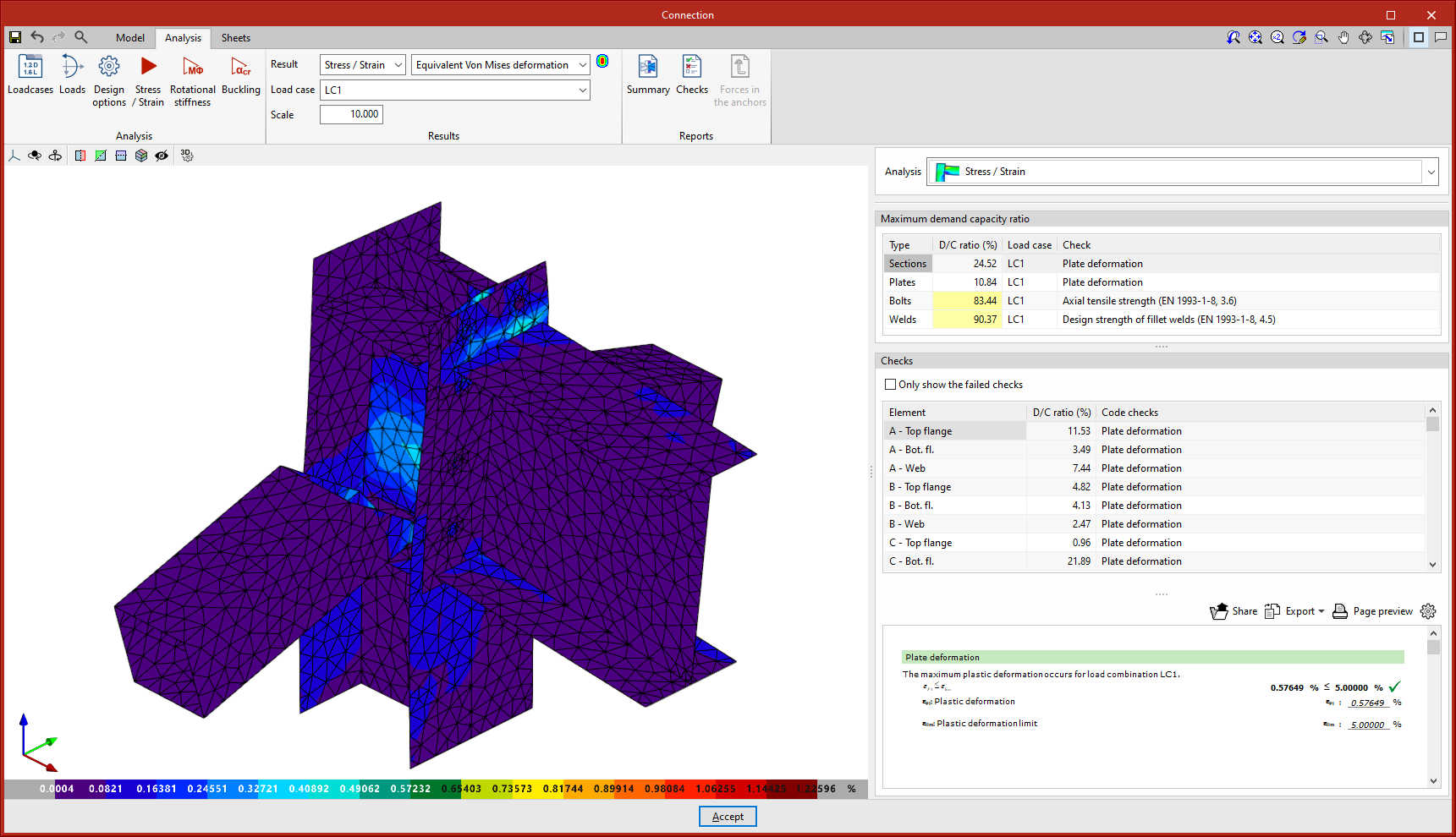
Analysis results
Maximum demand capacity ratio
When this option is selected, the elements appear in a certain colour according to their use percentage. The colour scale is displayed below the 3D view of the connection.
When clicking on an element in the connection, its checks are displayed on the right. Clicking on an empty space in the 3D view brings up all the checks.
On the right-hand side, above the “Checks” section, a table is displayed with the “Maximum demand capacity ratio” of each type of element.
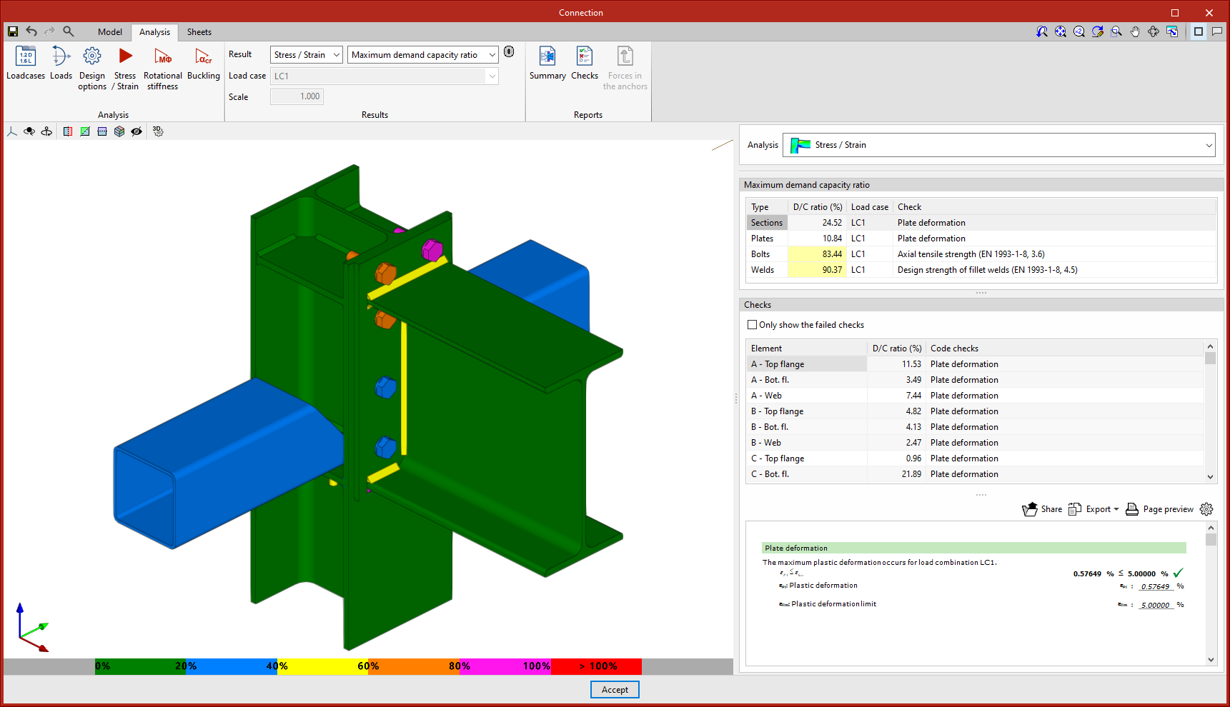
For sections and plates, the deformation is checked by setting a plastic deformation limit of 5 %. For welds, fillet weld strength is checked. For bolts, edge and bolt distance, tensile strength, shear strength and bearing resistance, as well as the interaction between shear and tension are checked. For prestressed bolts, slip resistance is also tested.
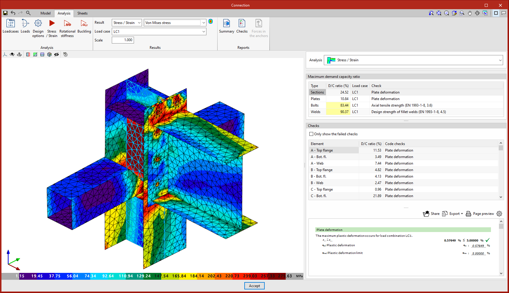
Von Mises stress
This option displays the elements with their discretisation. When clicking on any sheet, its results are displayed in a dialogue box.
Equivalent Von Mises deformation
This option represents the contour plots of the "Equivalent Von Mises deformation".
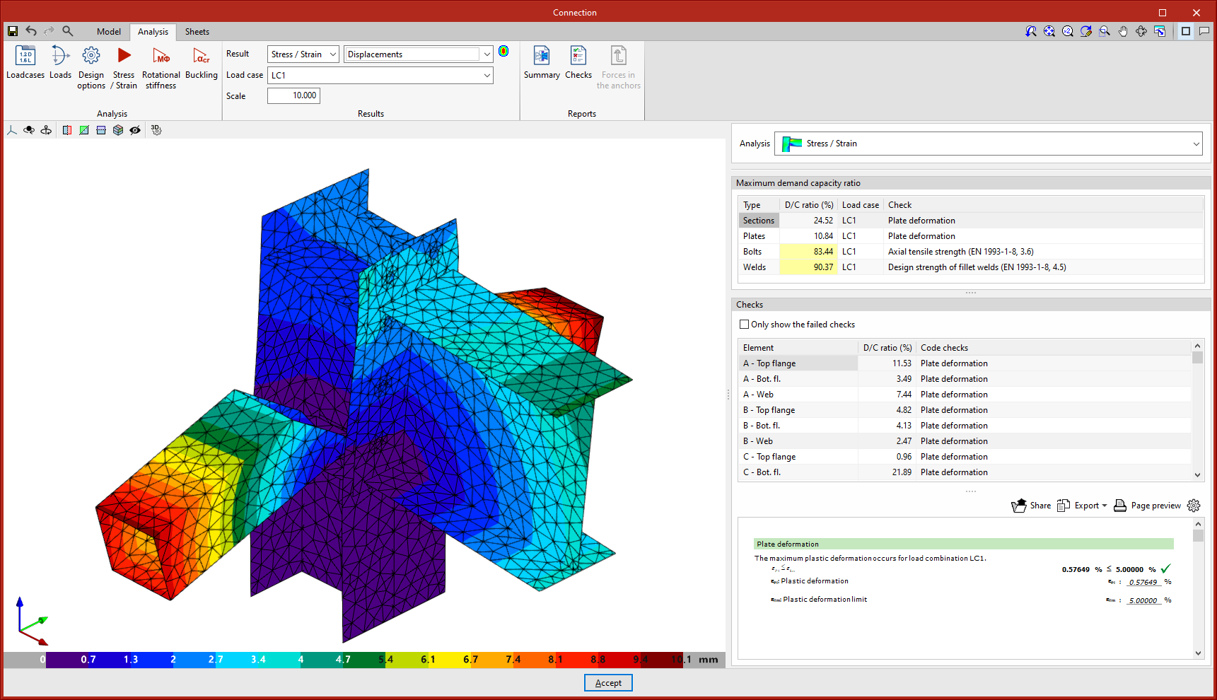
Displacements
With this option, the displacement values are displayed on the analytical model view of the connection.
Connection analysis reports
The results of analyses carried out in CYPE Connect can also be obtained as reports, which can be accessed via the "Reports" group in the top toolbar of the "Analysis" tab. The available reports include the following:
- Summarised report. This can include data on connection components, applied loads, checks and annotations.
- Checks report. This displays the points analysed according to the selected code, together with their numerical result and a warning indicating whether or not they have been verified.
- Forces in the anchors. This shows the resulting forces for each anchor and for each load combination.
Graphical information of connections
In the "Sheets" tab, there are several tools that allow detailed sheets of the connections to be obtained from the data previously entered in the modelling phase.
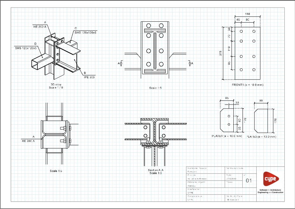
Scenes and views. To prepare the sheets, views of the connection model (elevation, floor plan, profile, 3D view, etc.) can be entered at the desired scale. The program allows both predefined views and user-created views to be entered.
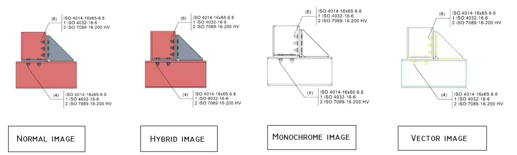
Scene drawing modes. In each scene, users can select the type of image they want to add.
- Normal image, where the elements are coloured.
- Hybrid image, where the elements are coloured and the edges are vectorised.
- Monochrome image.
- Vector image, where the elements are not filled with colour and the lines are vectorised.
Dimensions and tags. The program provides traditional drawing elements as well as dimensioning tools. Line, text or dimension styles can be manually defined and saved for use in future connection sheets.
To tag the elements, the tagging tool incorporates the most common types of tags for connection sheets. However, to speed up the process, an automatic tagging tool has been designed, which automatically generates the tag of the selected element with content and shape predefined by CYPE Connect. When dimensioning the connection elements, once the dimension has been entered, the position of the text can be modified.
Sheet composition. Once the connections have been detailed, the composition process can begin, in which it is possible to create one or more sheets with the contents of the detailing of the connections. The "Link" tool allows a reference of the content of one sheet to be inserted into another, although the "Sheet composition" option generates a mosaic with the selected sheets.
Linking with the connection model
The content of the sheets is linked to the model of the connection, i.e. the scenes and views that have been defined, as well as the element tags that have been entered, will be automatically updated if changes are made to the model of the connection. If the connection is exported to the "Connection library", the sheets will also be exported and can be reused in future projects.
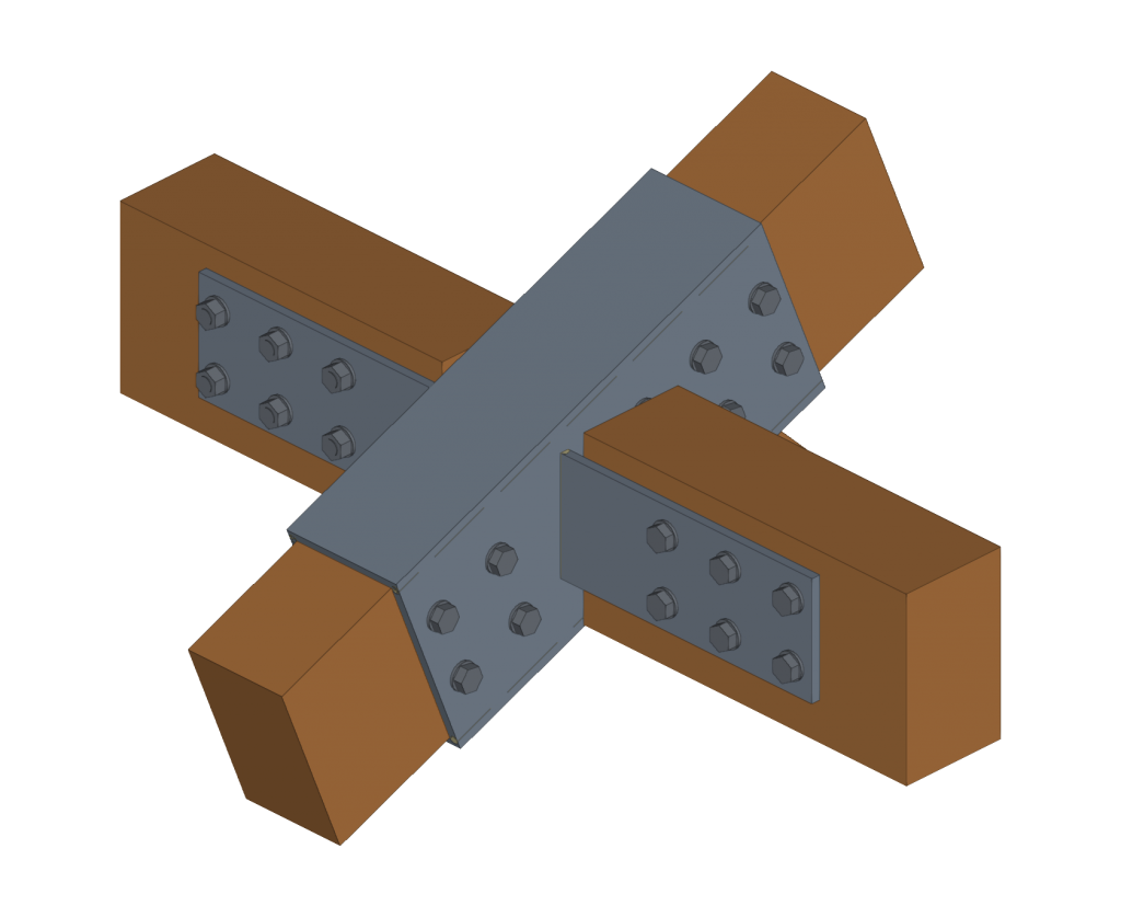
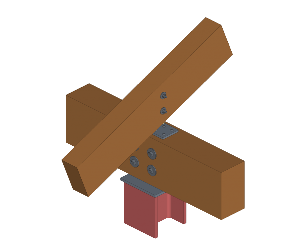
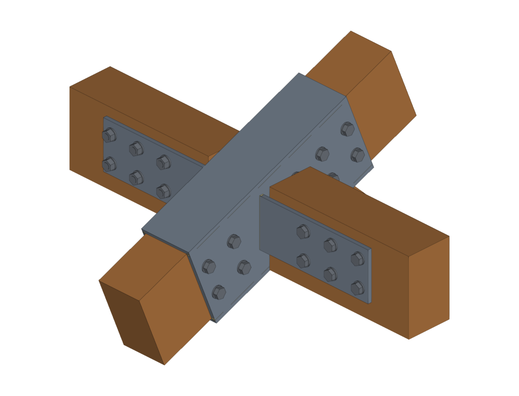
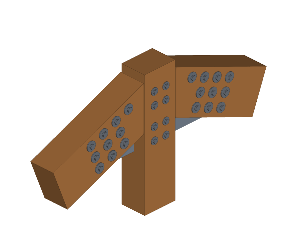
Structural timber element connections
CYPE Connect can model and analyse connections between structural timber elements and steel-to-timber elements, as well as connections between steel elements.
This feature allows users to design steel-to-timber connections. In this type of connection, forces are transmitted from one piece of timber to another by means of metal elements (fasteners and connections).
The connection between the different structural timber elements is achieved by means of dowel-type fasteners and auxiliary steel elements such as metal sheets or sections. The timber elements transmit their forces via the fasteners (bolts, dowels and screws) to all the other elements to which they are connected (steel sections and sheets).

Connections library
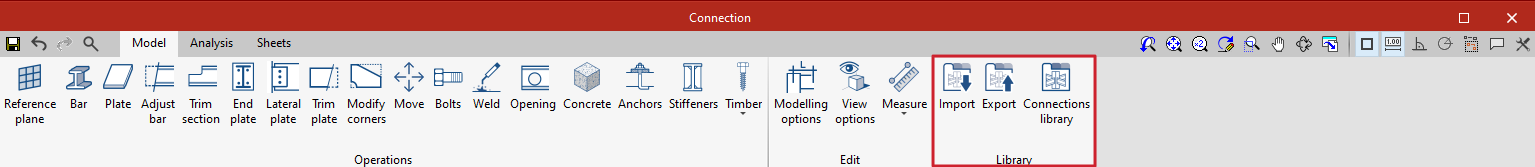
The connections library allows connections to be saved and applied to other nodes in the same job or other jobs. This library is common to CYPE Connect and StruBIM Steel. The “Import”, “Export” and “Connections library” options can be accessed from the connection editing panel.
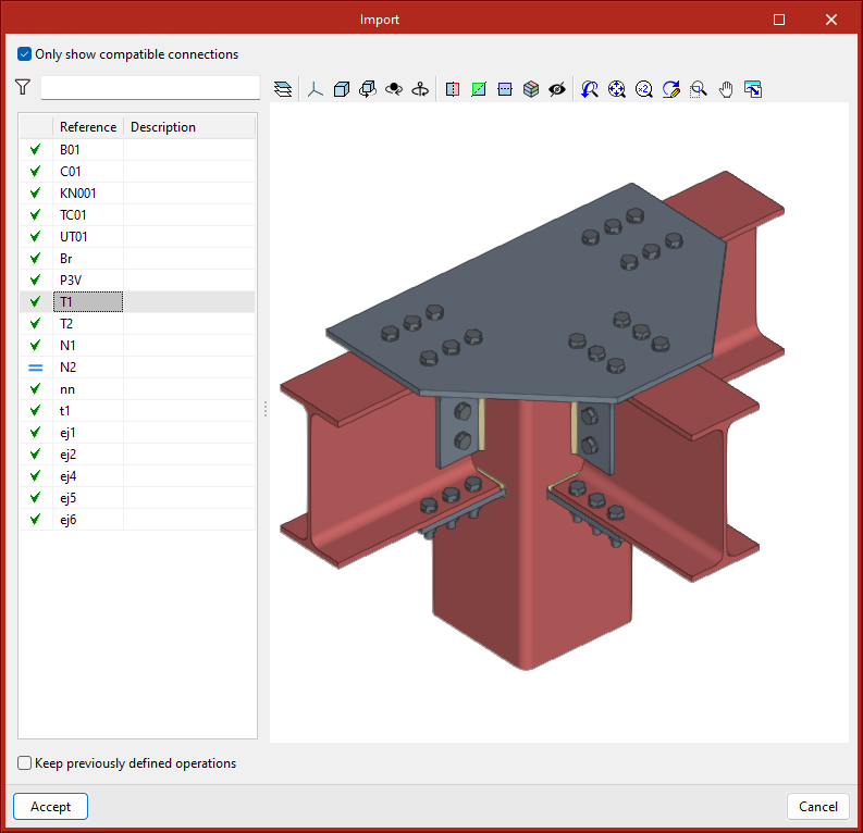
- Import
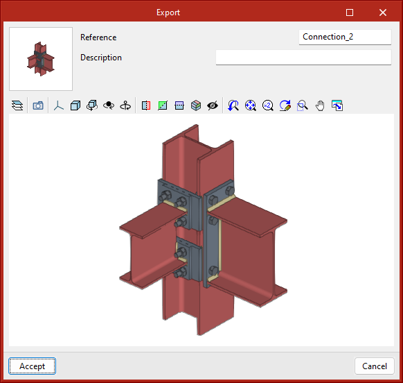
Joints between structural elements modelled in StruBIM Steel can be saved in a local library and reused in other projects. This library is compatible with CYPE Connect. - Export
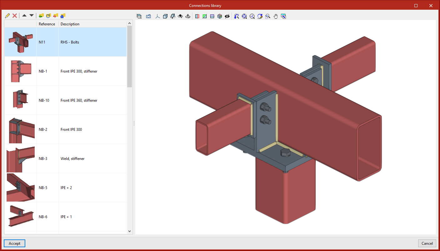
This tool allows a connection to be saved in the job's connection library with a reference, description and thumbnail image for identification. The connections exported to the connections library also save the sheets that have been defined, so that the work invested in creating the detailing sheet of the connection can be used for similar connections when applying a connection available in the library. - Connections library
The connection library includes a thumbnail view of the connection, a reference and a description. A 3D view is also displayed where the connection can be moved, shifted and orbited.
The top part shows the options related to the management of this library:
- Import elements saved on disk into the job
- Update the elements used in the project
- Export the element to a file
- Select a file with initial values for the creation of a new job
Integration into the BIMserver.center platform
Many of CYPE's programs are connected to the BIMserver.center platform and allow collaborative work to be carried out via the exchange of files in formats based on open standards.
Please note that, to work on BIMserver.center, users can register on the platform free of charge and create a profile.
When accessing a program connected to the platform, the program connects to a project in BIMserver.center. This way, the files of the projects that have been developed collaboratively in BIMserver.center are kept up to date.

Options available in CYPE Connect
The "BIMserver.center" group in the main toolbar contains the options required for using CYPE Connect together with other BIMserver.center tools.

Importing and updating BIM models
The "Update" option updates the information contained in the models previously imported from the project and also imports information from new contributions.
The import of the model is carried out according to the settings defined by the user, who can establish how new, modified and deleted elements of the BIM model are shared.

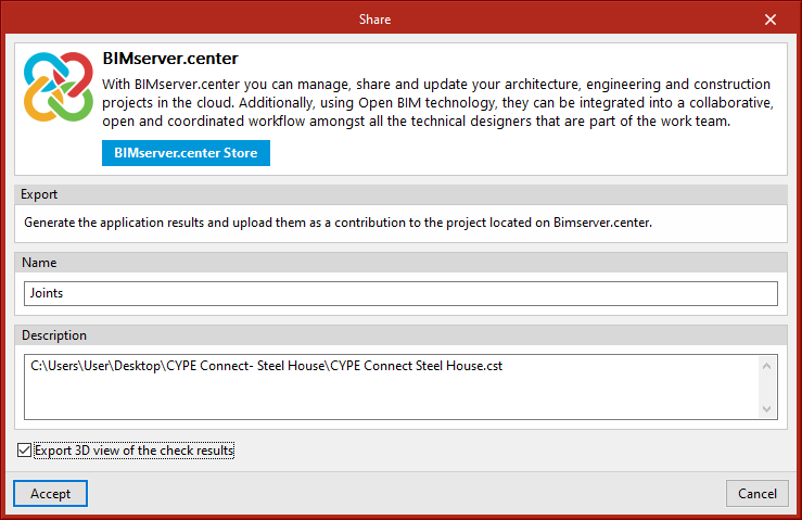
Sharing the BIM model with other users
With the "Share" button, users can export the information contained in the model developed in CYPE Connect to the BIMserver.center platform.
During the export process, a number of details can be defined regarding the identification of the files to be exported, as well as the location of the local copies that will be automatically generated.
Supported licenses and modules
CYPE Connect has different modules that can be combined to increase the tool's performance.
CCS module: CYPE Connect Steel - Steel connections
The CCS module is used for the modelling, analysis and graphical information of connections between bars in steel structures. For this to be possible, the license must include the CCS and OSP codes.
CCT module: CYPE Connect Timber - Timber connections
The CCT module is used for the modelling, analysis and graphical information of connections between bars in timber structures. As well as its own code, CCT, the licence must also include the OSP code as a prerequisite for use.
OSP module: OpenSees©. Professional version
The OpenSees analysis engine is included in CYPE Connect and is used when analysing connections between bars in steel structures. To use CYPE Connect together with StruBIM Steel, CCS and/or CCT codes are required.
SBA module: CYPE Connect Anchors - Concrete anchors
Analysing anchors using CYPE Connect can be carried out via the SBA module. This module is compatible with both StruBIM Steel and CYPE Connect and requires, in addition to its own code, the CCS and OSP codes for use.
APL module: Buckling analysis (local stability)
The "Buckling Analysis (Local Stability)" module is used to study the local stability of connections in steel structures. It is compatible with both StruBIM Steel and CYPE Connect. Both the CCS and OSP codes, as well as its own APL code, are a prerequisite for its use.